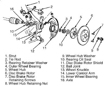
WHEEL BEARING Removal 1. Remove front hub. See HUB & KNUCKLE ASSEMBLY . Separate hub from knuckle with Knuckle Puller (T87C-1104-A) and Hub/Bearing Remover(T92C-1104-AH). 2. Remove outer bearing retainer washer. Using a press and bearing splitter, remove outer bearing cone. Remove and discard inner oil seal. Remove inner bearing cone. Remove and discard inner oil seal. Remove bearing races from knuckle. See Fig. 2 . Fig. 2: Exploded View Of Front Hub Courtesy of FORD MOTOR CO. Installation 1. Drive races into knuckle. Pack inner and outer bearing cones with grease meeting specification ESA-M1C75-B. Pack hub in area of ends of rollers. Install inner cone into knuckle bore so that it rests in level position. Lubricate lip of NEW inner oil seal. Form grease into a strip, concentrated along edges of inner oil seal lip. Tap inner oil seal into place. 2. Install original outer bearing spacer, or spacer selected from bearing preload procedure, into knuckle bore. Lubricate lip of NEW inner oil seal. Form grease into a strip, concentrated along edges of inner oil seal lip. Tap outer oil seal into place. 3) Install knuckle and hub. See HUB & KNUCKLE ASSEMBLY . Using spacer from Spacer Selector (T87C-1104-B), position hub/rotor assembly into knuckle bore, then press into position. NOTE: The outer bearing retainer is preselected to provide correct bearing preload. Save it for use during reassembly.
HUB & KNUCKLE ASSEMBLY Removal 1. Raise and support vehicle. Remove wheel. Apply brakes to prevent hub from rotating. Remove and discard drive axle lock nut. 2. Remove clip which secures brake hose to strut bracket. Separate tie rod end from steering knuckle. Remove brake caliper and wire aside. Do not allow caliper to hang by brake hose. 3. Remove clamp bolt and nut where lower control arm ball joint connects to steering knuckle. 4. Pry lower control arm downward. Separate ball joint from steering knuckle. Remove bolts attaching steering knuckle between flanges of strut bracket. Slide hub/knuckle assembly from end of drive axle. If binding occurs or hub is frozen to drive axle, use a hub puller to press axle from hub. Installation 1. Apply a thin coat of SAE 30 oil to drive axle splines. Slide hub/knuckle assembly onto drive axle. Stop at area where uppermost arm of steering knuckle seats into strut bracket. Install and tighten strut bracket nuts and bolts to 69-86 ft. lbs. (93-117 N.m). 2. To complete installation, reverse removal procedure. Tighten ball joint pinch bolt to 32-40 ft. lbs. (43-54 N.m). Tighten caliper bolts to 29-36 ft. lbs. (39-49 N.m). Install and tighten NEW drive axle lock nut to 116-174 ft. lbs. (157-235 N.m). Stake NEW axle lock nut into shaft groove. Tighten tie rod nut to 22-33 ft. lbs. (29-44 N.m). Install NEW cotter pin. NOTE: Always use a NEW drive axle lock nut when servicing hub or drive axle. CAUTION: If lock nut flange cracks, even slightly, during staking process, it must be replaced.
Jul 7, 2009 at 11:24 AM