Good afternoon,
You will need to replace the module, seat belt pretensioners, and the crash sensors.
Then the dealer will have to program the module for you.
Roy
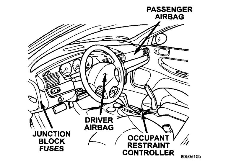
OCCUPANT RESTRAINT CONTROLLER
REMOVAL
1. Disconnect and isolate the battery negative remote cable. Wait two minutes for the capacitor to discharge.
2. For a manual transmission, remove shifter knob and boot.
3. For automatic transmission models, remove shifter knob and unsnap shift indicator bezel.
4. Remove the four attaching screws to floor console.
5. Remove parking brake lever. Refer to Brakes, Parking Brake, Parking Brake Lever, Removal.
6. Remove three mounting nuts to ORC.
7. Disconnect wire harness connectors and remove ORC from mounting studs.
INSTALLATION
CAUTION: Use supplied nuts only.
1. With the battery disconnected, position the ORC (arrow pointing forward) on center tunnel area mounting studs.
2. Connect wire harness connector.
3. Attach the three mounting nuts and tighten to 10 to 14 Nm (85 to 125 in. Lbs.) Torque.
4. Install the parking brake lever. Refer to Brakes, Parking Brake, Parking Brake Lever, Installation.
5. Install the floor console.
6. Install the four attaching screws to floor console.
7. For automatic transmission models, install the shift indicator bezel and shifter knob.
8. For a manual transmission, install the shifter boot and knob.
WARNING: DO NOT CONNECT THE BATTERY NEGATIVE CABLE REMOTE TERMINAL. REFER TO ELECTRICAL, RESTRAINTS, DIAGNOSIS AND TESTING - AIRBAG SYSTEM FIRST.
More information on the system
AIRBAG SYSTEM/OCCUPANT RESTRAINT CONTROLLER SYSTEM
The 2002 Airbag System contain the following components: Occupant Restraint Controller (ORC), Airbag Warning Indicator, Clockspring, Driver and Passenger Dual Squib Airbags, Seat belt Tensioners, Left and Right Side Impact Airbag Control Module (SIACM), and Curtain (roof mounted) Air-bags.
The (ORC)is a new type of Airbag Control Module (ACM) that supports staged airbag deployment. Staged deployment is the ability to trigger airbag system squib inflators all at once or individually as needed to provide the appropriate restraint for the severity of the impact. The ACM has four major functions: PCI Bus communications, on-board diagnostics, impact sensing, and component deployment. The ACM also contains an energy-storage capacitor. This capacitor stores enough electrical energy to deploy the front airbag components for two seconds following a battery disconnect or failure during an impact. The ACM is secured to the floor panel transmission tunnel between the front seats inside the vehicle. The ACM cannot be repaired or adjusted and must be replaced.
The ACM sends and/or receives PCI Bus messages with the Instrument Cluster (MIC), Body Control Module (BCM), Left and Right Side Impact Airbag Control Module (SIACM) and Powertrain Control Module (PCM). Diagnostic trouble codes will be set if the communication with these modules is lost or contains invalid information.
The microprocessor in the ACM monitors the impact sensor signal and the airbag system electrical circuits to determine the system readiness. The ACM also monitors bus messages from both SIACM. If the ACM detects a monitored system fault or SIACM fault, it sends a message to the instrument cluster via PCI bus to turn on the airbag warning indicator. The ACM can set both active and stored diagnostic trouble codes to aid in the diagnosing system problems. See DIAGNOSTIC TROUBLE CODES.
The ACM has an internal accelerometer that senses the rate of vehicle deceleration, which provides verification of the direction and severity of an impact. A pre-programmed decision algorithm in the ACM microprocessor determines when the deceleration rate is severe enough to require airbag system protection. The ACM also uses the crash severity to determine the level of driver and front passenger deployment, low medium or high. When the programmed conditions are met, the ACM sends an electrical signal to deploy the appropriate airbag system components.
The airbag system is a sensitive, complex electromechanical unit. Before attempting to diagnose or service any airbag system or related steering wheel, steering column, or instrument panel components you must first disconnect and isolate the battery negative (ground) cable. Wait two minutes for the system capacitor to discharge before further system service. This is the only sure way to disable the airbag system. Failure to do this could result in accidental airbag deployment and possible personal injury. Never strike or kick the airbag control module, as it can damage the impact sensor or affect its calibration. If an airbag control module is accidentally dropped during service, the module must be scrapped and replaced with a new unit.
The airbag warning lamp is the only point at which the customer can observe symptoms of a system malfunction. Whenever the ignition key is turned to the run or start position, the MCI performs a lamp check by turning the airbag warning indicator on for 6-8 seconds. After the lamp check, if the indicator turns on, it means that the ACM has checked the system and found it to be free of discernible malfunctions. If the lamp remains on, there could be an active fault in the system or the MIC lamp circuit may be internally shorted to ground. If the lamp comes on and stays on for a period longer than 6-8 seconds, then goes off, there is usually an intermittent problem in the system.
DRIVER AIRBAG
The airbag protective trim cover is the most visible part of the driver side airbag system. The protective trim cover is fitted to the front of the airbag module and forms a decorative cover in the center of the steering wheel. The module is mounted directly to the steering wheel. Located under the trim cover are the horn switch, the airbag cushion, and the airbag cushion supporting components. The airbag module includes a housing to which the cushion and hybrid inflator are attached and sealed. For 2002 driver airbag has dual stage squib inflators that include a small canister of highly compressed argon gas. The ACM uses vehicle crash severity, to determine the level of airbag deployment. When supplied with the proper electrical signal, the hybrid inflator or inflators discharge the compressed gas it contains directly into the cushion. The airbag module cannot be repaired, and must be replaced if deployed or in any way damaged.
WARNING: THE DRIVER AIRBAG MODULE CONTAINS ARGON GAS PRESSURIZED TO OVER 17236.89 KPA (2500 PSI). DO NOT ATTEMPT TO DISMANTLE AN AIRBAG MODULE OR TAMPER WITH ITS INFLATOR. DO NOT PUNCTURE, INCINERATE, OR BRING INTO CONTACT WITH ELECTRICITY. DO NOT STORE AT TEMPERATURE EXCEEDING 93° C (200° F). REPLACE AIRBAG SYSTEM COMPONENTS ONLY WITH PARTS SPECIFIED IN THE CHRYSLER MOPAR PARTS CATALOG. SUBSTITUTE PARTS MAY APPEAR INTERCHANGEABLE, BUT INTERNAL DIFFERENCES MAY RESULT IN INFERIOR OCCUPANT PROTECTION. THE FASTENERS, SCREWS, AND BOLTS ORIGINALLY USED FOR THE AIRBAG SYSTEM COMPONENTS HAVE SPECIAL COATINGS AND ARE SPECIFICALLY DESIGNED FOR THE AIRBAG SYSTEM. THEY MUST NEVER BE REPLACED WITH ANY SUBSTITUTES. ANY TIME A NEW FASTENER IS NEEDED, REPLACE IT WITH THE CORRECT FASTENERS PROVIDED IN THE SERVICE PACKAGE OR SPECIFIED IN THE MOPAR PARTS CATALOG.
CAUTION: Deployed front airbags may or may not have live pyrotechnic material within the airbag inflator. Do not dispose of 2002 model year driver and passenger airbags unless you are sure of complete deployment. Please refer to the hazardous substance control system for proper disposal. Dispose of deployed airbags in a manner consistent with state, provincial, local, and federal regulations. Use the table to identify the status of the airbag squib.
AIRBAG SQUIB STATUS
1. Using a DRBIII(R) read Airbag DTC's.
ImageOpen In New TabZoom/Print
If the active codes are present.
ImageOpen In New TabZoom/Print
If neither of the following codes is an active code.
CLOCKSPRING
The clockspring is mounted on the steering column behind the steering wheel. This assembly consist of a plastic housing which contains a flat, ribbon-like, electrically conductive tape that winds and unwinds with the steering wheel rotation. The clockspring is used to maintain a continuous electrical circuit between the instrument panel wiring the driver airbag, the horn, and the vehicle speed control switches if equipped. The clockspring must be properly centered when it is reinstalled on the steering column following any service procedure, or if could be damaged. The clockspring cannot be repaired and it must be replaced.
PASSENGER AIRBAG
The airbag door in the instrument panel top cover above the glove box is the most visible part of the passenger side airbag system. The airbag door has a living hinge at the top, which is secured to the instrument panel top cover. Located under the airbag door is the airbag cushion and it's supporting components. The airbag module includes a housing to which the cushion and hybrid inflators are attached and sealed. For 2002 the front passenger airbag is equipped with dual stage squib inflators that include a small canister of highly compressed argon gas. The ACM uses vehicle crash severity, to determine the level of airbag deployment. When supplied with the proper electrical signal, the hybrid inflator or inflators discharge the compressed gas if contains directly into the airbag. The airbag module cannot be repaired, and must be replaced if deployed or in any way damaged.
WARNING: THE PASSENGER AIRBAG MODULE CONTAINS ARGON GAS PRESSURIZED TO 17236.89 KPA (2500 PSI). DO NOT ATTEMPT TO DISMANTLE AN AIRBAG MODULE OR TAMPER WITH ITS INFLATOR. DO NOT PUNCTURE, INCINERATE, OR BRING INTO CONTACT WITH ELECTRICITY. DO NOT STORE AT TEMPERATURE EXCEEDING 93° C(200° F). REPLACE AIRBAG SYSTEM COMPONENTS ONLY WITH PARTS SPECIFIED IN THE MOPAR PARTS CATALOG. SUBSTITUTE PARTS MAY APPEAR INTER-CHANGEABLE, BUT INTERNAL DIFFERENCES MAY RESULT IN INFERIOR OCCUPANT PROTECTION. THE FASTENERS, SCREWS, AND BOLTS ORIGINALLY USED FOR THE AIRBAG SYSTEM COMPONENTS HAVE SPECIAL COATINGS AND ARE SPECIFICALLY DESIGNED FOR THE AIRBAG SYSTEM. THEY MUST NEVER BE REPLACED WITH ANY SUBSTITUTES. ANY TIME A NEW FASTENER IS NEEDED, REPLACE IT WITH THE CORRECT FASTENERS PROVIDED IN THE SERVICE PACKAGE OR SPECIFIED IN THE MOPAR PARTS CATALOG.
CAUTION: Deployed front airbags may or may not have live pyrotechnic material within the airbag inflator. Do not dispose of 2002 model year driver and passenger airbags unless you are sure of complete deployment. Please refer to the hazardous substance control system for proper disposal. Dispose of deployed airbags in a manner consistent with state, provincial, local, and federal regulations. Use the following table to identify the status of the airbag squib.
AIRBAG SQUIB STATUS
1. Using a DRBIII(R) read Airbag DTC's
imageOpen In New TabZoom/Print
If the active codes are present.
ImageOpen In New TabZoom/Print
If neither of the codes is an active code.
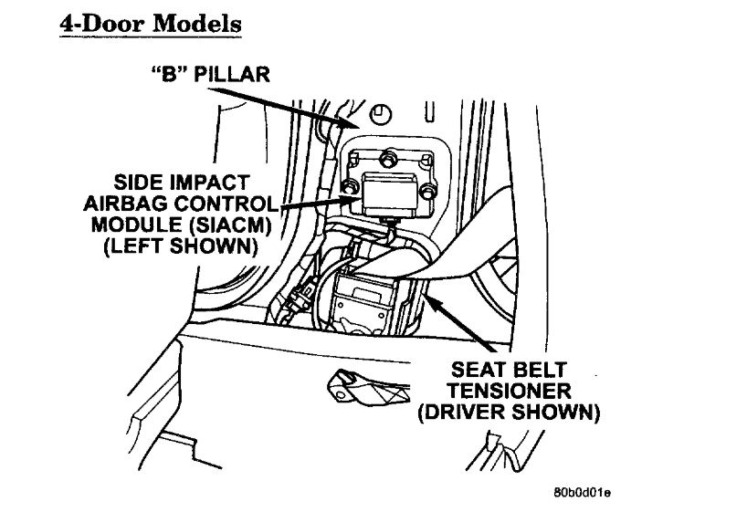
SEAT BELT TENSIONER (SBT)
The JR41 4-door driver and front passenger seat belt (retractor) tensioners are mounted to the inboard side of the "B" pillar at the floor. The tensioner is an integral part of the seat belt retractor. At the onset of an impact event the ACM uses the seat belt tensioner to rapidly retracts the seat belt. With the slack removed, the occupant's forward motion in an impact will be reduced as will the likelihood of contacting interior components. The seat belt tensioner cannot be repaired, if damaged or defective it must be replaced. The ACM continuously monitors the resistance of the seat belt tensioner circuits an open or shorted conditions.
The JR27 convertible driver and front passenger seat belt (buckle) tensioners are mounted to the inboard side of the front seats. The seat belt buckle is connected directly to the seat belt tensioner cable. At the onset of an impact event the ACM uses the seat belt tensioner to rapidly retract the seat belt buckles. With the slack removed, the occupant's forward motion in an impact will be reduced as will the likelihood of contacting interior components. The seat belt tensioner cannot be repaired, if damaged or defective it must be replaced. The ACM continuously monitors the resistance of the seat belt tensioner circuits an open or shorted conditions.
SIDE IMPACT AIRBAG CONTROL MODULE (SIACM)
Supplemental driver and passenger curtain airbags provide side impact protection for the occupants. Each side airbag has it's own side impact airbag control module (SIACM)to provide independent impact sensing and deployment. SIACM are located on the left and right B post just above the seat belt retractor. One, same part number, SIACM is used on both side of the vehicle. However, for proper PCI bus operation each SIACM must have a unique module identification. To provide the unique module identification for both, left and right, the SIACM software looks for a ground on cavity #5 of the SIACM connector. If cavity #5 is grounded the SIACM communicates as a left SIACM otherwise it communicates as a right SIACM. The SIACM performs self diagnostics and circuit tests to determine if the system is functioning properly. If the test finds a problem the SIACM will set both active and stored diagnostic trouble codes. If a DTC is active the SIACM will request that the airbag warning lamp be turned on. The results of the system test are transmitted on the PCI Bus to the ACM once each second or on change in lamp state. If the warning lamp status message from the either SIACM contains a lamp on request, the ACM will set an active DTC. At the same time as the DTC is set, the ACM sends a PCI Bus message to the (MIC) requesting the airbag warning indicator be turned on. Observe all ACM warning and caution statements when servicing or handling the SIACM. SIACM are not repairable and must be replaced if they are dropped.
WARNING: THE AIRBAG SYSTEM IS A SENSITIVE, COMPLEX ELECTROMECHANICAL UNIT. BEFORE ATTEMPTING TO DIAGNOSE OR SERVICE ANY AIRBAG SYSTEM OR RELATED STEERING WHEEL, STEERING COLUMN, OR INSTRUMENT PANEL COMPONENTS YOU MUST FIRST DISCONNECT AND ISOLATE THE BATTERY NEGATIVE (GROUND) CABLE. WAIT TWO MINUTES FOR THE SYSTEM CAPACITOR TO DISCHARGE BEFORE FURTHER SYSTEM SERVICE. THIS IS THE ONLY SURE WAY TO DISABLE THE AIRBAG SYSTEM. FAILURE TO DO THIS COULD RESULT IN ACCIDENTAL AIRBAG DEPLOYMENT AND POSSIBLE PERSONAL INJURY. NEVER STRIKE OR KICK THE AIRBAG CONTROL MODULE, AS IT CAN DAMAGE THE IMPACT SENSOR OR AFFECT ITS CALIBRATION. IF AN AIRBAG CONTROL MODULE IS ACCIDENTALLY DROPPED DURING SERVICE, THE MODULE MUST BE SCRAPPED AND REPLACED WITH A NEW UNIT.
The airbag warning lamp is the only point at which the customer can observe symptoms of a system malfunction. Whenever the ignition key is turned to the run or start position, the MIC performs a lamp check by turning the airbag warning indicator on for 6-8 seconds. After the lamp check, if the indicator turns on, it means that the ACM has checked the system and found it to be free of discernible malfunctions. If the lamp remains on, there could be an active fault in the system or the MIC lamp circuit may be internally shorted to ground. If the lamp comes on and stays on for a period longer than 6-8 seconds then goes off, there is usually an intermittent problem in the system.
CURTAIN AIRBAGS
The Left and Right curtain airbag modules are located in the outboard edge of the roof under the headliner, just above the door opening. The curtain airbag contains a squib and inflator (a small canister of highly compressed argon gas) and a mounting bracket mounted to the C post and tethered to the A post. When supplied with the proper. Electrical signal the inflator can discharge the compress gas it contains directly into the curtain airbag. Upon deployment, the curtain will tear open the headliner allowing the curtain airbag to fully deploy between the headliner and seat. The curtain airbag module cannot be repaired and must be replaced if deployed or in any way damaged.
WARNING: THE PASSENGER AIRBAG MODULE CONTAINS ARGON GAS PRESSURIZED TO 17236.89 KPA (2500 PSI). DO NOT ATTEMPT TO DISMANTLE AN AIRBAG MODULE OR TAMPER WITH ITS INFLATOR. DO NOT PUNCTURE, INCINERATE, OR BRING INTO CONTACT WITH ELECTRICITY. DO NOT STORE AT TEMPERATURE EXCEEDING 93° C(200° F). REPLACE AIRBAG SYSTEM COMPONENTS ONLY WITH PARTS SPECIFIED IN THE MOPAR PARTS CATALOG. SUBSTITUTE PARTS MAY APPEAR INTERCHANGEABLE, BUT INTERNAL DIFFERENCES MAY RESULT IN INFERIOR OCCUPANT PROTECTION. THE FASTENERS, SCREWS, AND BOLTS ORIGINALLY USED FOR THE AIRBAG SYSTEM COMPONENTS HAVE SPECIAL COATINGS AND ARE SPECIFICALLY DESIGNED FOR THE AIRBAG SYSTEM. THEY MUST NEVER BE REPLACED WITH ANY SUBSTITUTES. ANY TIME A NEW FASTENER IS NEEDED, REPLACE IT WITH THE CORRECT FASTENERS PROVIDED IN THE SERVICE PACKAGE OR SPECIFIED IN THE MOPAR PARTS CATALOG.
SPECIAL TOOLS
Some airbag diagnostic test use special tools, 8310 and 8443 airbag load tool, for testing squib circuits. The load tools contain fixed resistive loads, jumpers and adapters. The fixed loads are connected to cables and mounted in a storage case. The cables can be directly connected to some airbag system connectors. Jumpers are used to convert the load tool cable connectors to the other airbag system connectors. The adapters are connected to the module harness connector to open shorting clips and protect the connector terminal during testing. When using the load tool follow all of the safety procedures in the service information for disconnecting airbag system components. Inspect the wiring, connector and terminals for damage or misalignment. Substitute the airbag load tool in place of a Driver or Passenger Airbag, curtain airbag, clockspring, or seat belt tensioner (use a jumper if needed). Then follow all of the safety procedures in the service information for connecting airbag system components. Read the module active DTC's. If the module reports NO ACTIVE DTC's the defective component has been removed from the system and should be replaced. If the DTC is still active, continue this process until all components in the circuit have been tested. Then disconnect the module connector and connect the matching adapter to the module connector. With all airbags disconnected and the adapter installed the squib wiring can be tested for open and shorted conditions.
DIAGNOSTIC TROUBLE CODES
Airbag diagnostic trouble codes consist of active and stored codes. If more than one code exists, diagnostic priority should be given to the active codes. Each diagnostic trouble code is diagnosed by following a specific testing procedure. The diagnostic test procedures contain step-by-step instructions for determining the cause of the trouble codes. It is not necessary to perform all of the tests in this book to diagnose an individual code.
Always begin by reading the diagnostic trouble codes using the DRBIII(R). Then begin diagnostic with the Table of Contents. This will direct you to the specific test(s) that must be performed. Active diagnostic trouble codes for the airbag system are not permanent and will change the moment the reason for the code is corrected. In certain test procedures within this manual, diagnostic trouble codes are used as a diagnostic tool.
ACTIVE CODES
The code becomes active as soon as the malfunction is detected or key-in, whichever occurs first. An active trouble code indicates an on-going malfunction. This means that the defect is currently there every time the airbag control module checks that circuit or component. It is impossible to erase an active code. Active codes automatically erase by themselves when the reason for the code has been corrected. With the exception of the warning lamp trouble codes or malfunctions, when a malfunction is detected, the airbag lamp remains lit for a minimum of 12 seconds or as long as the malfunction is present.
STORED CODES
Airbag codes are automatically stored in the ORC's memory as soon as the malfunction is detected. The exception is the Loss of Ignition Run Only code which is an active code only. A stored code indicates there was an active code present at some time. However, the code currently may not be present as an active code, although another code could be active. When a trouble code occurs, the airbag warning indicator illuminates for 12 seconds minimum (even if the problem existed for less than 12 seconds). The code is stored, along with the time in minutes it was active, and the number of times the ignition has been cycled since the problem was last detected. The minimum time shown for any code will be one minute, even if the code was actually present for less than one minute. Thus, the time shown for a code that was present for two minutes 13 seconds, for example, would be three minutes. If a malfunction is detected a diagnostic trouble code is stored and will remain stored. When and if the malfunction ceases to exist, an ignition cycle count will be initiated for that code. If the ignition cycle count reaches 100 without a reoccurrence of the same malfunction, the diagnostic trouble code is erased and that ignition cycle counter is reset to zero. If the malfunction reoccurs before the count reaches 100, then the ignition cycle counter will be reset and the diagnostic trouble code will continue to be a stored code. If a malfunction is not active while performing a diagnostic test procedure, the active code diagnostic test will not locate the source of the problem. In this case, the stored code can indicate an area to inspect. It no obvious problems are found, erase stored codes, and with the ignition on wiggle the wire harness and connectors, rotate the steering wheel from stop to stop. Recheck for codes periodically as you work through the system. This procedure may uncover a malfunction that is difficult to locate.
Images (Click to make bigger)
Sunday, April 21st, 2019 AT 10:52 AM