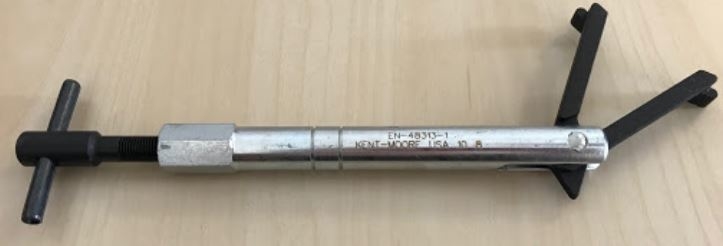
The most likely culprit would be a bad camshaft actuator assembly item . Being a 2008 and a 3.6 have the timing chains and tensioners been replaced yet? If not they are very likely worn and due for replacement. However if the only issue is the actuator it can be replaced on it's own. You need a special tool EN-48313 to hold the timing chain in position so the actuator can be removed. Without it you would need to remove the entire front cover and remove the timing chain. Then put it all back into time after replacing the actuator.
Remove the lower intake manifold. Remove the right camshaft cover.
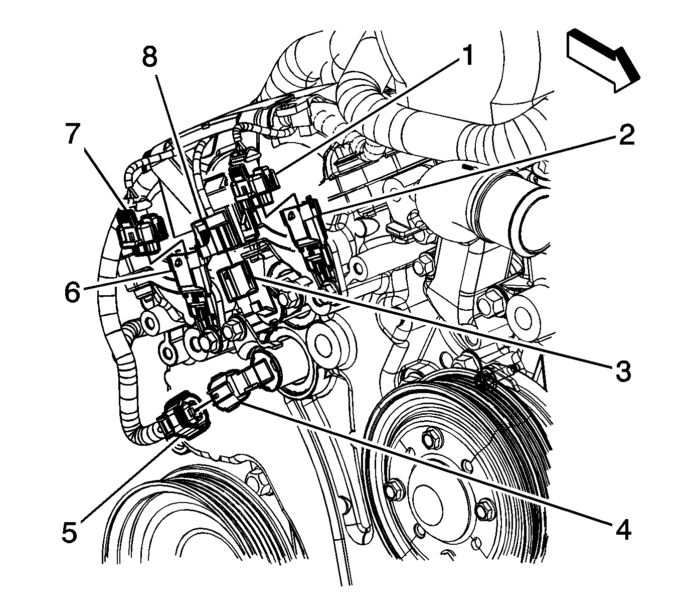
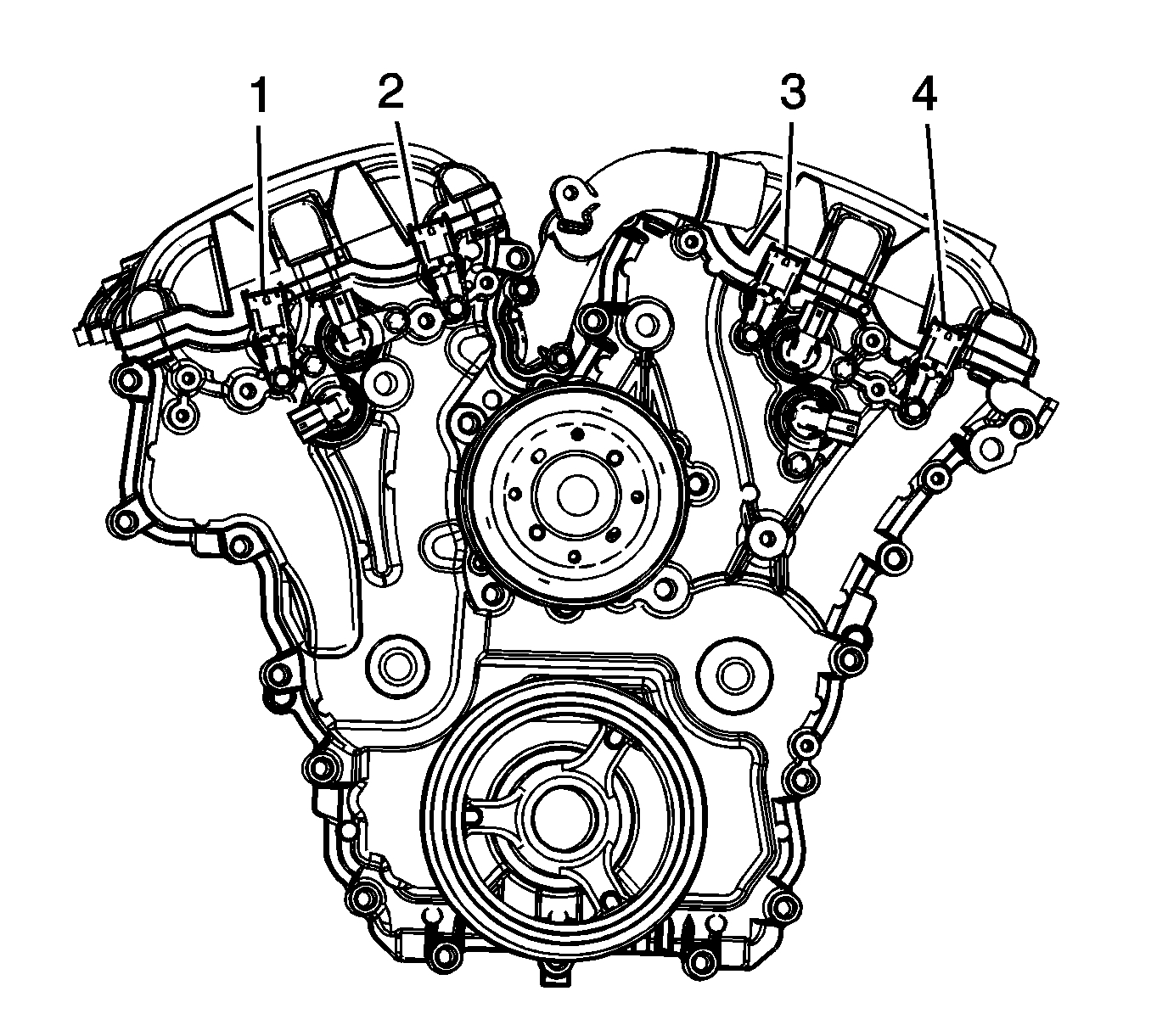
Remove the right intake and exhaust camshaft position sensors.
Remove the right intake and exhaust camshaft position actuator solenoids.
Important: Rotate the crankshaft balancer bolt in a clockwise direction ONLY.
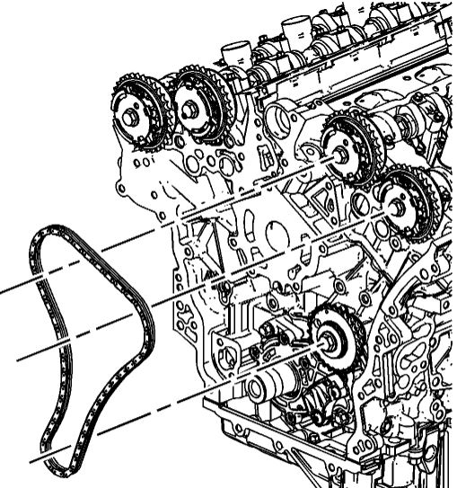
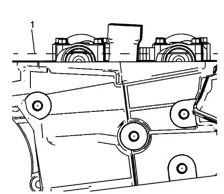
Rotate the crankshaft balancer using the balancer bolt until the camshafts are in a neutral (low tension) position. The camshafts will be parallel with the camshaft cover rail. Pic 3
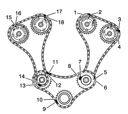
Important: Ensure that the camshaft timing chain and the camshaft position actuators are marked for proper assembly.
Use a paint stick to create an alignment mark (17) on one of the timing chain links and the adjacent tooth on the exhaust camshaft position actuator (18).
Use a paint stick to create an alignment mark (16) on one of the timing chain links and the adjacent tooth on the intake camshaft position actuator (15). Pic 4
Notice: A wrench must be used on the hex of the camshaft when loosening or tightening in order to prevent component damage. Failure to prevent the torque reaction against the timing drive chain can lead to timing drive chain failure.
Use an open end wrench on the hex cast into the left intake and exhaust camshafts and rotate the camshafts toward each other in order to create slack in the chain between the actuators.
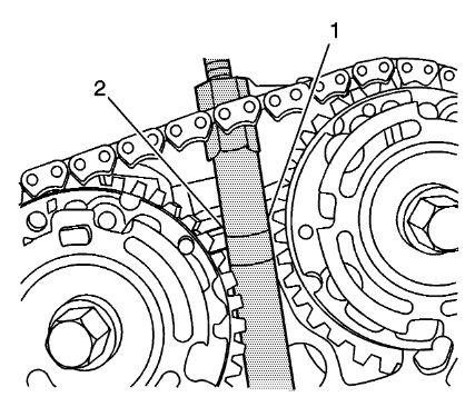
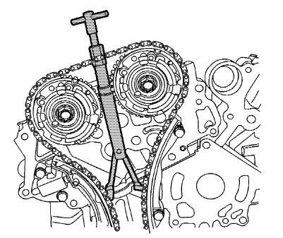
Unscrew the EN-48313 so that the legs of the tool are retracted and insert the EN-48313 between the camshaft actuators, rearward of the timing chain until the top line that is scribed in the body of the tool (1) is adjacent to the top surface of the cylinder head (2).
Pic 5
Important: The engine front cover is removed for clarity in the following graphics, but NOT required to perform the procedure.
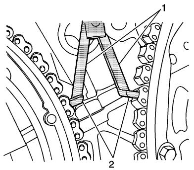
Ensure that the feet (2) on the legs of the tool are facing the front of the engine.
Partially expand the legs (1) of the EN-48313 by turning the T-shaped handle clockwise. and continue expanding the EN-48313 until the feet (2) contact the timing chain. Do not tighten at this time. Pic 6
Important: Ensure that the foot (1) of the EN-48313 is engaged into one of the link pockets to prevent chain slippage during tightening of the EN-48313. Do not allow the body of the EN-48313 to rotate when tightening the T-handle.
Hand tighten the EN-48313.
Use an open end wrench on the hex cast into the body of the EN-48313 and hand tighten the T-handle.
Use an open end wrench on the hex cast into the right intake and exhaust camshafts and rotate the camshafts towards each other in order to create slack in the chain between the actuators.
The EN-48313 is now properly installed to hold the timing chain in position. Pic 7
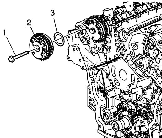
Use an open end wrench on the hex cast into the camshaft in order to prevent engine rotation when loosening the camshaft position actuator bolt.
Remove the right exhaust camshaft position actuator bolt.
Remove the right exhaust camshaft position actuator. When removing the actuator, place the chain on the engine cover side of the actuators. Pic 8
Rotate the actuator in order to align the opening in the actuator reluctor wheel with the cam sensor boss in the front cover, to allow actuator removal.
Images (Click to enlarge)
Feb 4, 2020 at 8:42 PM