That's the one I wanted you to try The P0411 is related to the secondary air injection. Take a look through this flow chart to see if it help.
_________________________________
2008 Buick Lucerne V6-3.8L
P0411
Vehicle ALL Diagnostic Trouble Codes ( DTC ) Testing and Inspection P Code Charts P0411
P0411
DTC P0411
Diagnostic Instructions
* Perform the Diagnostic System Check - Vehicle (See: Vehicle > Initial Inspection and Diagnostic Overview) prior to using this diagnostic procedure.
* ReviewStrategy Based Diagnosis (See: Vehicle > Initial Inspection and Diagnostic Overview) for an overview of the diagnostic approach.
* Diagnostic Procedure Instructions (See: Vehicle > Initial Inspection and Diagnostic Overview) provides an overview of each diagnostic category.
DTC Descriptor
DTC P0411
- Secondary Air Injection (AIR) System Incorrect Air Flow Detected
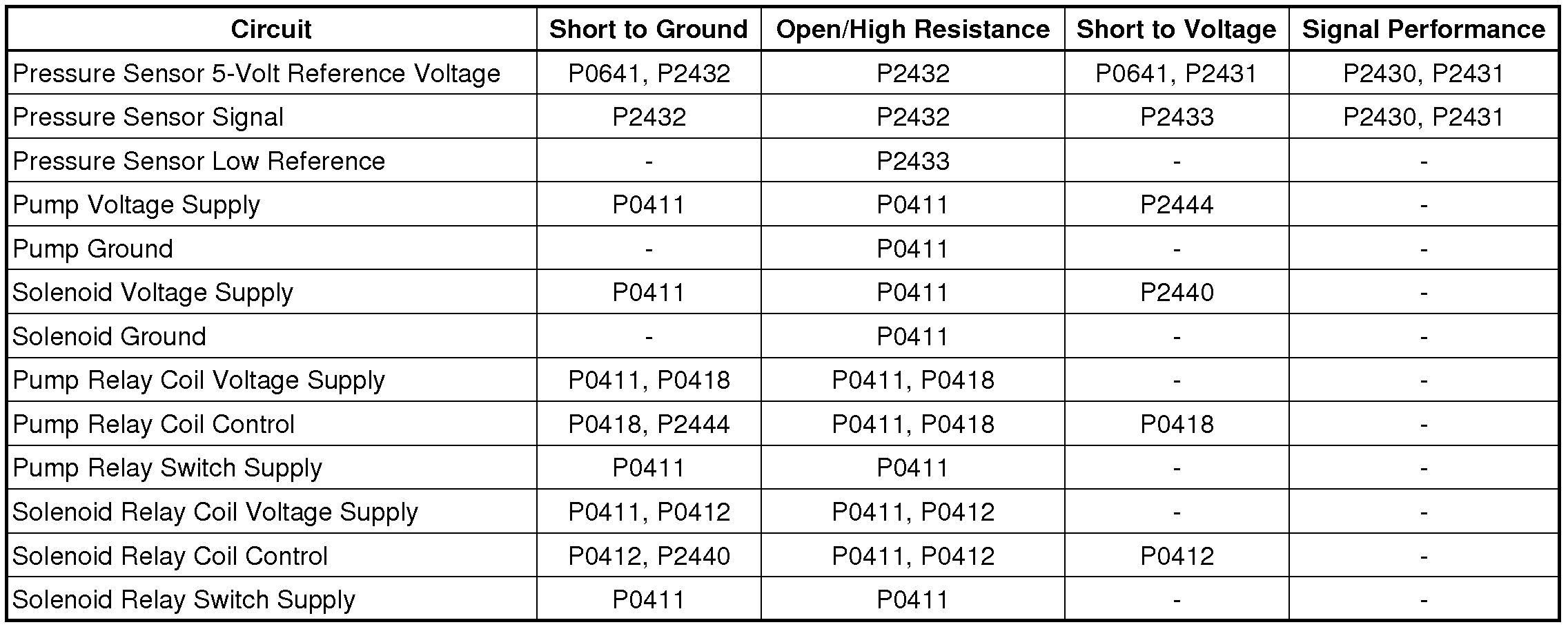
Diagnostic Fault Information
pic 1
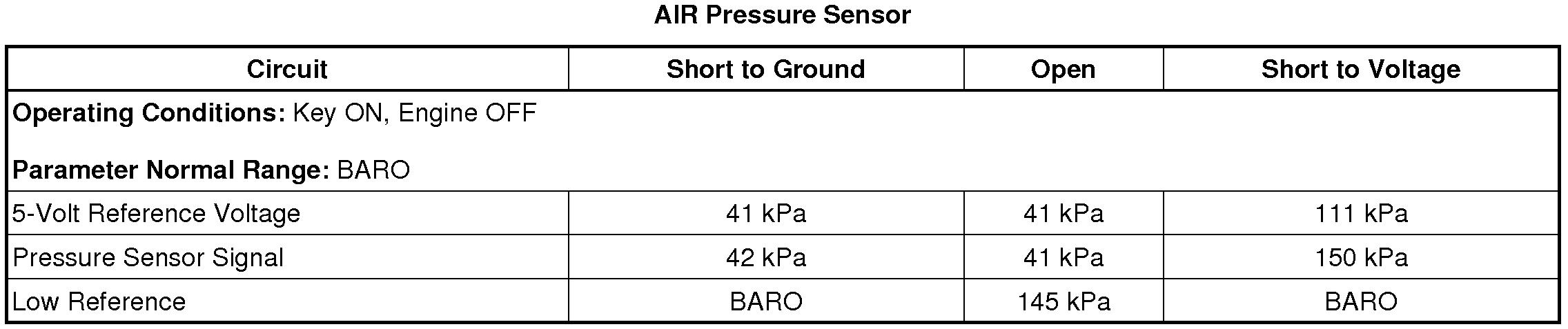
Typical Scan Tool Data
pic 2
Circuit/System Description
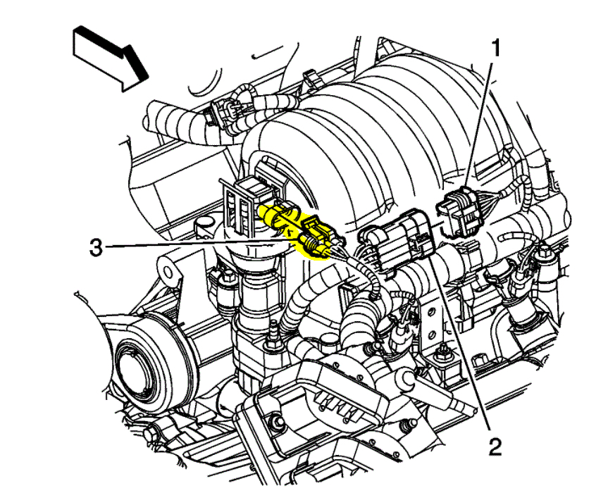
The secondary air injection (AIR) system aids in the reduction of hydrocarbon emissions during a cold start. The system forces fresh filtered air into the exhaust stream in order to accelerate the catalyst operation. An electric air pump, the secondary AIR injection pump, provides filtered air on demand to the AIR control solenoid valve/pressure sensor assembly. The AIR control solenoid valve/pressure sensor assembly controls the flow of air from the AIR pump to the exhaust manifold. The AIR valve relay supplies the current needed to operate the AIR control solenoid valve/pressure sensor assembly. A pressure sensor is used to monitor the air flow from the AIR pump. The powertrain control module (PCM) supplies the internal pressure sensor with a 5-volt reference, an electrical ground, and a signal circuit.
The AIR diagnostic uses 3 phases to test the AIR system:
1. DTCs P0411 and P2430 run during Phase 1.
2. DTCs P2430 and P2440 run during Phase 2.
3. DTC P2444 runs during Phase 3.
During phase 1, both the AIR pump and the solenoid valve are activated. Normal secondary air function occurs. Expected system pressure is 8-10 kPa above BARO.
During phase 2, only the AIR pump is activated. The solenoid valve is closed. Pressure sensor performance and solenoid valve deactivation are tested. Expected system pressure is approximately 15-22 kPa above BARO.
During phase 3, neither the AIR pump nor the solenoid valve is activated. AIR pump deactivation is tested. Expected system pressure equals BARO.
In all 3 phases, testing is accomplished by comparing the measured pressure against the expected pressure. The PCM can detect faults in the AIR pump, AIR control solenoid valve/pressure sensor assembly, and the exhaust check valve. The pressure sensor can also detect leaks and restrictions in the secondary AIR system plumbing.
Conditions for Running the DTC
* DTC P0101, P0102, P0103, P0107, P0108, P0112, P0113, P0116, P0117, P0118, P0201-P0206, P0300-P0306, P0350, P0412, P0418, P0420, P0606, P2430, P2431, P2432, P2433 are not set.
* The system voltage is 9-18 volts.
* The start-up engine coolant temperature (ECT) is between 5-50°C (41-122°F).
* The start-up intake air temperature (IAT) is between 5-60°C (41-140°F).
* The BARO parameter is more than 60 kPa.
* The MAF sensor parameter is between 3-24 g/s.
* The AIR system is commanded ON.
* The conditions are stable for more than 5 seconds.
* DTC P0411 runs once per trip start up when the above conditions are met and AIR pump operation is requested.
Conditions for Setting the DTC
* The difference between the predicted system pressure and the actual system pressure is more than 4 kPa.
* DTC P0411 sets within 22 seconds when the above condition is met.
Action Taken When the DTC Sets
DTC P0411 is a Type B DTC.
Conditions for Clearing the MIL/DTC
DTC P0411 is a Type B DTC.
Reference Information
Schematic Reference
Engine Controls Schematics (See: Powertrain Management > Electrical)
Connector End View Reference
Component Connector End Views (See: Vehicle > Connector Views)
Electrical Information Reference
* Circuit Testing (See: Vehicle > Component Tests and General Diagnostics)
* Connector Repairs (See: Vehicle > Component Tests and General Diagnostics)
* Testing for Intermittent Conditions and Poor Connections (See: Vehicle > Component Tests and General Diagnostics)
* Wiring Repairs (See: Vehicle > Component Tests and General Diagnostics)
* Relay Replacement (Attached to Wire Harness) (See: Power Distribution Relay > Removal and Replacement > Relay Replacement (Attached to Wire Harness))Relay Replacement (Within an Electrical Center) (See: Power Distribution Relay > Removal and Replacement > Relay Replacement (Within an Electrical Center))
DTC Type Reference
Powertrain Diagnostic Trouble Code (DTC) Type Definitions (See: A L L Diagnostic Trouble Codes ( DTC ) > Diagnostic Trouble Code Descriptions)
Scan Tool Reference
Control Module References (See: Vehicle > Programming and Relearning) for scan tool information
Circuit/System Verification
1. If any other AIR DTCs are set, perform those diagnostics first.
2. Inspect the AIR Solenoid outlet pipe for leaks.
3. Engine running, observe that the AIR Pressure Sensor parameter approximately equals barometric pressure (BARO).
4. Engine running, enable the AIR pump with a scan tool and observe that the AIR Pressure Sensor parameter equals approximately 15-20 kPa above BARO.
5. Engine running, enable the AIR solenoid with a scan tool and observe that the AIR Pressure Sensor parameter equals approximately 8-10 kPa above BARO.
6. Operate the vehicle within the Conditions for Running the DTC. You may also operate the vehicle within the conditions that you observed from the Freeze Frame/Failure Records data.
Circuit/System Testing
Important: Circuit/System Verification MUST be performed first or misdiagnosis may result.
1. Ignition ON, observe that the AIR pump is not activated.
If the AIR pump is activated, test the AIR pump voltage supply circuit for a short to voltage. If the circuit tests normal, test the AIR pump relay control circuit for a short to ground. If the circuits test normal, test the AIR pump relay. If the relay and circuits test normal, replace the PCM.
2. Ignition ON, enable the AIR pump with a scan tool and observe that the AIR pump is activated.
If the AIR pump is not activated, test the AIR pump voltage supply and ground circuits for more than 2 ohms of resistance. If the circuits test normal, test both AIR pump relay voltage supply circuits for an open/high resistance or a short to ground. If the circuits test normal, test the AIR pump relay control circuit for an open/high resistance or a short to voltage. If the circuits test normal, test the AIR pump relay. If the relay and circuits test normal, test the AIR pump. If the relay, pump, and circuits test normal, replace the PCM.
3. Ignition OFF, disconnect the harness connector at the AIR solenoid.
4. Connect a test lamp between the AIR solenoid voltage supply terminal 6 and ground circuit terminal 4.
5. Ignition ON, observe that the test lamp is not illuminated.
If the test lamp is illuminated, test the AIR solenoid valve voltage supply circuit for a short to voltage. If the circuit tests normal, test the AIR solenoid valve relay control circuit for a short to ground. If the circuits test normal, test the AIR solenoid valve relay. If the relay and circuits test normal, replace the PCM.
6. Enable the AIR solenoid with a scan tool and observe that the test lamp is illuminated.
If the test lamp is not illuminated, test the AIR solenoid voltage supply circuit and both AIR solenoid relay voltage supply circuits for an open/high resistance or a short to ground. If the circuits test normal, test the AIR solenoid ground circuit for an open/high resistance. If the circuits test normal, test both AIR solenoid relay control circuits for and open/high resistance or a short to voltage. If the circuits test normal, test the AIR solenoid relay. If the relay and circuits test normal, replace the PCM.
7. Ignition OFF, connect all wiring harness connectors.
8. Engine running, enable the AIR solenoid valve with a scan tool and observe that the AIR Pressure Sensor parameter equals approximately 8-10 kPa above BARO.
If not within the specified range, continue with this procedure.
9. Remove the AIR inlet hose from the AIR pump.
10. Engine running, enable the AIR solenoid valve with a scan tool and observe that the AIR Pressure Sensor Parameter increases to 8-10 kPa above BARO.
If within the specified range, the AIR pump inlet hoses/pipes are restricted. Remove the restriction or replace the hose/pipe.
If not within the specified range, continue with this procedure.
11. Disconnect the hose from the AIR pump outlet.
12. Disconnect the hose from the AIR solenoid valve inlet.
13. Install a length of standard 1 inch I.D. (25.4 mm) hose from the AIR pump outlet to the AIR solenoid valve inlet.
14. Engine running, enable the AIR solenoid valve with a scan tool and observe that the AIR Pressure Sensor Parameter increases to 8-10 kPa above BARO.
If within the specified range, the AIR pump outlet hoses/pipes are restricted or leaking. Remove the restriction or replace the hose/pipe.
If less than the specified range, replace the AIR pump.
If more than the specified range, continue with this procedure.
15. Remove the AIR solenoid valve.
16. Leave the standard hose and harness connector connected.
17. Engine running, enable the AIR solenoid valve with a scan tool and observe that the AIR Pressure Sensor Parameter increases to approximately 7 kPa above BARO.
If more than the specified value, replace the AIR solenoid valve.
If approximately the specified value, the exhaust system is restricted. Remove the restriction or replace the appropriate component.
Component Testing
Relay Test
1. Test between the normally-closed switch terminals, if any, for 0 ohms.
2. Test between the normally-open switch terminals for infinite ohms.
3. Test between each switch terminal and either coil terminal for infinite ohms.
4. Connect the relay coil terminals to ground and fused power to energize the relay.
5. Test between each switch terminal and each coil terminal for 0 volts.
6. Test between the normally-closed switch terminals, if any, for infinite ohms.
7. Test between the normally-open switch terminals for 0 ohms.
Pump
Connect the AIR pump to fused battery voltage and ground and observe pressurized airflow at the pump outlet.
If pressurized airflow is not observed, replace the pump.
Solenoid Valve
Apply fused battery voltage and ground to the solenoid and verify that the valve opens and closes completely as voltage is applied to and removed from the solenoid. Observe that the valve is not obstructed or leaking.
If the valve operates incorrectly, leaks, or is obstructed, remove the obstruction or replace the valve.
Repair Instructions
* Secondary Air Injection Pump Replacement (See: Air Injection Pump > Removal and Replacement > Secondary Air Injection Pump Replacement)
* Secondary Air Injection Shutoff and Check Valve Replacement (See: Air Injection Check Valve > Removal and Replacement > Secondary Air Injection Shutoff and Check Valve Replacement)
* Secondary Air Injection Pump Hose Replacement (See: Air Injection Hose/Tube > Removal and Replacement > Secondary Air Injection Pump Hose Replacement)
* Secondary Air Injection Feed Tube Replacement (See: Air Injection Hose/Tube > Removal and Replacement > Secondary Air Injection Feed Tube Replacement)
* Powertrain Control Module Replacement (See: Engine Control Module > Removal and Replacement) for control module replacement, setup, and programming
Repair Verification
1. With the ignition ON and the engine OFF, observe that the AIR pump is not operating.
2. With the engine running, enable the AIR solenoid with a scan tool and observe that the AIR Pressure Sensor parameter equals approximately 8-10 kPa above BARO.
3. With the engine running, enable the AIR pump with a scan tool and observe that the AIR Pressure Sensor parameter equals approximately 15-20 kPa above BARO.
________________
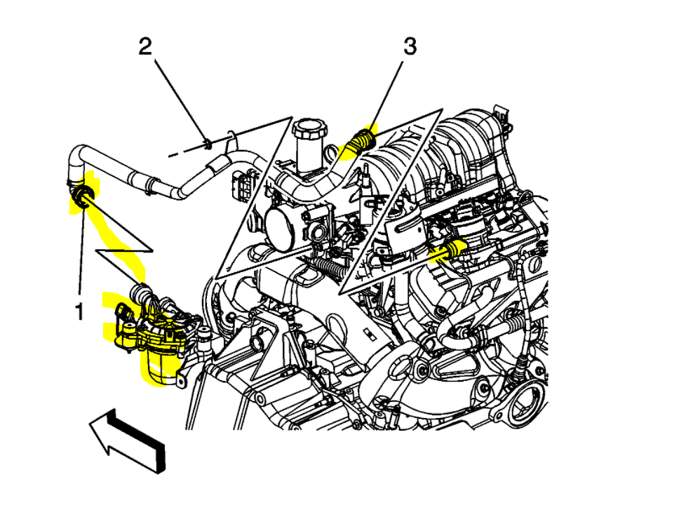
Also, pic 3 shows the pump location. Make sure the connectors I highlighted are tight and undamaged. That could be where the noise is coming from.
Just to reconfirm. This is the only code, correct?
Let me know.
Joe
Images (Click to enlarge)
Dec 2, 2020 at 5:48 PM