Engine is hard to start at cold and warm conditions

Tiny
PONTIMAN
  • MEMBER
  • 1991 PONTIAC BONNEVILLE
  • 3.8L
  • 6 CYL
  • 2WD
  • AUTOMATIC
  • 120,000 MILES
I need 3 to 20 times to fire it up, until it runs. If it runs, it is stumbling and often dies with a little backfire in the intake, so I've to restart it. When the car is running for a few minutes and the engine gets warmer, the stumbling is gone and it drives more or less, without any problems, but it seem to have low acceleration.
The car is very well maintained. I replaced any sensor around the engine and intake system, tested and changed the injectors, put new timing chain with gears and camshaft position sensor and magnet on it. All intake gaskets are new. No oil or cooling fluid gets burned. Sparks looks like there is a lean mixture problem (light grey powdered). Fuel pressure seems to be good, because if I push down the little valve at the fuel rail, the fuel sprays out to the open hood.
There are new spark plug wires and a new coil pack installed and also a new ICU. The ECM is also new.
The computer shows me a faulty cam sensor, but it got replaced 7 times (I tried the parts of all aftermarket manufacturers), but noting worked to get the that faulty code finally deleted. It always comes back during starting procedure.
I've also checked the wiring from cam and crank position sensor to ICU and ICU to ECM, but all looks good.
If you have any further ideas to eliminate the starting issue of my car, or to get permanently rid of the faulty code, I would appreciate your help.
Feel free to ask, if you need more details.
Many thanks
Sunday, August 16th, 2020 AT 5:39 AM

5 Replies

Tiny
ASEMASTER6371
  • MECHANIC
  • 52,797 POSTS
Good morning,

First, I need the code for the cam sensor? Can you give me the number?

I would start by checking the fuel pressure to be sure you have the correct amount of fuel to the rail for the injectors to work correctly.

https://www.2carpros.com/articles/how-to-check-fuel-system-pressure-and-regulator

https://www.2carpros.com/articles/engine-has-low-power-output

Roy
Was this
answer
helpful?
Yes
No
+1
Sunday, August 16th, 2020 AT 6:13 AM
Tiny
PONTIMAN
  • MEMBER
  • 15 POSTS
Hello Roy,

Many thanks for the fast reply.
I don't have a fuel pressure gauge, but will ask a shop nearby next week.

The faulty code of the cam position sensor is 041.
The car had this code stored when bought it, but it started and runs great for about 7 years. Now, suddenly I got the starting issue. :-(
Was this
answer
helpful?
Yes
No
Sunday, August 16th, 2020 AT 7:41 AM
Tiny
ASEMASTER6371
  • MECHANIC
  • 52,797 POSTS
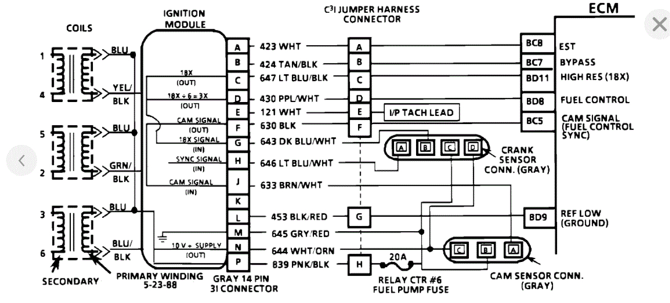
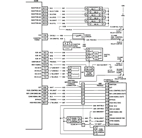
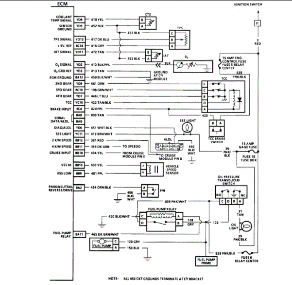
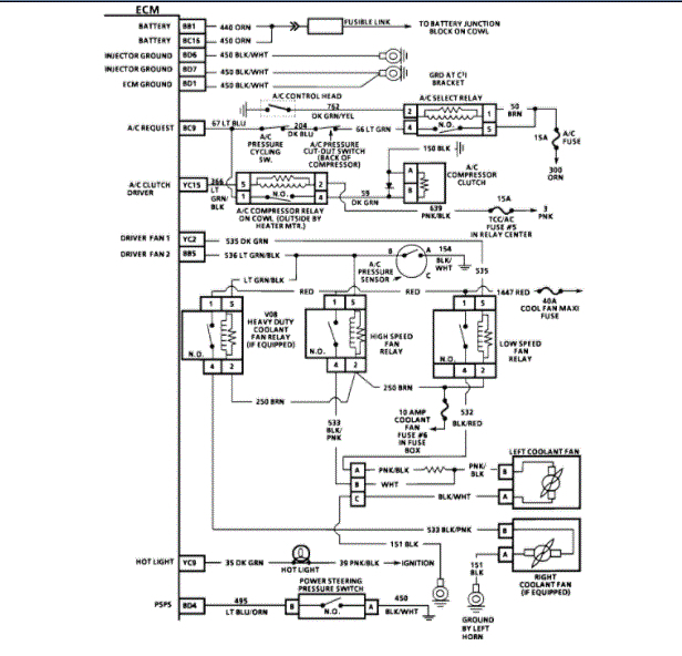
I attached the flow chart and wiring diagram for you of the system for the code 41.

Is the ABS light on by any chance?

You are welcome.

Roy

CIRCUIT DESCRIPTION:

During cranking, the ignition module monitors the dual crank sensor sync signal. The sync signal is used to determine the correct cylinder pair to spark first. After the sync signal has been processed by the ignition module it sends a fuel control reference pulse to the ECM. When the ECM receives this pulse it will command all six injectors to open for a (priming) shot of fuel in all cylinders. After the priming, the injectors are left "OFF" for the next six fuel control reference pulses (two crankshaft revolutions) from the ignition module. This allows each cylinder a chance to use the fuel from the (priming) shot. During this waiting period, a cam pulse will have been received by the ECM. Now the ECM begins to operate the injectors sequentially, based on true camshaft position. However, if the cam signal is not present at start-up a code 41 will be set and the ECM will start sequential fuel delivery in any old random pattern. The engine has a 1 in 6 chance that fuel delivery is correct.

Code 41 sets when the following conditions are met:

Engine is running.
Cam sensor signal not received by by the ECM in last 2 seconds.

NOTE: Because of all the possible color code combinations used on electrical wiring diagrams, always refer to ECM CONNECTOR IDENTIFICATION under ELECTRICAL AND ELECTRONIC WIRING DIAGRAMS for correct color code identification of circuit.

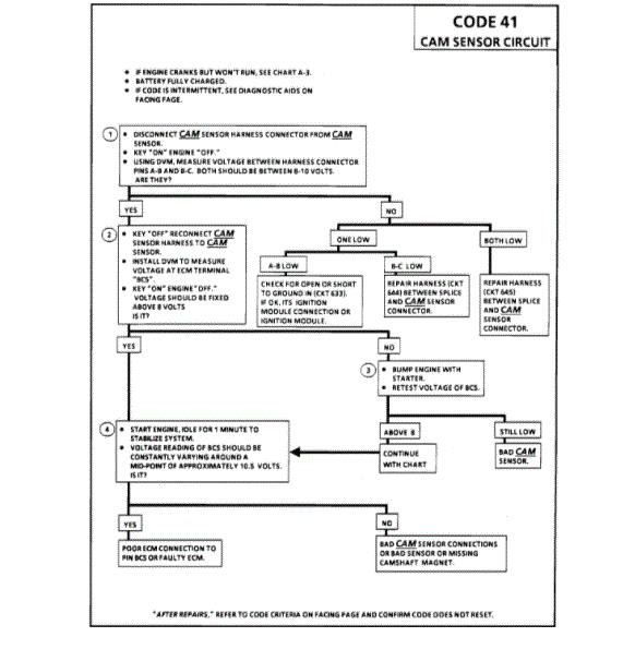
TEST DESCRIPTION: Numbers below refer to circled numbers on the diagnostic chart.

1. This step verifies proper operation of CKTs 633, 644, and 645.

2. Step validates the integrity of CKT 630 from C3I module to ECM.

3. If the camshaft gear magnet is interfacing with the cam sensor the voltage reading will be zero, bumping engine will cause the condition to go away.

4. If the voltage reading of "BC5" is constantly varying and connection to terminal "BC5" are good, the ECM is faulty.

DIAGNOSTIC AIDS:

An intermittent may be caused by a poor connection, rubbed through wire insulation or a wire broken inside the insulation.

Check For:

Poor Connection or a damaged Harness inspect ECM harness connectors for backed out terminal "BC5, " improper mating, broken locks, improperly formed or damaged terminals, poor terminal to wire connection and damaged harness.

Intermittent Test If connections and harness check okay, monitor a digital voltmeter connected from ECM terminal "BC5" to ground while moving related connectors and wiring harness. If the failure is induced, the voltage reading will change. This may help to isolate the location of the malfunction.
Was this
answer
helpful?
Yes
No
Sunday, August 16th, 2020 AT 7:51 AM
Tiny
PONTIMAN
  • MEMBER
  • 15 POSTS
Hello Roy,

I spent a lot time on trouble shot my car along your instructions.

Regarding the fuel pressure: I couldn't get a fuel pressure gauge, which fits the tire vent in the fuel rail next to the injectors, but I bought a second Pontiac Bonneville. It's a SSE and both cars look more ore less like twins.

I checked the fuel pressure with a screwdriver on both cars, and there is less fuel pressure at the SE, than the SSE has. So I ordered a new fuel pump. It's still on it's way from the US to Germany and will hopefully arrive next week.

I also figured out, that there is sometimes no spark at the coil pack. I swapped ECM, ICM, cam sensor, crank sensor and also the little wiring harness which is plugged to the sensors, ICM and ends in an 8 pin plug next to the power steering pump.
At the end, the SSE runs great with the parts from the SE and the SE don't runs with the parts taken from the SSE. This tells me, that all these parts are in good state and not causing any trouble.

Now, I started to check all wires from the 3 plugs connected to the ECM. I figured out, that there are 3 wires the SSE has a voltage reading and the SE don't have any voltage reading

My question are:
Are you able to send me a full wiring diagram of the 1991 Pontiac Bonneville, especially the ECM wiring.
I'm also interested in knowing, what for the three relays mounted next to the air cleaner box.

Many thanks for your help. I will keep you up to date. ;-)
Was this
answer
helpful?
Yes
No
Friday, August 28th, 2020 AT 8:50 AM
Tiny
ASEMASTER6371
  • MECHANIC
  • 52,797 POSTS
Okay, I attached the pin out of the ECM for you.

Can you post a picture of the relay that you see?

Roy
Was this
answer
helpful?
Yes
No
Friday, August 28th, 2020 AT 9:01 AM

Please login or register to post a reply.

Sponsored links