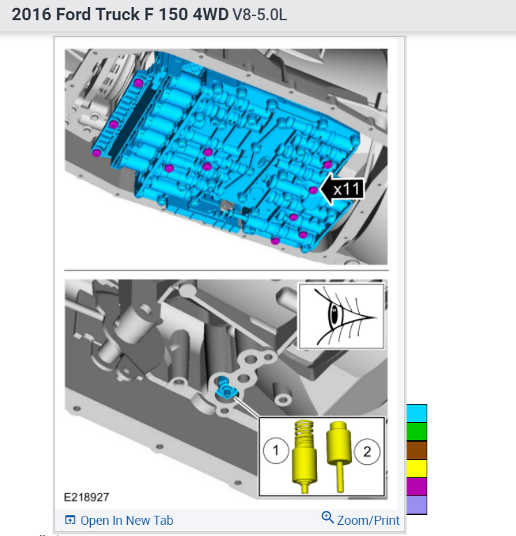
Yep, saving money is the game these days, there is a bit of confusion here, we don't show an output shaft speed sensor in these trucks since 2010? and i can't find one on Rockauto either. Nevertheless, here is how to remove the valve body. Please let me know what you find.
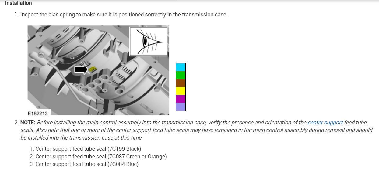
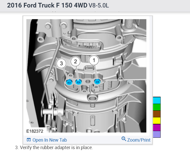
Here are the instructions and locations for replacing the transmission output speed sensor in the diagrams and text below. It does not say where the sensor is, but I assume it is on the valve body or underneath it.
Best Test Location:
Transmission case 16 pin lead frame connector located at right rear of transmission.
The PCM controls the electronic functions of this transmission. OSS sensor is part of the plastic molded lead frame bolted to the main control assembly inside the transmission.
The lead frame also contains the Turbine Shaft Speed (TSS), Output Shaft Speed (OSS), Transmission Fluid Temperature (TFT) and Transmission Range (TR) sensors.
Adaptive Learning Drive Cycle
Configuration
NOTE: Perform the adaptive learning drive cycle on a level road surface.
NOTE: The engine and transmission must be at normal operating temperature with the transmission fluid at the correct level.
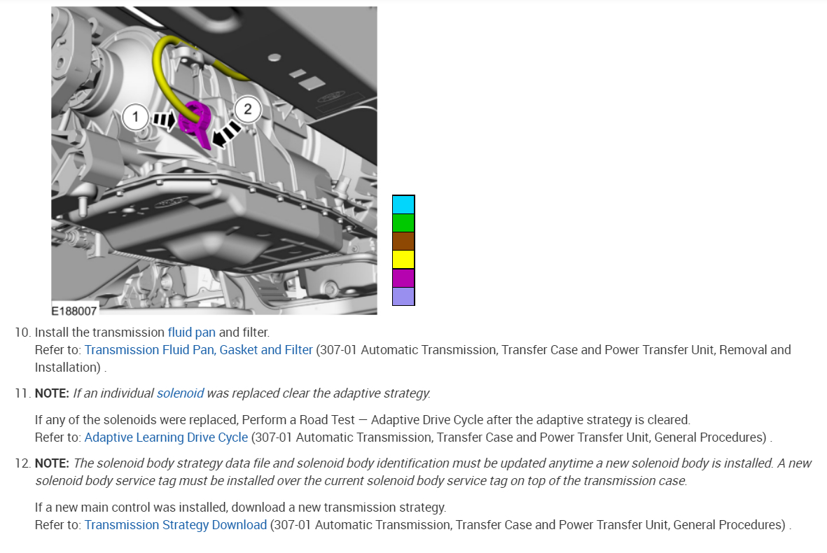
Record then clear the DTCs (Diagnostic Trouble Codes).
Warm the engine and transmission to normal operating temperature.
With the selector lever in (D), moderately accelerate from stop to 80 km/h (50 mph) allowing the transmission to shift into 6th gear. Keep vehicle speed and throttle steady for a minimum of 15 seconds.
With the transmission in 6th gear and maintaining steady speed and throttle, lightly apply and release the brake to operate stop lamps. Maintain the speed and throttle for a minimum of 5 seconds.
Brake to a stop and remain stopped for a minimum of 20 seconds.
Repeat Steps 3 through 5 five times.
Transmission Strategy Download
Programming
If a new main control was installed, record the 12-digit solenoid body identification and 13-digit solenoid body strategy from the replacement solenoid body tag provided with the main control service kit. Place the replacement tag over the existing identification tag.
13 - digit solenoid body strategy
12 - digit solenoid body identification
image
Using the scan tool, select module Programming and Programmable Parameters under the toolbox icon and select transmission. Follow the instructions displayed on the scan tool. There are fields to enter the solenoid body 12-digit identification and 13-digit strategy recorded from the solenoid body.
Compare the transmission strategy label to the codes displayed on the scan tool. The codes displayed on the scan tool should match the label. If not, select the update option on the tool. Once the update option is selected the tool will ask the user what best describes the repair operation that was performed on the transmission. The scan tool will only allow the user to select 1 of the five options. Once the selection is made, the user can enter the transmission code from the label into the entry box.
NOTICE: If the solenoid body information is not correct, transmission damage or drivability concerns can occur.
NOTICE: It is critical that only 13-digit strategy be entered into the scan tool. Entering the 12-digit solenoid body identification will result in partial file download to the module. The 12-digit solenoid body identification option should only be used when directed by engineering in a case where a full 13-digit strategy cannot be obtained.
Enter the solenoid body 13-digit strategy. The scan tool verifies the numbers entered are valid and displays a message if the information is not valid. The scan tool will check to verify the file is present on the scan tool. If the file is present, the technician may proceed with downloading the file to the module. If the file is NOT present, the scan tool will promt the user for permission to retrieve the file from the Professional Technician Society (PTS) server. Internet access will be required to download the file from the server to the scan tool.
Follow the instructions on the network to download the strategy file to the scan tool.
Follow the instructions displayed on the scan tool.
The scan tool automatically downloads the strategy file. The scan tool displays a message when it is finished downloading the data that states that the file was downloaded successfully.
NOTICE: If a driving cycle is not completed, erratic shifts and drivability concerns may occur.
Road test the vehicle following the Adaptive Learning Drive Cycle.
Refer to: Adaptive Learning Drive Cycle (307-01 Automatic Transmission, Transfer Case and Power Transfer Unit, General Procedures) .
Check out the diagrams (below). Please let us know what you find. We are interested to see what it is.
Images (Click to enlarge)
May 3, 2022 at 11:45 AM