Wiring diagram for the speedometer and odometer needed

Tiny
RD66
  • MEMBER
  • 2008 KIA SPECTRA
  • 2.0L
  • 4 CYL
  • 2WD
  • MANUAL
  • 100,000 MILES
I need a diagram that explains what wire runs the speedometer and odometer.
Monday, April 11th, 2022 AT 8:05 PM

21 Replies

Tiny
KASEKENNY
  • MECHANIC
  • 18,907 POSTS
I am attaching the wiring diagrams on these systems. However, if you have an issue with the speedometer and odometer then let's start with checking for codes.

https://www.2carpros.com/articles/checking-a-service-engine-soon-or-check-engine-light-on-or-flashing

The only reason is the speedometer gets this signal from the ABS module, and it calculates the mileage based on this signal.

If there is an issue, then more than likely we have some codes so I would suggest we start with this.

Please see the wiring diagrams below and let us know what other info you need.

Thanks
Was this
answer
helpful?
Yes
No
+1
Tuesday, April 12th, 2022 AT 8:15 PM
Tiny
RD66
  • MEMBER
  • 61 POSTS
The only code I have is the airbag. The ABS light did come on when this first happened. I changed the VSS sensor on the transmission. And one wheel speed sensor. Light went out and I have no ABS code. But the speedometer, odometer, front parking light, and now the cluster lights have gone out. I was having a problem with the headlights because the relays were not closing. But there working now. I'm wondering if I have a light switch going bad.
Was this
answer
helpful?
Yes
No
Tuesday, April 12th, 2022 AT 8:26 PM
Tiny
RD66
  • MEMBER
  • 61 POSTS
The wire colors don't match my car in those diagrams you gave me.
Was this
answer
helpful?
Yes
No
Wednesday, April 13th, 2022 AT 4:22 PM
Tiny
KASEKENNY
  • MECHANIC
  • 18,907 POSTS
Okay. Thanks for the update.

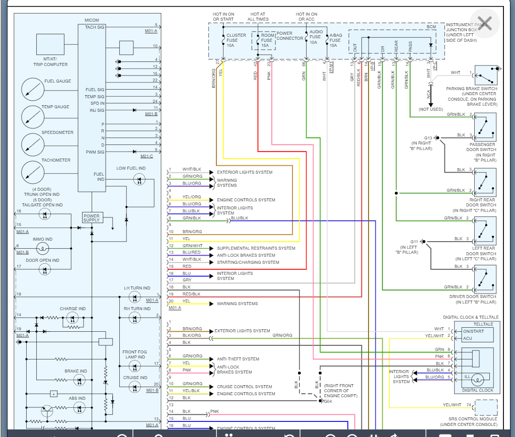
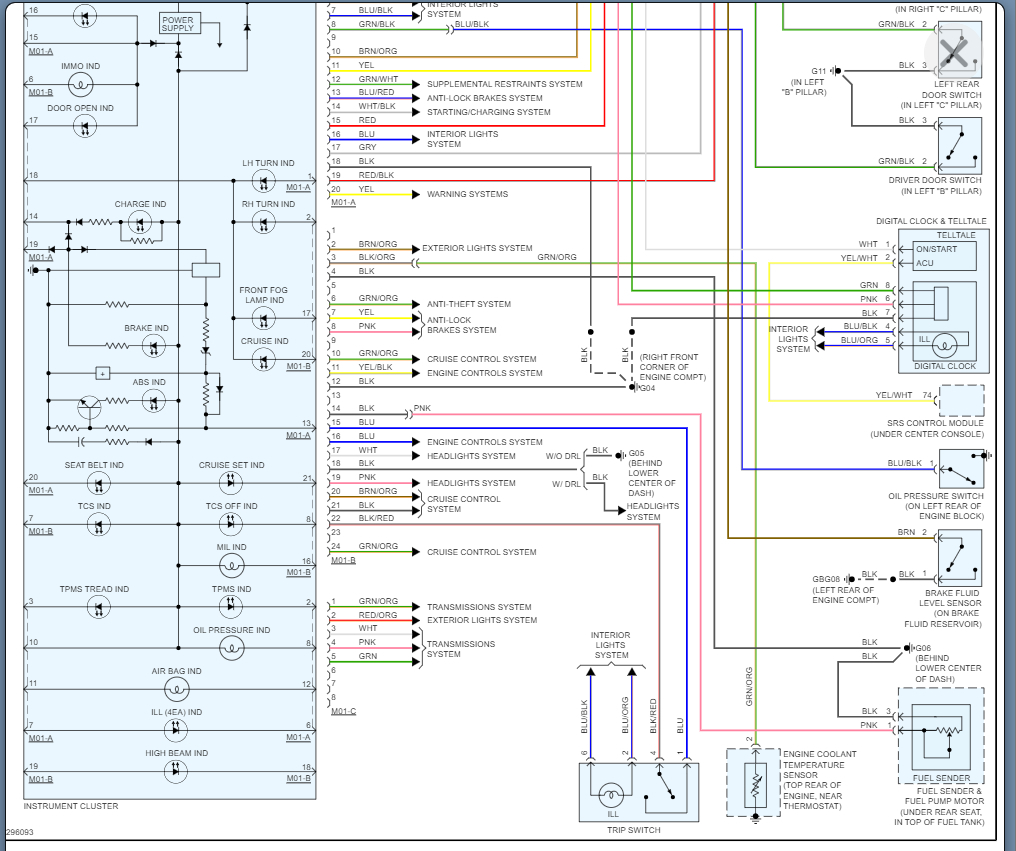
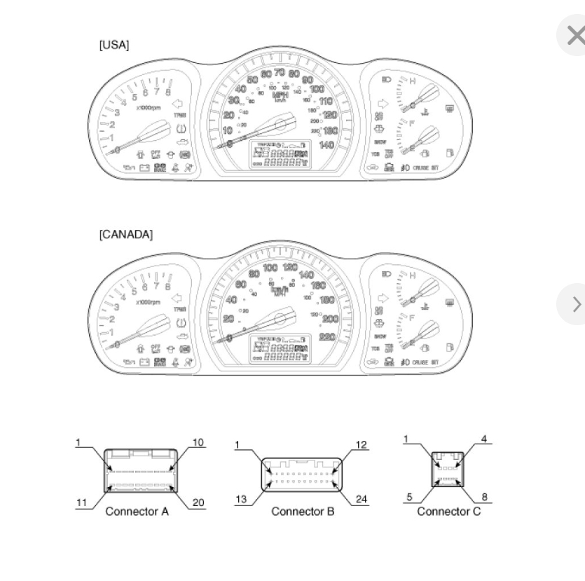
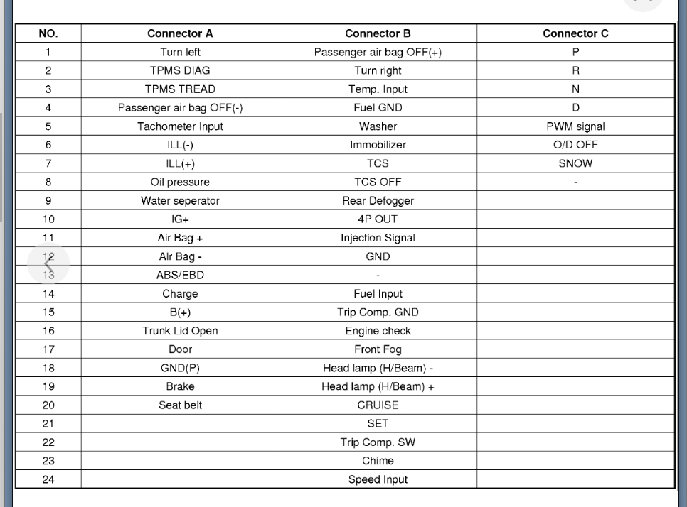
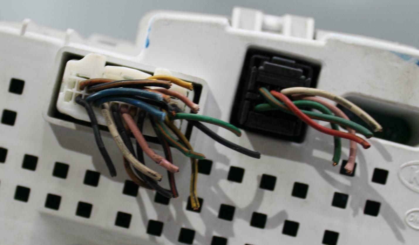
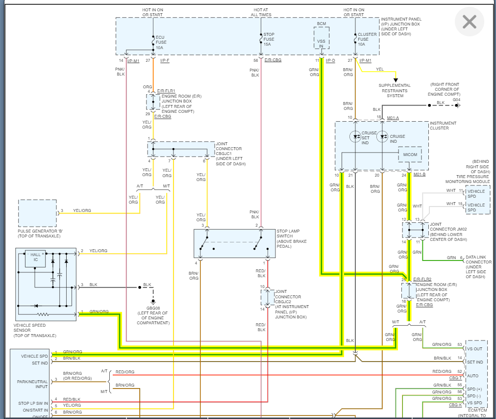
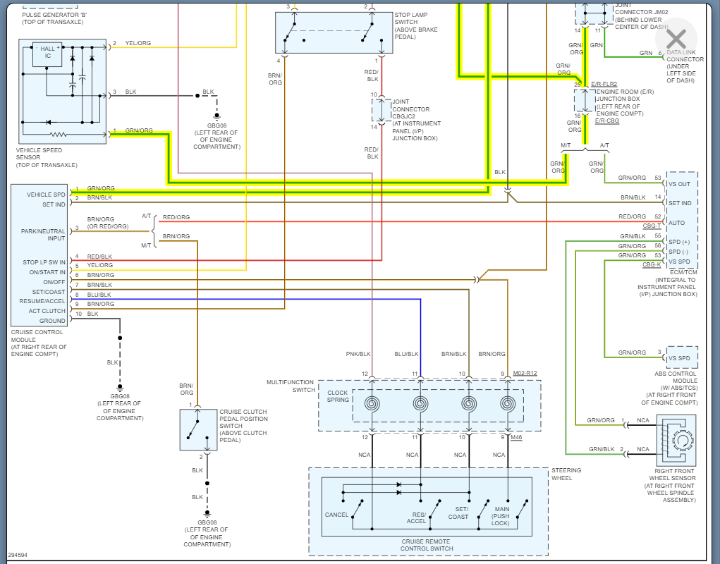
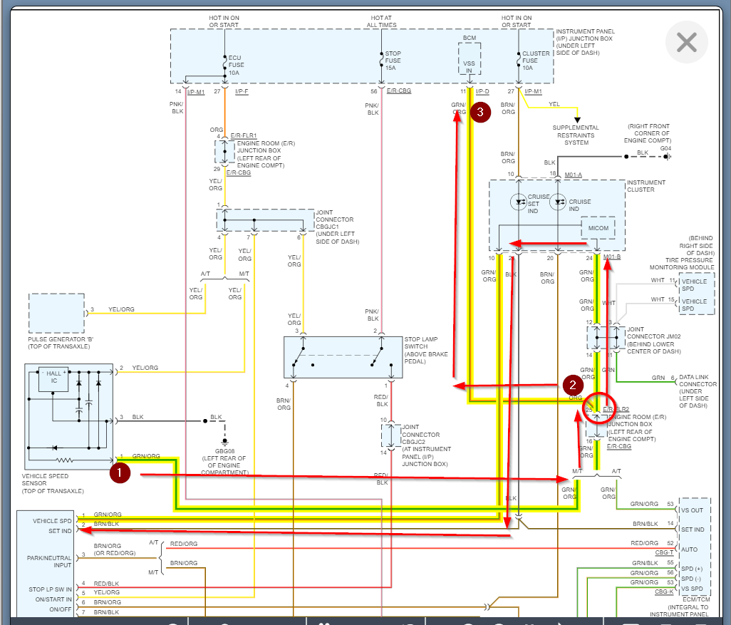
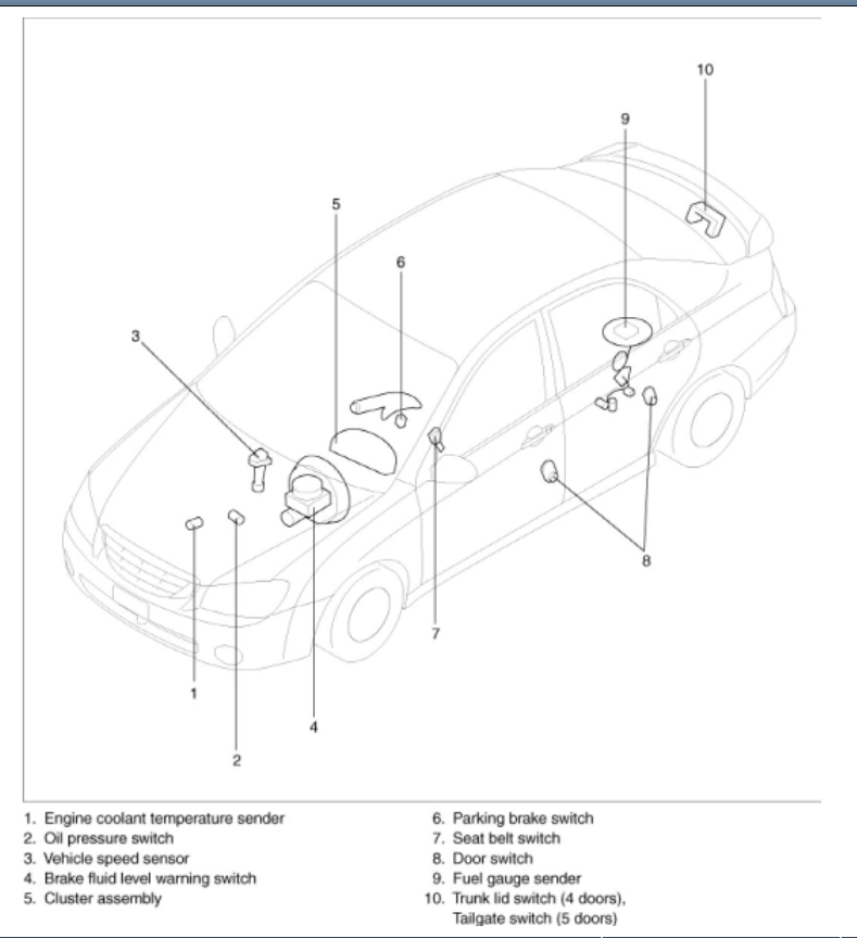
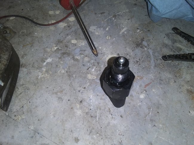
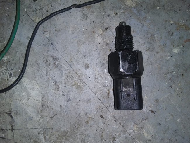
I would not worry so much about the wiring colors. As long as your connectors are matching the connectors shown below, the colors may be different.

Basically, what happens is when the OEM runs out of one color wire, they make a change, but the wiring diagrams will only show the color that it was originally.

Also, if someone changes the harness then the colors could be different as well.
Was this
answer
helpful?
Yes
No
+2
Thursday, April 14th, 2022 AT 3:38 PM
Tiny
RD66
  • MEMBER
  • 61 POSTS
Okay. Connector c is on my cluster but there's no harness to it. The other two pins in your diagram marches mine. Now, I located pin 24 on the harness at the cluster and ran a continuity test from the cluster to the transmission speed sensor. I get continuity from the cluster to a connector in the kick panel, but I don't get it all the way to the transmission.
I get nothing at the ECM plugin. I don't get anything from the ECM to the transmission, or the cluster. I need to know the path the current takes from the Transmission to the cluster.
So, I can trace the complete circuit.
Was this
answer
helpful?
Yes
No
Thursday, April 14th, 2022 AT 6:22 PM
Tiny
RD66
  • MEMBER
  • 61 POSTS
I guess I don't have harness c because my car is a standard transmission. Does the odometer run off the same current as the speedometer?
Was this
answer
helpful?
Yes
No
Thursday, April 14th, 2022 AT 6:34 PM
Tiny
RD66
  • MEMBER
  • 61 POSTS
BTW, that green wire with the orange strip is the same color as the wire on the speed sensor. If you're looking at the front of the cluster that pin is bottom left. The 24 pin in the pic you sent is bottom right. Does that matter?
Was this
answer
helpful?
Yes
No
Thursday, April 14th, 2022 AT 6:45 PM
Tiny
KASEKENNY
  • MECHANIC
  • 18,907 POSTS
I am attaching the diagram below. Due to this being a Manual transmission it does not run to the ECM. Only auto transmission goes to the ECM/TCM.

If you have signal getting to the Cluster, then the cluster is the issue.
Was this
answer
helpful?
Yes
No
+1
Friday, April 15th, 2022 AT 6:45 PM
Tiny
RD66
  • MEMBER
  • 61 POSTS
Thank you, will let you know what I find.
Was this
answer
helpful?
Yes
No
Friday, April 15th, 2022 AT 7:25 PM
Tiny
RD66
  • MEMBER
  • 61 POSTS
Can you show me the direction of flow? And does the transmission speed sensor need to be turning to get voltage at the cluster?
Was this
answer
helpful?
Yes
No
Friday, April 15th, 2022 AT 7:40 PM
Tiny
KASEKENNY
  • MECHANIC
  • 18,907 POSTS
Take a look at the diagram. There are two paths for this signal but they both start at the vehicle speed sensor.

Yes. These are signal circuits so if the vehicle is not moving then you likely have little to no voltage.

The circled location is the split but the path that is number is the one for the speedometer. The other is for the cruise control.
Was this
answer
helpful?
Yes
No
Saturday, April 16th, 2022 AT 7:32 AM
Tiny
RD66
  • MEMBER
  • 61 POSTS
So where is the speedometer in this diagram?
Was this
answer
helpful?
Yes
No
Saturday, April 16th, 2022 AT 8:52 AM
Tiny
KASEKENNY
  • MECHANIC
  • 18,907 POSTS
I am not sure why they made the diagram this way but if you look at the cluster where it says VSS in, that is the input to the cluster for the vehicle speed. The "BCM" uses this to operate the speedometer.

If you look at the diagram of the cluster in my first response you will see where the circuits are going into a module that is within the cluster. Basically, this is a logic module that takes the input, converts it so that it can be displayed on the speedometer.

This is why if you have a signal on these circuits then the cluster is the issue.
Was this
answer
helpful?
Yes
No
Saturday, April 16th, 2022 AT 4:34 PM
Tiny
RD66
  • MEMBER
  • 61 POSTS
I understand. Let me ask you this: what is this sensor next to the clutch cylinder?
Was this
answer
helpful?
Yes
No
Saturday, April 16th, 2022 AT 5:08 PM
Tiny
RD66
  • MEMBER
  • 61 POSTS
Hers another view.
Was this
answer
helpful?
Yes
No
Saturday, April 16th, 2022 AT 5:18 PM
Tiny
KASEKENNY
  • MECHANIC
  • 18,907 POSTS
Hard to say. It looks like the location of where the vehicle speed sensor should be.

I would have a better idea if I saw the actual sensor removed from the unit.
Was this
answer
helpful?
Yes
No
Saturday, April 16th, 2022 AT 5:18 PM
Tiny
RD66
  • MEMBER
  • 61 POSTS
The speed sensor is on the back side next to the firewall. Does manual transmission have an input and an output sensor? The one on the back has three wires, the one in front has 2 wires. On a different note, I have an Evap code PO453 Evaporative Control System Pressure Sensor High Input. I tested the pressure sensor, I'm getting 5 volts to it. And I probed the yellow wire and got 2.5 volts, but when I added vacuum, the reading went up instead of down. It's supposed to go down, right?
Was this
answer
helpful?
Yes
No
Saturday, April 16th, 2022 AT 6:40 PM
Tiny
RD66
  • MEMBER
  • 61 POSTS
It's the backup light switch.
Was this
answer
helpful?
Yes
No
Saturday, April 16th, 2022 AT 9:32 PM
Tiny
KASEKENNY
  • MECHANIC
  • 18,907 POSTS
Great job. Yep. Manual does not have input and output, but you got it.

Thanks for the pictures. That really helps others in the future that view this.
Was this
answer
helpful?
Yes
No
Sunday, April 17th, 2022 AT 10:20 AM
Tiny
RD66
  • MEMBER
  • 61 POSTS
Can you show me the wires for the dash lights? They don't work either.
Was this
answer
helpful?
Yes
No
Sunday, April 17th, 2022 AT 10:44 PM

Please login or register to post a reply.

Sponsored links