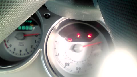
Hi and thanks for using 2carpros.com.
I have to be honest, this isn't going to necessarily be an easy fix.
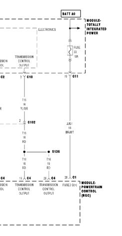
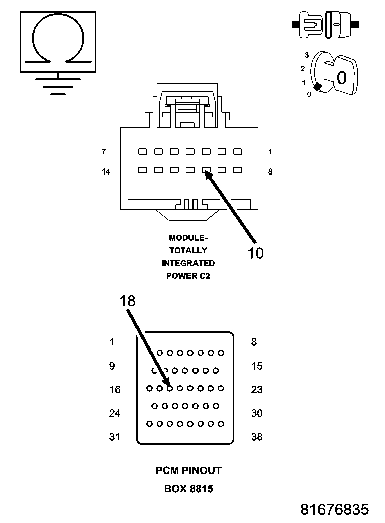
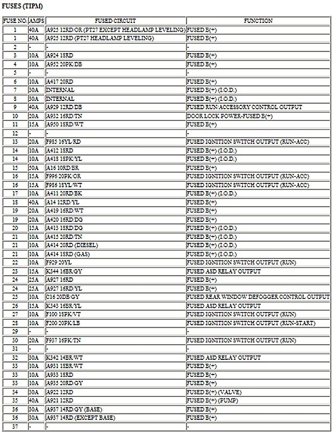
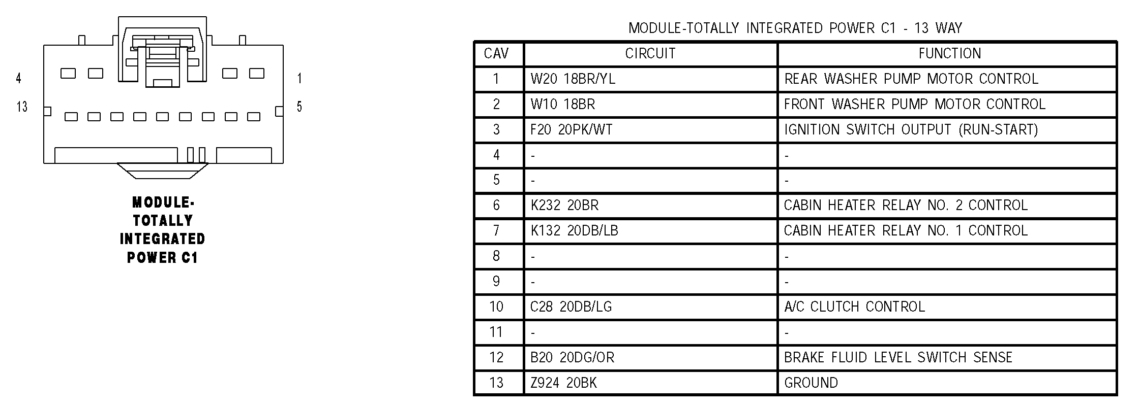
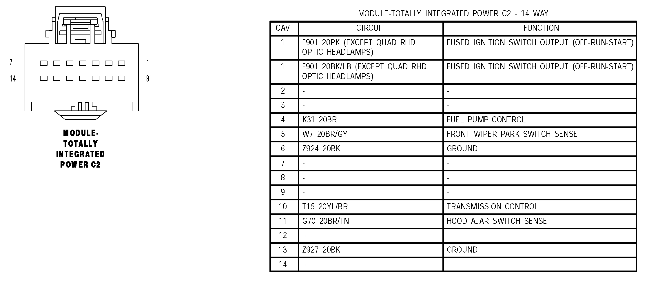
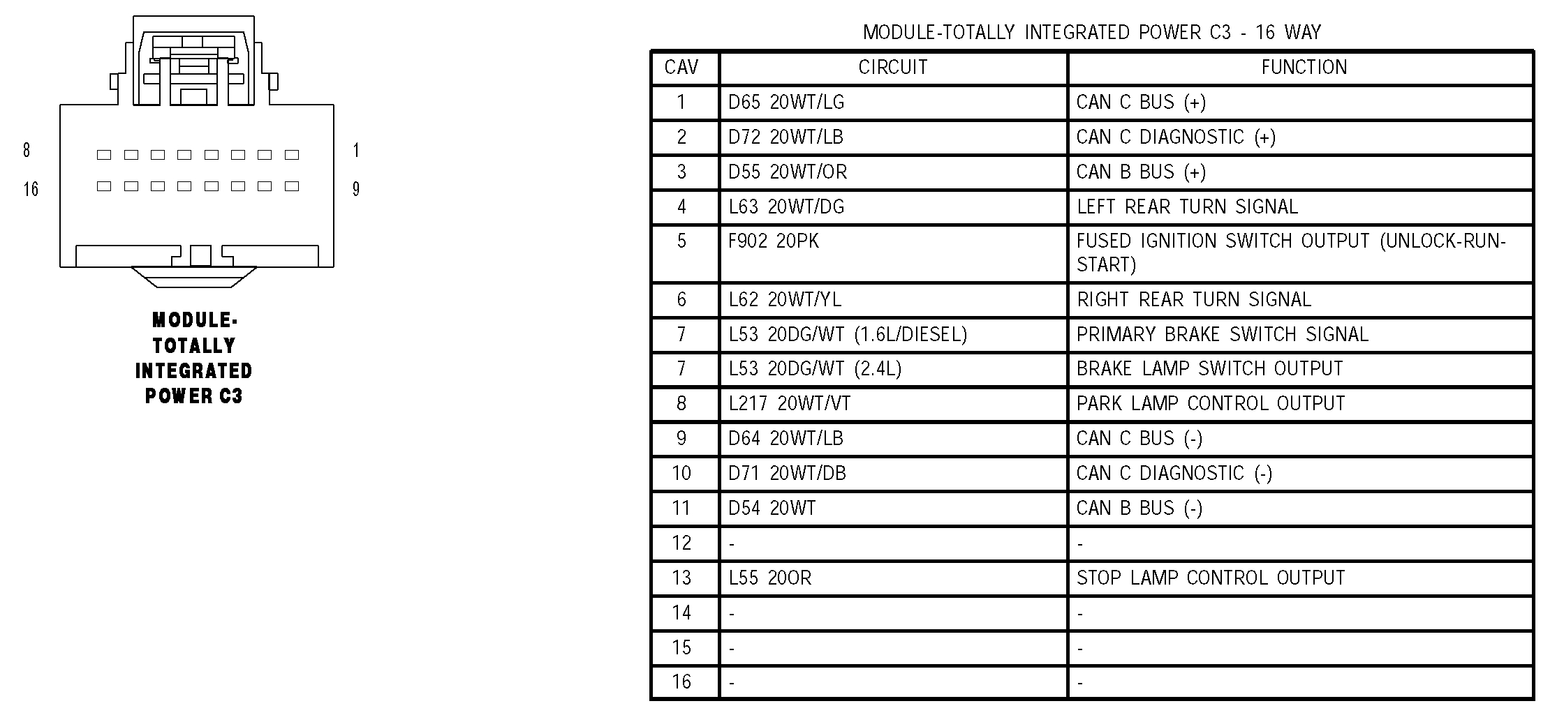
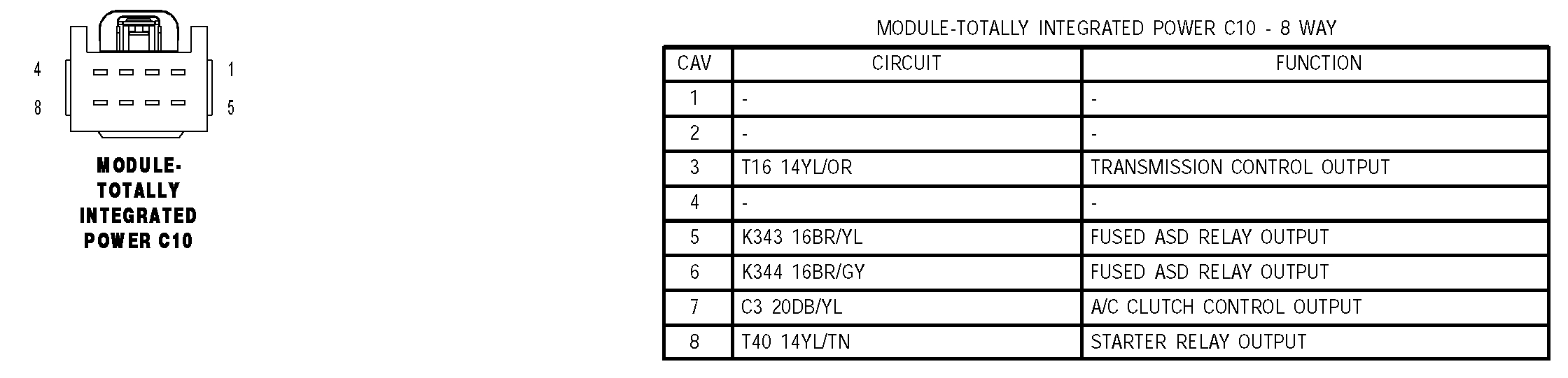
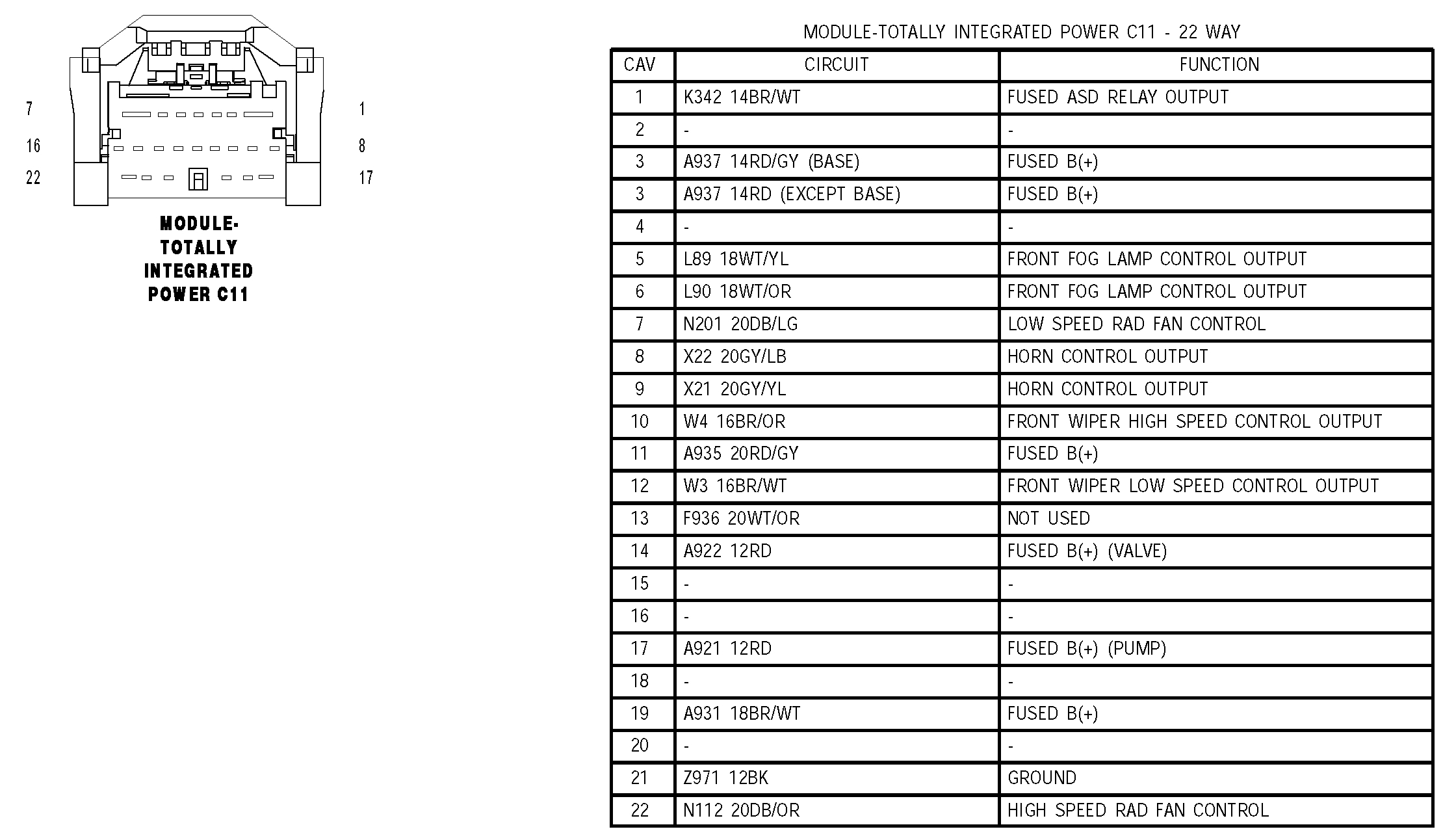
The code you are getting indicates low power to the power control module (PCM). I have a feeling that I may know what is happening and it isn't uncommon. These vehicle have a totally integrated power module (TIPM). If you look at picture 1, you will see that power to the PCM is supplied via the TIPM via the B+ power supply, C connector pin 11. From there, power runs through the power-train control module (PCM) transmission output. See picture 2. That is where the power supply is too low and it sets the code. Now, the TIPM's have several tiny pins that supply power to different components. What I have seen happen is this. Due to corrosion and normal usage, the pins will corrode or break. Then, you end up with low voltage, no voltage, or a false positive. Basically you see voltage with a meter, but when a load is placed on it, the circuit fails.
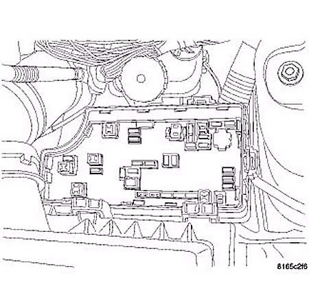
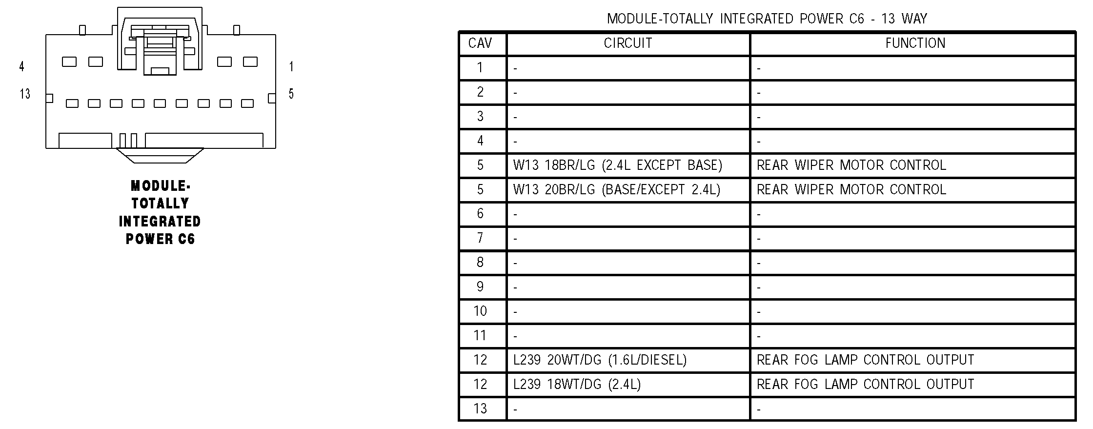
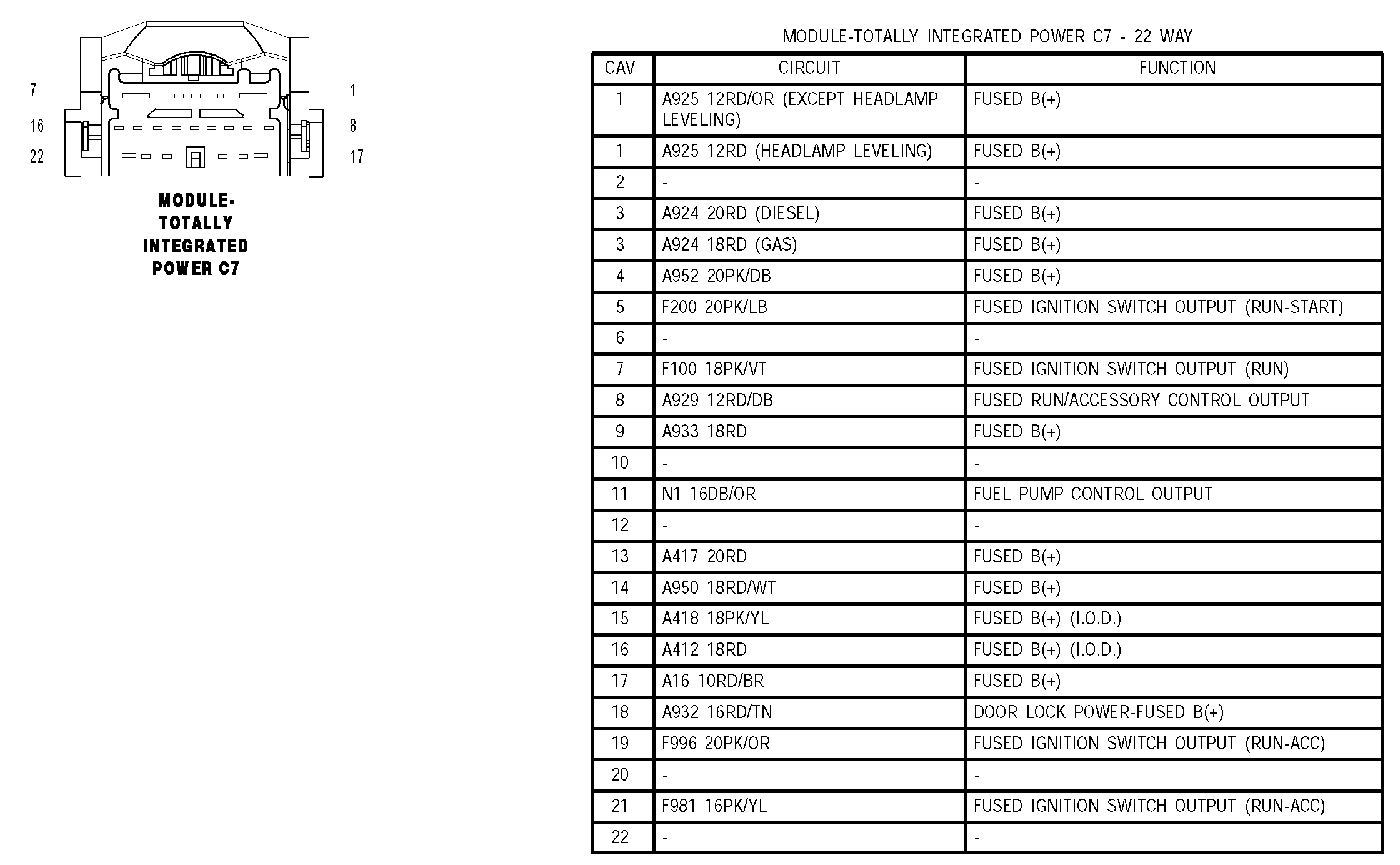
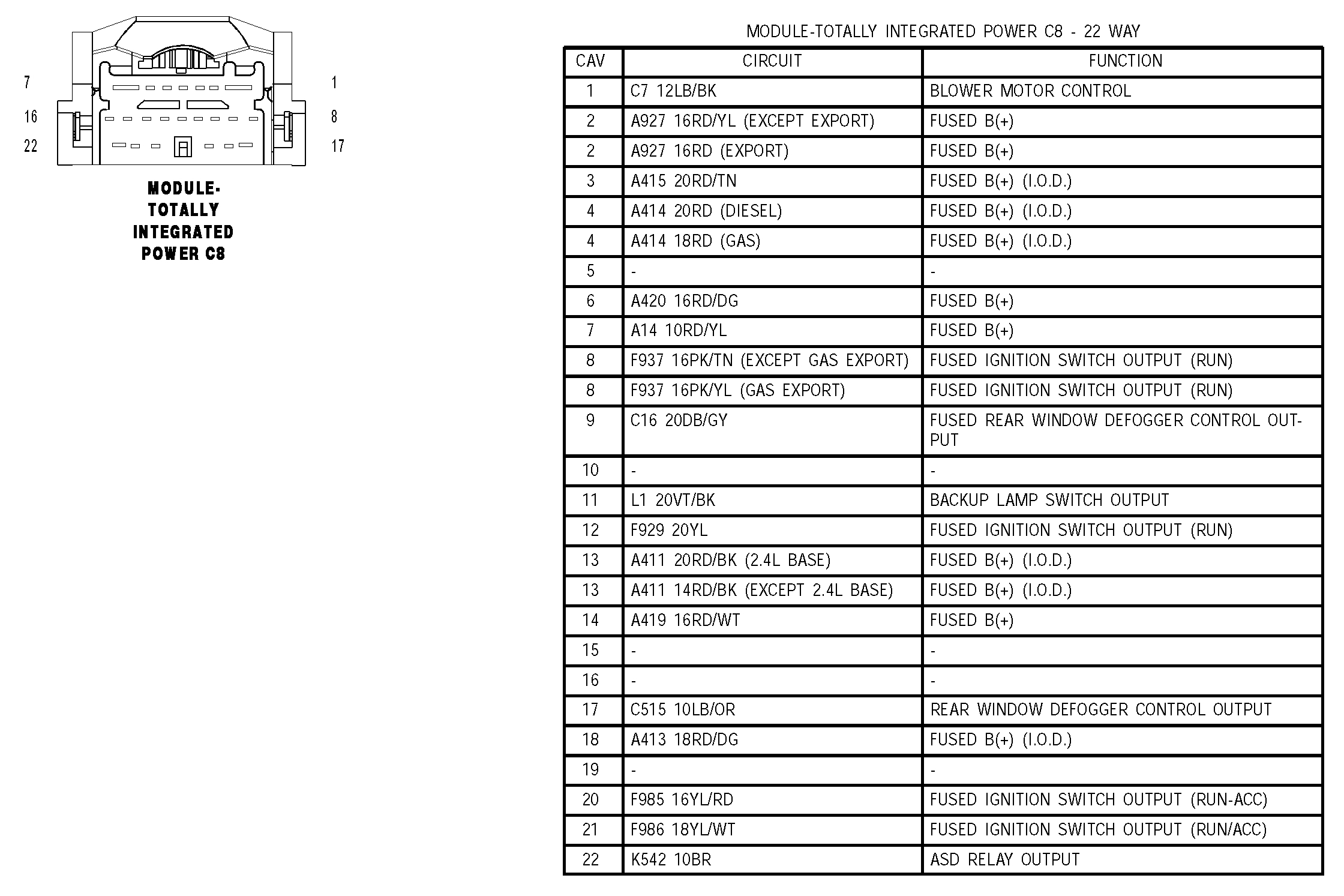
With that being said, locate the TIPM. The Totally Integrated Power Module (TIPM) is located in the left front corner of the engine compartment, just behind the air cleaner housing and the battery. Identify pin 11 and check it for corrosion or anything that can cause low power to be sent to the PCM. See picture 6
Okay, you need to locate pin connector (C11). It is a 22 pin connector. See the last picture I attached. With the battery disconnected, unfasten the connector and check its condition. Pay special attention to both the male and female ends of the plug to make sure pin 11 isn't damaged or corroded.
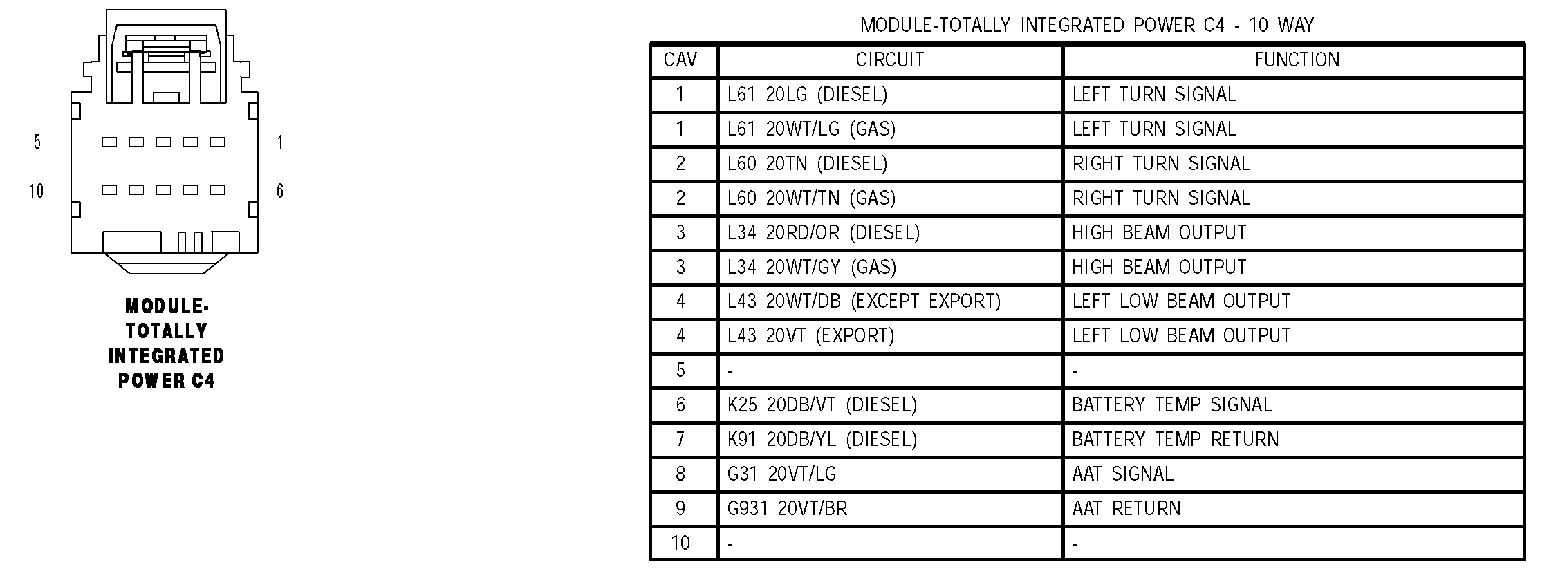
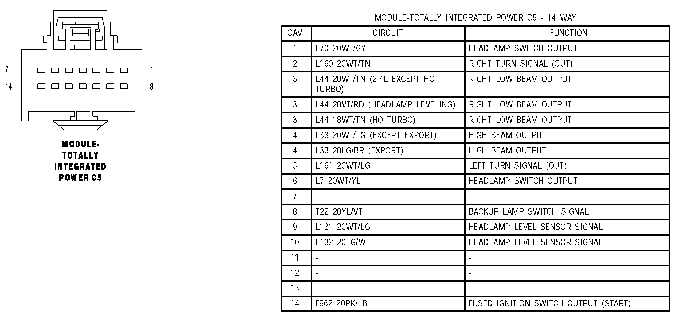
I attached the all the TIPM connector pictures for you to see. They start with pictures 7.
__________________________
If you find no problem at the TIPM, here are the diagnostics for identifying the code's cause:
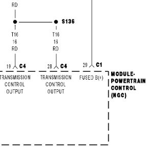
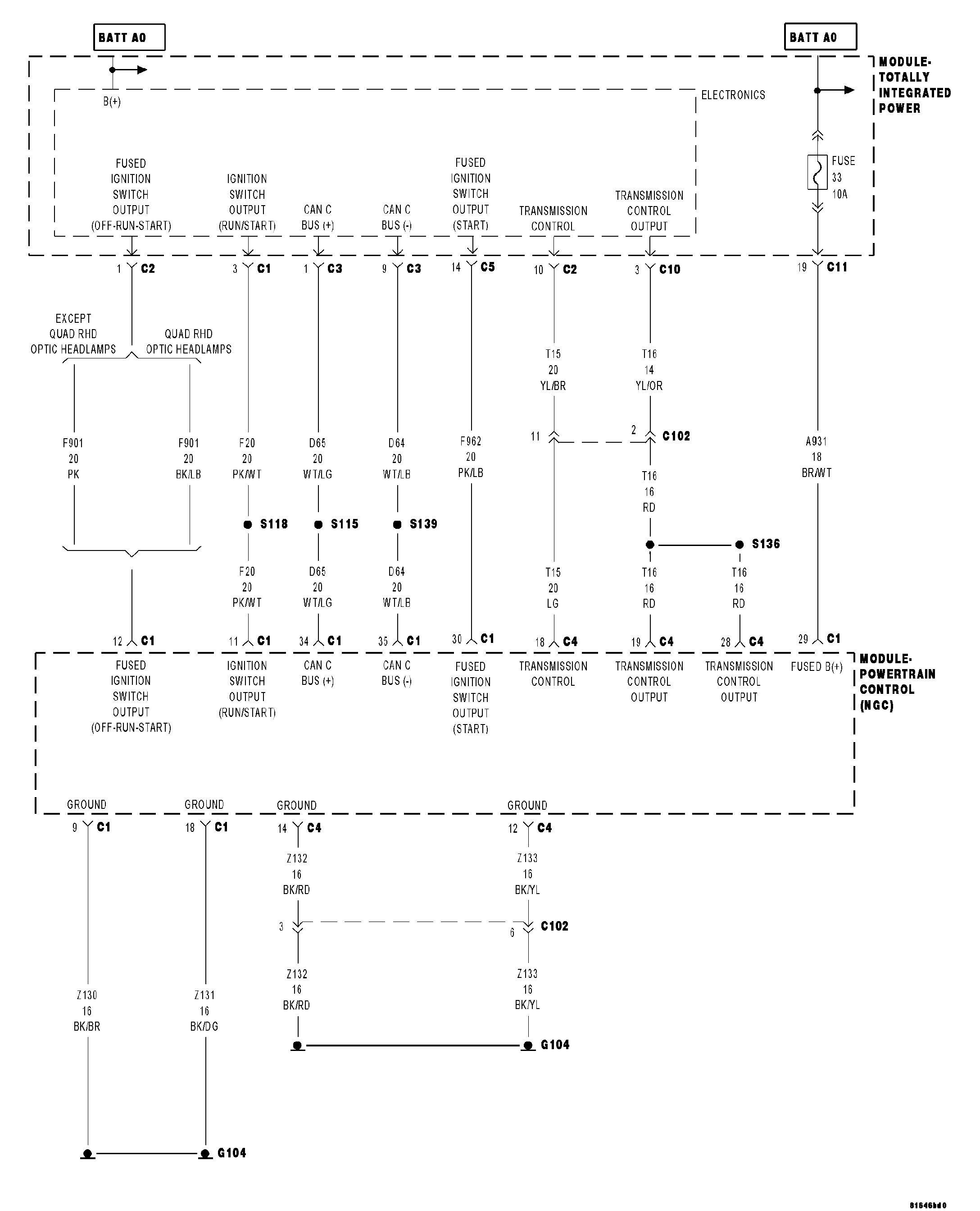
See pictures 3, 4, 5.
When Monitored:
When the ignition is turned from OFF position to RUN position and/or the ignition is turned from START position to RUN position.
Set Condition
This DTC is set when there is less than 3.0 volts present at the transmission control output circuits located in the Power-train Control Module (PCM) when the Transmission Control System request the power up of those circuits. Note: Due to the integration of the Transmission Control Module and the Power-train Control Module, both systems have their own power and ground circuits.
Possible Causes
- RELATED TIPM DTCS
- (T15) TRANSMISSION CONTROL CIRCUIT SHORT TO GROUND
- (T15) TRANSMISSION CONTROL CIRCUIT OPEN
- POWERTRAIN CONTROL MODULE
Always perform the 40/41TE Pre-Diagnostic Troubleshooting procedure before proceeding.
Theory of Operation
The Transmission Control Output circuit is used to supply power to the Transmission Solenoid/TRS Assembly and to the PCM when in normal operating mode. The purpose of the Transmission Output circuit is to allow the Transmission Control System to turn off the power to the Transmission Solenoid/TRS Assembly in event that the transmission should need to be placed into limp-in mode due to a DTC.
After a PCM reset, (ignition switch turned to the run position, or after cranking the engine) the Transmission Control System verifies that the Transmission Output circuit is open by checking for voltage on the Transmission Output circuits before the Transmission Control System request for the circuit to be powered up. The request is sent by a direct circuit control from the PCM to the TIPM. If the Transmission Control System detects less that 3.0 volts when the output is commanded on, the DTC will set. Note: Inadequate Transmission Control Output voltage can also cause DTCs P0846, or P0871, to set. This does not indicate an internal transmission or solenoid/TRS problem. Repairing the P0882 fault should also eliminate the related DTCs.
Diagnostic Test
1. CHECK IF THE DTC P0882 IS CURRENT
With the scan tool, Check the STARTS SINCE SET counter for P0882.
NOTE: This counter only applies to the last DTC set.
Is the STARTS SINCE SET counter equal to 0?
Yes >> Go To 2
No >> Go To 5
2. CHECK FOR TIPM RELATED DTCs
With the scan tool, check TIPM DTCs.
Are there any TCM TIPM DTCs present?
Yes >> Refer to Testing and perform the appropriate diagnostic procedure(s).
No >> Go To 3
imageOpen In New TabZoom/Print
3. CHECK THE (T15) TRANSMISSION CONTROL CIRCUIT FOR A SHORT TO GROUND
Turn the ignition off to the lock position.
Disconnect the PCM C4 harness connector and connect Miller tool #8815.
CAUTION: Do not probe the PCM harness connectors. Probing the PCM harness connectors will damage the PCM terminals resulting in poor terminal to pin connection. Install Miller tool #8815 to perform diagnosis.
Disconnect the TIPM C1 harness connector.
Measure the resistance between ground and the (T15) Transmission Control circuit.
Is the resistance below 5.0 ohms?
Yes >> Repair the (T15) Transmission Control circuit for a short to ground.
Perform 40/41TE VERIFICATION TEST - VER 1 See: A L L Diagnostic Trouble Codes ( DTC ) > Verification Tests > 40/41TE Transmission Verification Test
No >> Go To 4.
imageOpen In New TabZoom/Print
4. CHECK THE (T15) TRANSMISSION CONTROL CIRCUIT FOR AN OPEN
Measure the resistance of the (T15) Transmission Control circuit between the TIPM C1 harness connector and the appropriate terminal of Miller tool #8815.
Is the resistance above 5.0 ohms?
Yes >> Repair the (T15) Transmission Control circuit for an open.
Perform 40/41TE VERIFICATION TEST - VER 1 See: A L L Diagnostic Trouble Codes ( DTC ) > Verification Tests > 40/41TE Transmission Verification Test
No >> Using the schematics as a guide, check the Powertrain Control Module (PCM) terminals for corrosion, damage, or terminal push out. Pay particular attention to all power and ground circuits. If no problems are found, replace the PCM. With the scan tool, perform QUICK LEARN.
Perform 40/41TE VERIFICATION TEST - VER 1 See: A L L Diagnostic Trouble Codes ( DTC ) > Verification Tests > 40/41TE Transmission Verification Test
5. CHECK THE WIRING AND CONNECTORS
The conditions necessary to set this DTC are not present at this time.
Using the schematics as a guide, inspect the wiring and connectors specific to this circuit.
Wiggle the wires while checking for shorted and open circuits.
With the scan tool, check the DTC EVENT DATA to help identify the conditions in which the DTC was set.
Where there any problems found?
Yes >> Repair as necessary.
Perform 40/41TE VERIFICATION TEST - VER 1 See: A L L Diagnostic Trouble Codes ( DTC ) > Verification Tests > 40/41TE Transmission Verification Test
No >> Test Complete.
_________________________________________________
I realize this isn't an easy one to fix. However, the TIPM is my first suspect. All of the pins are on the underside of the fuse or power distribution box. That is where they will plug into the TIPM.
Here are a few general links to help with checking wiring, power supplies:
https://www.2carpros.com/articles/how-to-use-a-test-light-circuit-tester
https://www.2carpros.com/articles/how-to-use-a-voltmeter
https://www.2carpros.com/articles/how-to-check-wiring
_____________________________________
Let me know if any of this helps or if you have other questions.
Take care,
Joe
Images (Click to enlarge)
Dec 14, 2018 at 7:31 PM