Hi,
Okay. Make sure to check the pistons for damage once the head is removed. Here are the directions for removal and replacement of the head. The attached pics correlate with the directions.
___________________________________________________
1997 Honda Accord DX Sedan L4-2156cc 2.2L SOHC MFI
Removal
Vehicle Engine, Cooling and Exhaust Engine Cylinder Head Assembly Service and Repair Procedures Removal and Installation Removal
REMOVAL
WARNING: Make sure jacks and safety stands are placed properly and hoist brackets are attached to correct position on the engine.
CAUTION:
Use fender covers to avoid damaging painted surfaces.
Unplug the wiring connectors carefully while holding the connector portion to avoid damage.
To avoid damaging the cylinder head, wait unto the engine coolant temperature drops below 100°F (38°C) before loosening the retaining bolts.
NOTE:
Engine removal is not required for this procedure.
Unspecified items are common with both engines.
Mark all wiring and hoses to avoid misconnection. Also, be sure that they do not contact other wiring or hoses, or interfere with other parts.
Inspect the timing belt before removing the cylinder head.
Turn the crankshaft pulley so that the No. 1 piston is at top dead center.
The original radio has a coded then protection circuit. Be sure to get the customer's code number before
- disconnecting the battery.
- removing the No. 39 (7.5 A) fuse from the under hood fuse/relay box.
- removing radio.
After service, reconnect power to the radio and turn it on. When the word "CODE" is displayed, enter the customer's 5-digit code to restore radio operation.
1. Disconnect the battery negative terminal first, then the positive terminal.
2. Drain the engine coolant.
- Remove the radiator cap to speed draining.
Pic 1
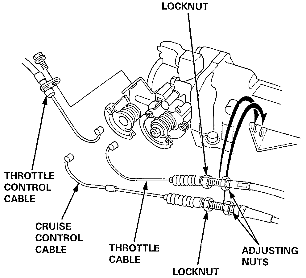
3. Remove the throttle cable, throttle control cable (Automatic Transmission [A/T]) and cruise control cable.
NOTE:
Take care not to bend the cable when removing it. Always replace any kinked cable with a new one.
Adjust the throttle cable, throttle control cable and cruise control cable when installing.
Pic 2
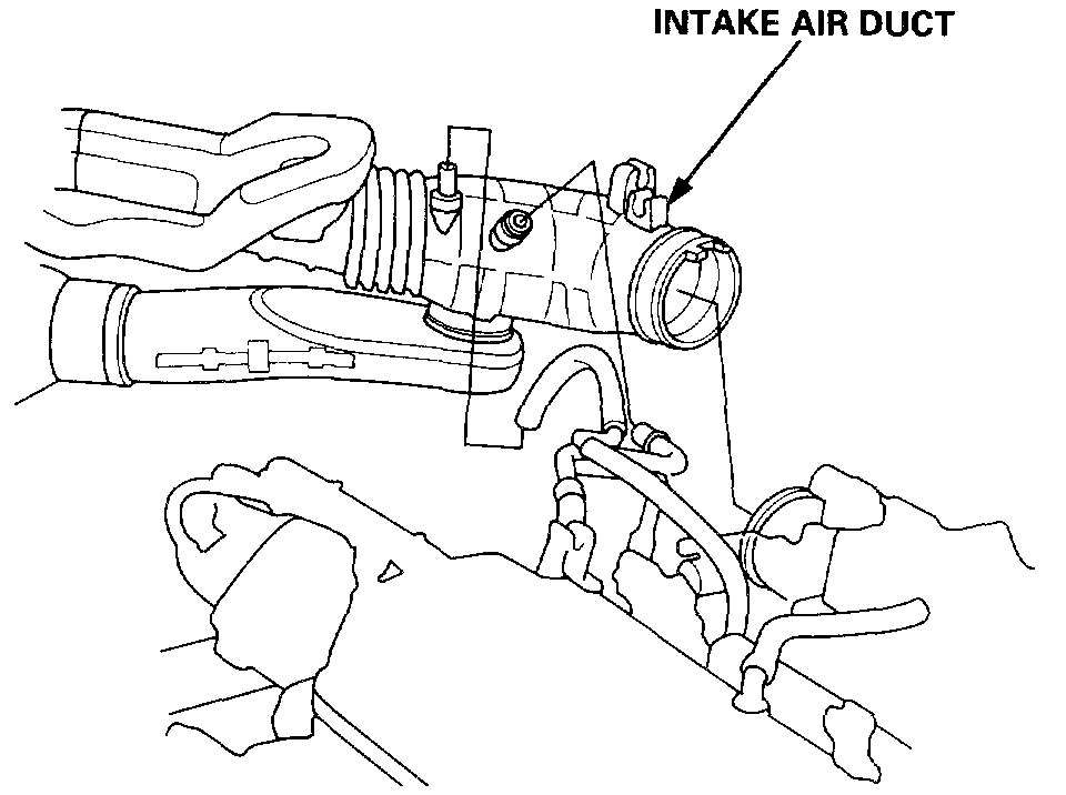
4. Remove the intake air duct.
Pic 3
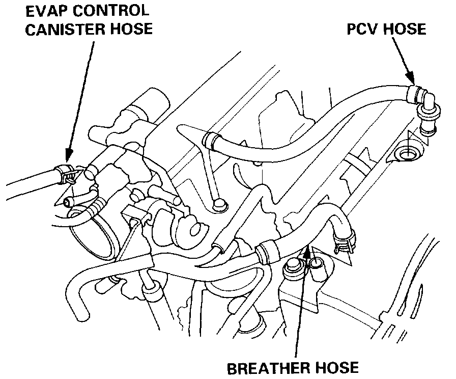
5. Remove the breather hose, positive crankcase ventilation (PCV) hose and Evaporative Emission (EVAP) control canister hone.
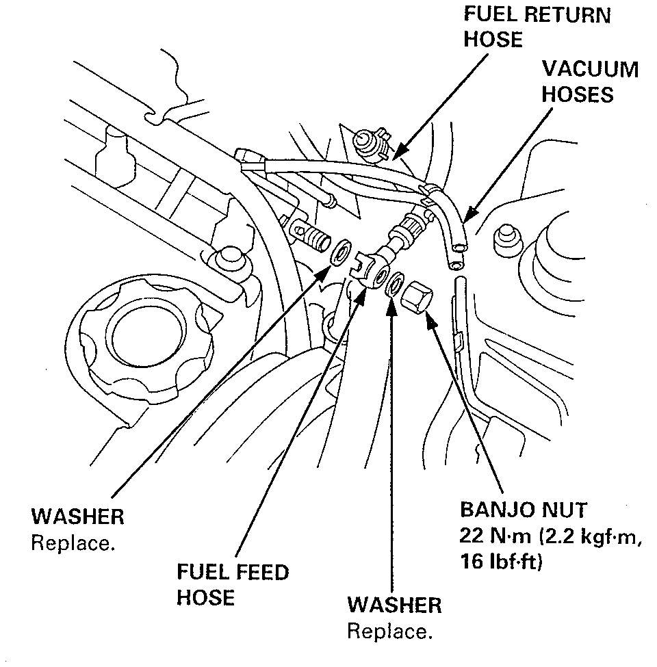
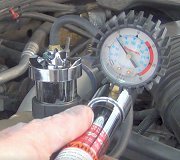
6. Relieve fuel pressure.
Do not smoke while working on fuel system, keep open flame or spark away from work area. Drain fuel only into an approved container.
Pic 4
7. Remove the fuel feed hose, fuel return hose and vacuum hoses.
8. Remove the brake booster vacuum hose and vacuum hoses.
Pic 5
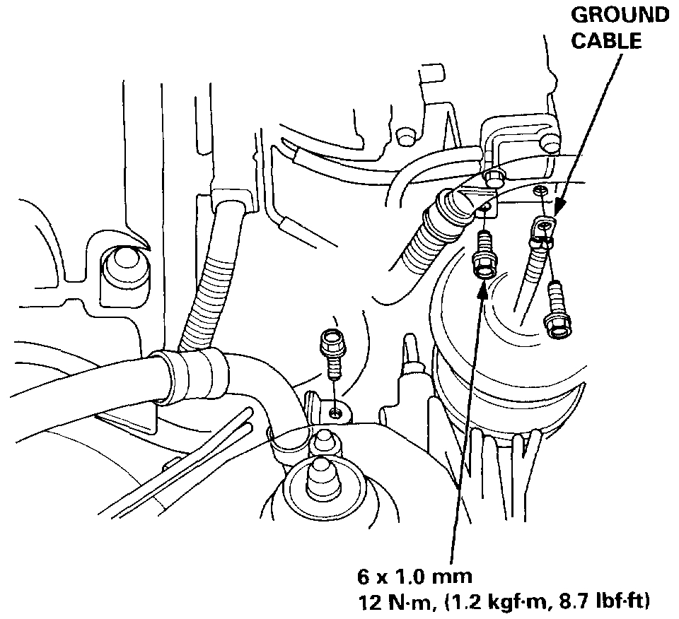
9. Remove the Power Steering (P/S) hose clamp, wire harness clamp and engine ground cable.
10. Remove the battery cable and alternator connector. Refer to Starting and Charging.
11. Remove the P/S pump belt and P/S pump. Refer to Steering and Suspension.
12. Remove the alternator belt. Refer to Starting and Charging.
Pic 6
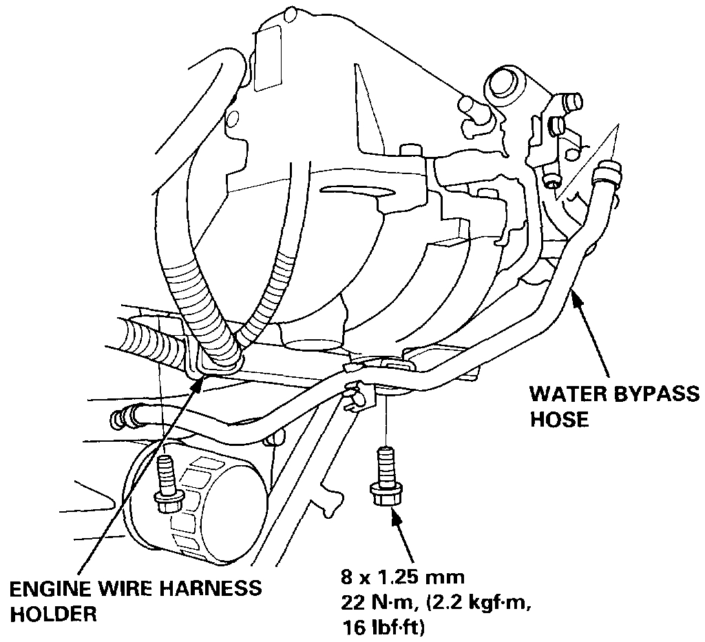
13. Remove the engine wire harness holder and water bypass hose.
14. Remove the engine wire harness connectors and wire harness clamps from the cylinder head and the intake manifold.
Four injector connectors
Intake Air Temperature (IAT) sensor connector
Idle Air Control (IAC) valve connector
Throttle position sensor connector
Manifold Absolute Pressure (MAP) sensor connector
Primary Heated Oxygen Sensor (Primary H02S) connector
Engine Coolant Temperature (ECT) sensor connector
ECT switch connector
ECT gauge sending unit connector
Exhaust Gas Re-circulation (EGR) valve lift sensor connector
Camshaft Position (CYP) sensor connector
Ignition coil connector
15. Remove the spark plug caps and distributor from the cylinder head.
Pic 7
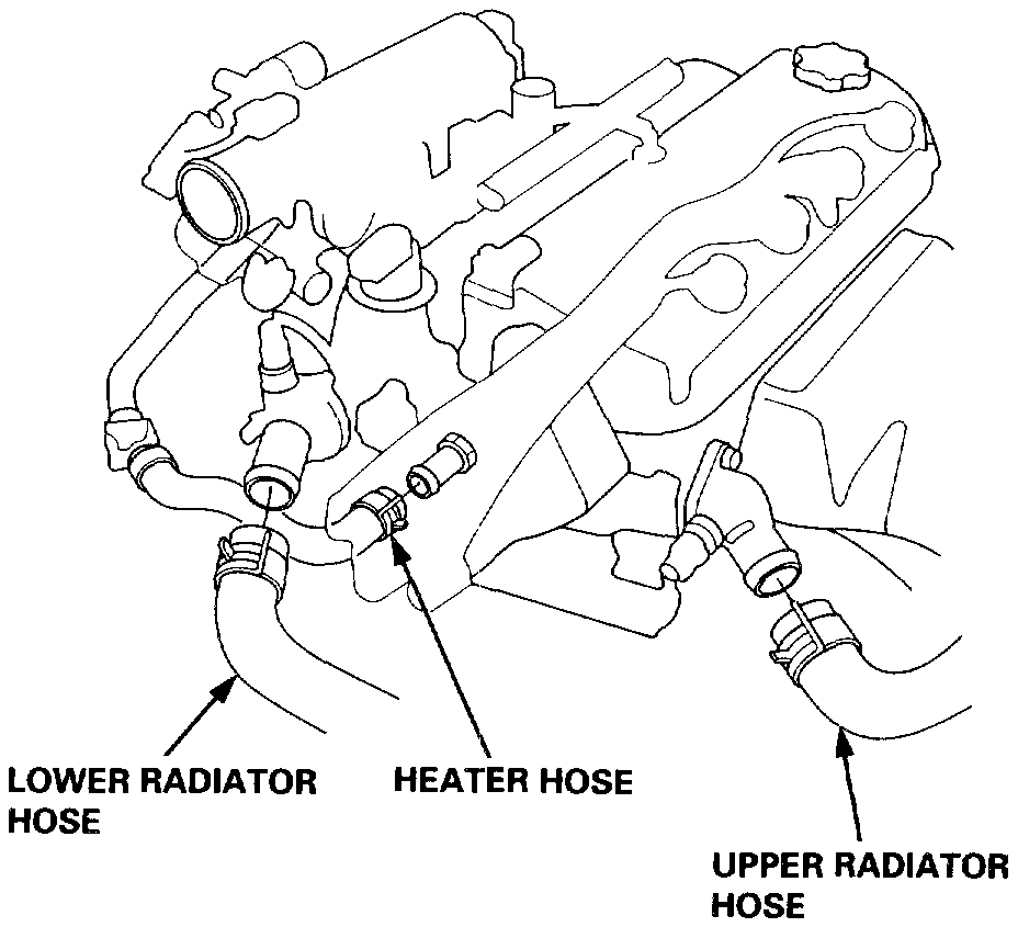
16. Remove the upper and lower radiator hoses and heater hose.
Pic 8
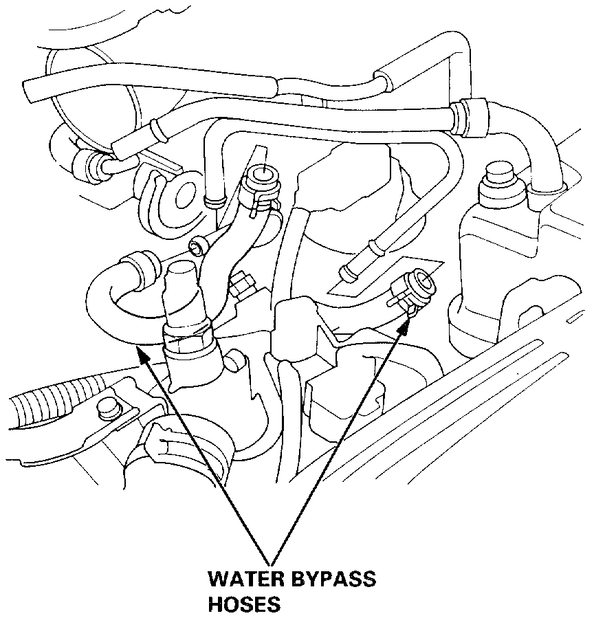
17. Remove the water bypass hoses.
18. Remove the side engine mount.
NOTE:
Use the jack to support the engine before the side engine mount is removed.
Make sure to place a cushion between the oil pan and the jack.
Pic 9
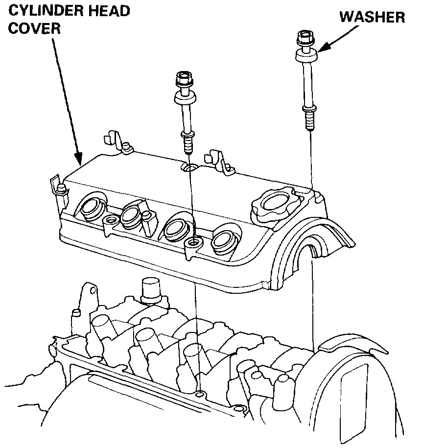
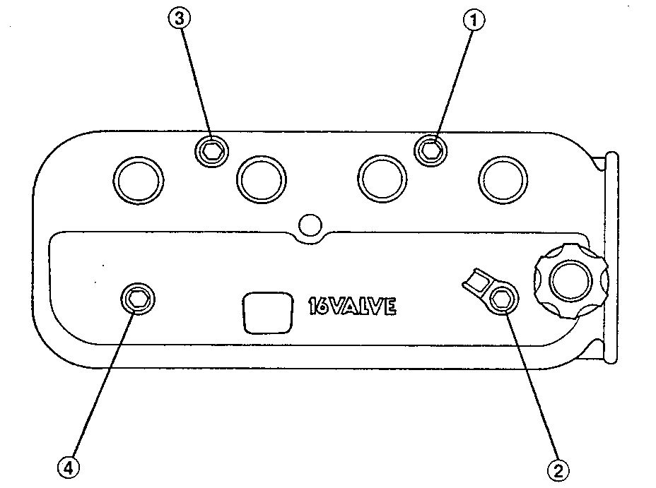
19. Remove the cylinder head cover.
20. Remove the timing belt.
Pic 10
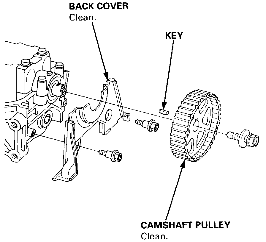
21. Remove the camshaft pulley and back cover.
22. Remove the splash shield.
Pic 11
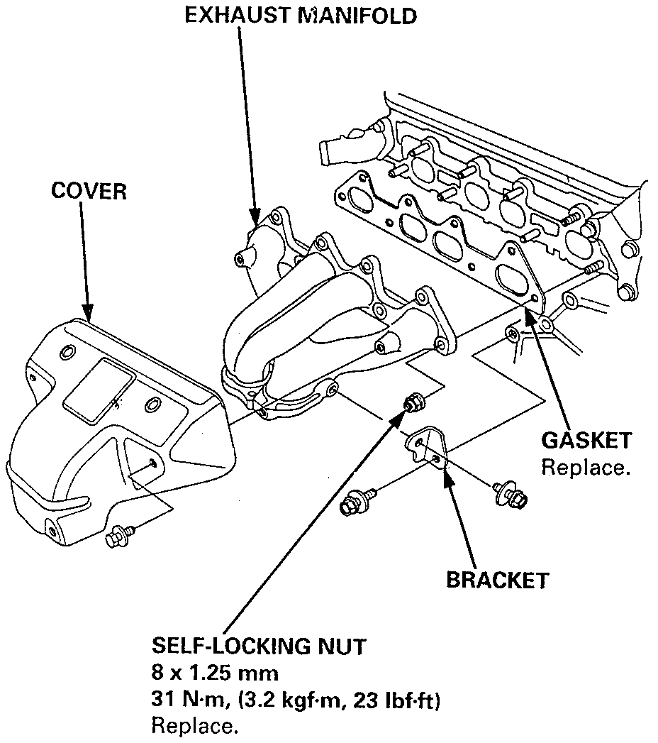
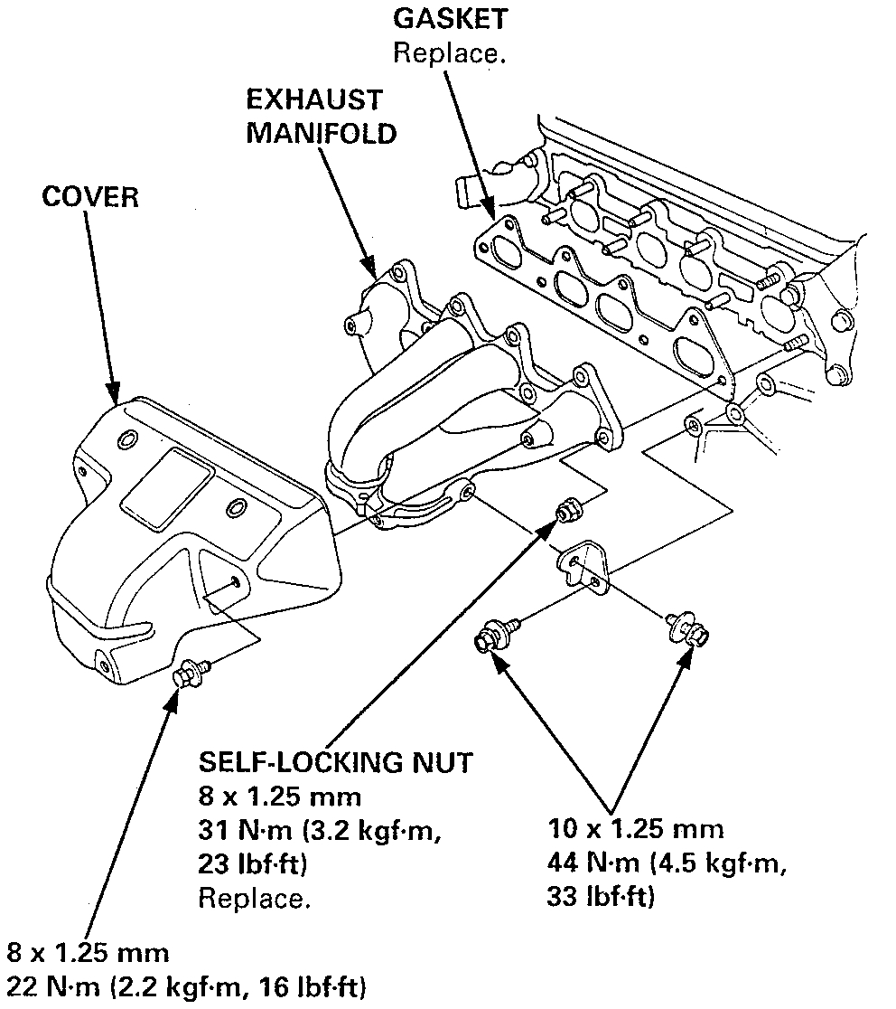
23. Remove the exhaust manifold.
Pic 12
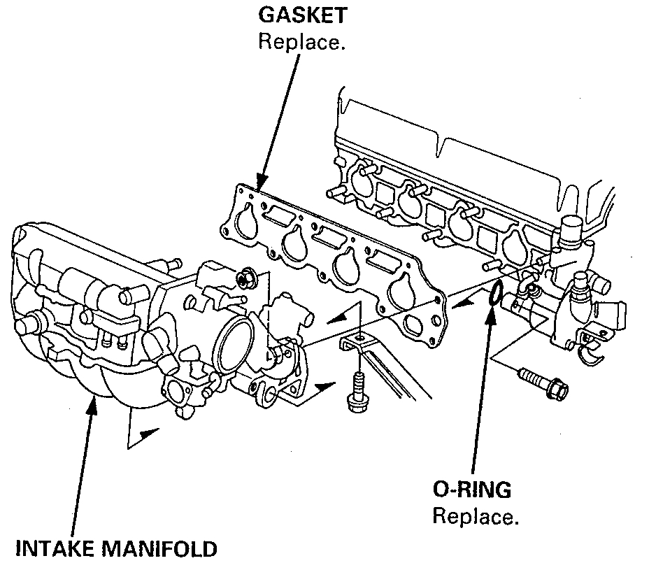
24. Remove the intake manifold.
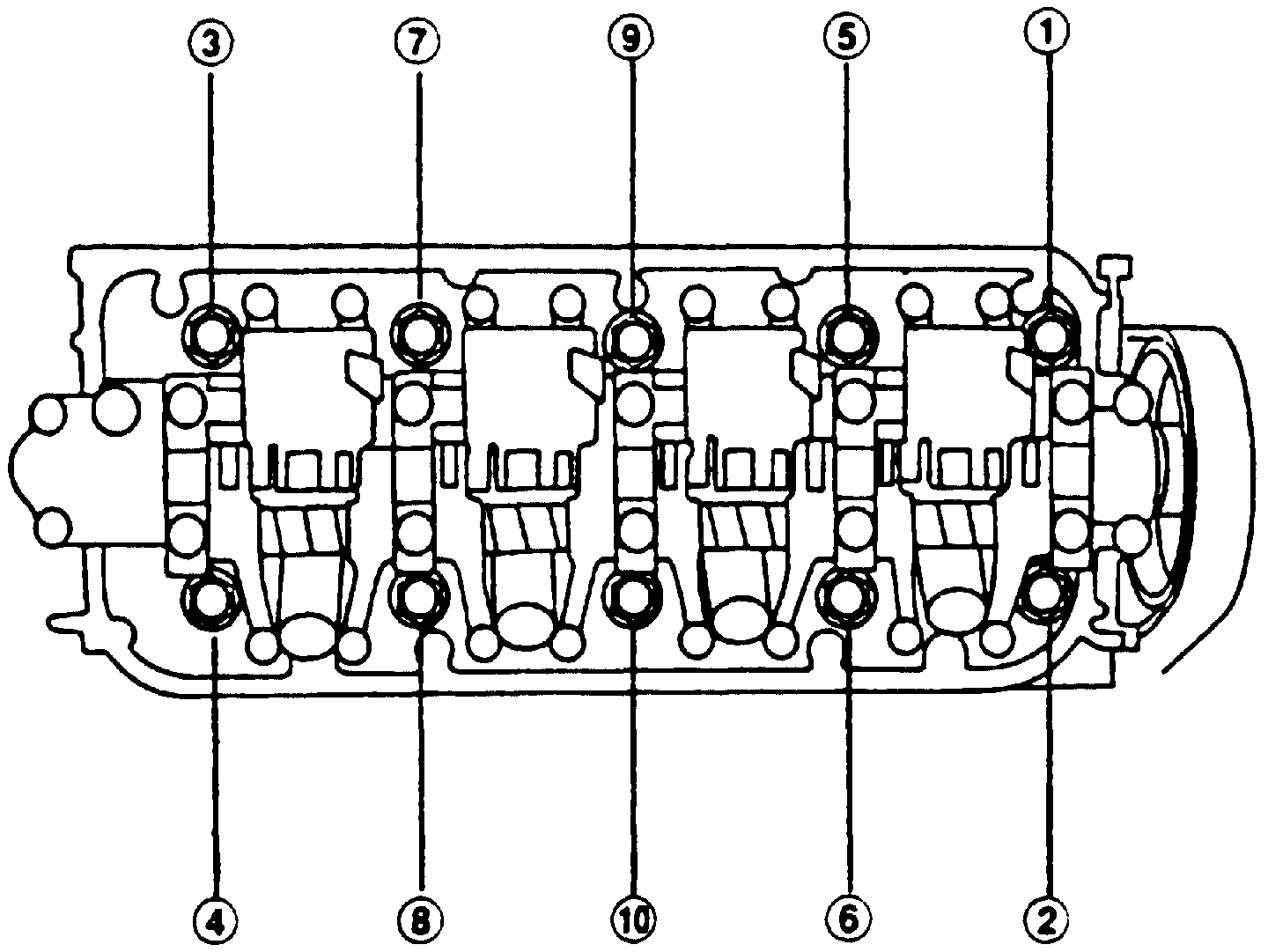
Fig. 11 Cylinder Head Bolt Loosening Sequence
pic 13
25. Remove the cylinder head bolts, then remove the cylinder head.
CAUTION: To prevent warpage, unscrew the bolts in sequence 1/3 turn at a time; repeat the sequence until all bolts are loosened.
_____________________________________________________
1997 Honda Accord DX Sedan L4-2156cc 2.2L SOHC MFI
Installation
Vehicle Engine, Cooling and Exhaust Engine Cylinder Head Assembly Service and Repair Procedures Removal and Installation Installation
INSTALLATION
NOTE:
Install the cylinder head in the reverse order of removal:
Always use a new head gasket.
Cylinder head and cylinder block surface must be clean.
"UP" mark on camshaft pulley should be at the top.
Turn the crankshaft so the No. 1 piston is at Top Dead Center (TDC).
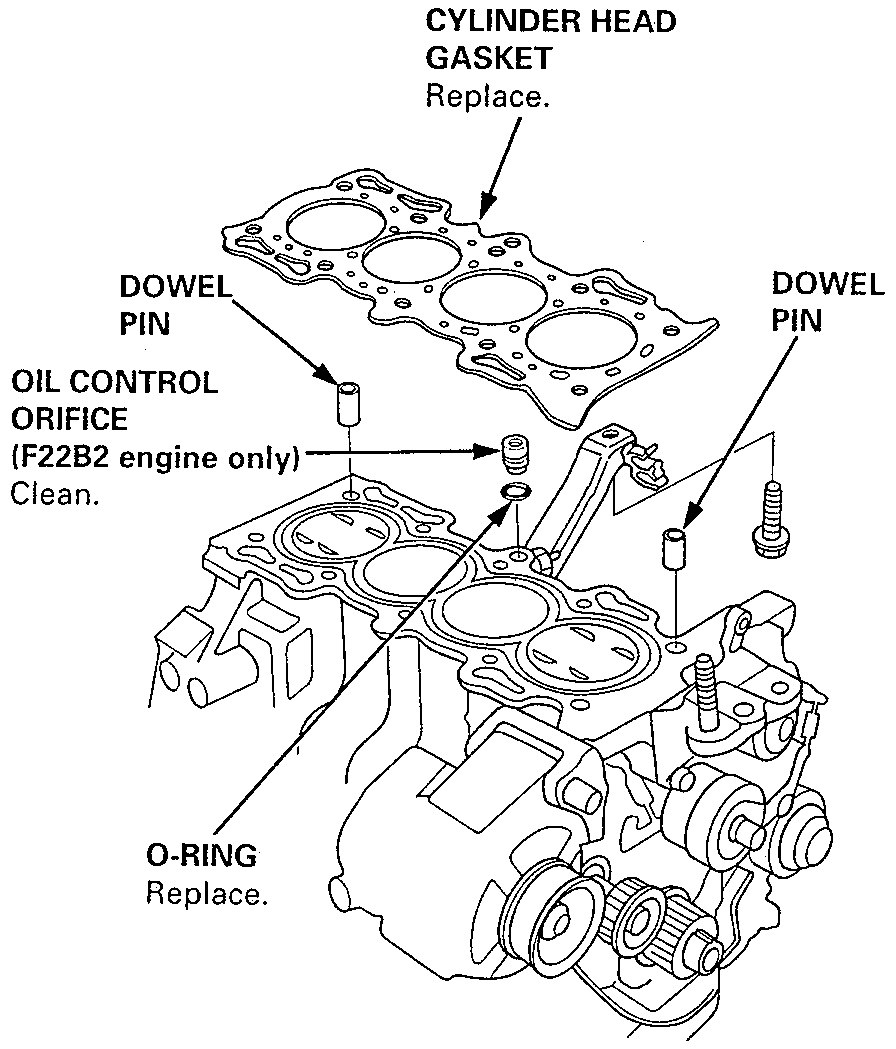
Clean the oil control orifice before installing.
Do not use the upper cover and lower cover for storing removed items.
Clean the upper cover and lower cover before installation.
1. Cylinder head dowel pins must be aligned.
Pic 14
2. Install the oil control orifice.
3. Position the camshaft correctly.
Pic 15
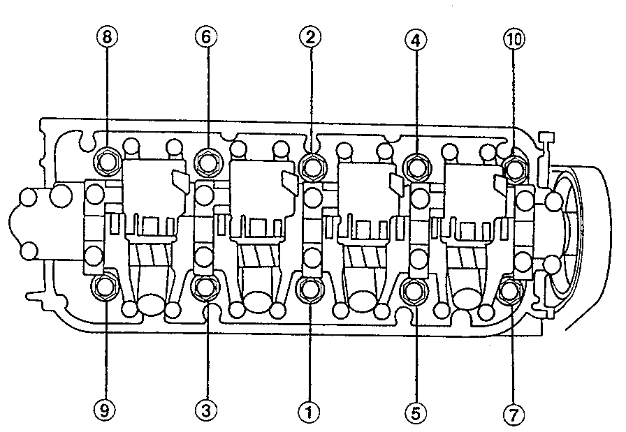
4. Tighten the cylinder head bolts sequentially in three steps.
1st step torque: 39 Nm (29 ft. Lbs.)
2nd step torque: 69 Nm (51 ft. Lbs.)
3rd step torque: 98.1 Nm (72.3 ft. Lbs.)
NOTE:
We recommend using a beam-type torque wrench. When using a preset-type torque wrench, be sure to tighten slowly and not to over-tighten.
- If a bolt makes any noise while you are torquing it, loosen the bolt, and re-tighten it from the 1st step.
Pic 16
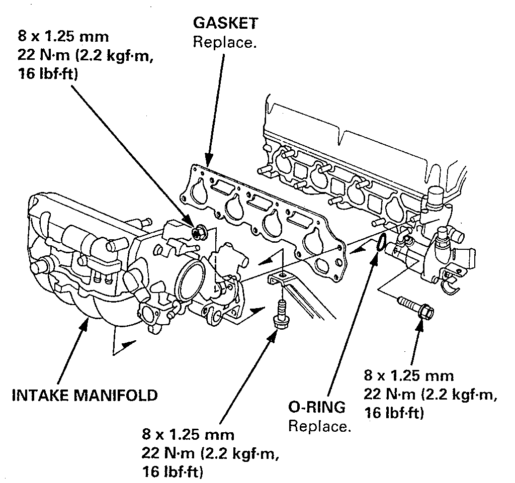
5. Install the intake manifold and tighten the nuts in a crisscross pattern in 2 or 3 steps, beginning with the inner nuts.
Always use a new intake manifold gasket.
6. Install the exhaust manifold and tighten the nuts in a crisscross pattern in 2 or 3 steps, beginning with the inner nut.
Always use a new exhaust manifold gasket.
Pic 17
7. Install the exhaust manifold bracket, then install the exhaust pipe A and the bracket, and then install the cover.
8. Install the timing belt.
9. Adjust the valve clearance.
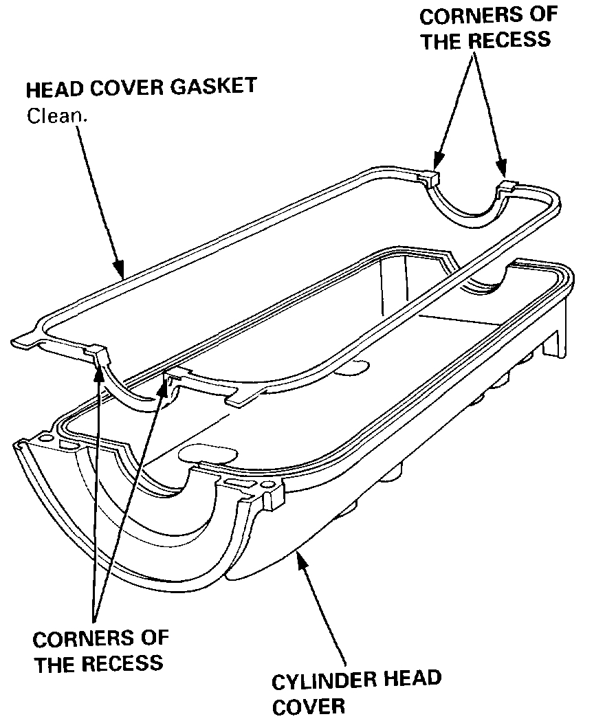
Pic 18
10. Install the head cover gasket in the groove of the cylinder head cover. Seat the recesses for the camshaft first, then work it into the groove around the outside edges.
NOTE:
Before installing the head cover gasket, thoroughly clean the seal and the groove.
When installing, make sure the head cover gasket is seated securely in the corners of the recesses with no gap.
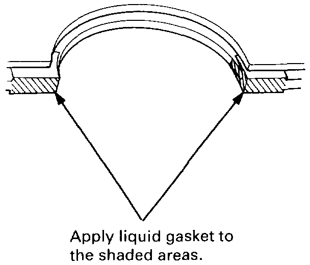
Pic 19
11. Apply liquid gasket to the head cover gasket at the four corners of the recesses.
NOTE:
Use liquid gasket, Part No. 08718-0001, or equivalent.
Check that the mating surfaces are clean and dry before applying liquid gasket.
Do not install the parts if 5 minutes or more have elapsed since applying liquid gasket. Instead, reapply liquid gasket after removing old residue.
After assembly, wait at least 20 minutes before filling the engine with oil.
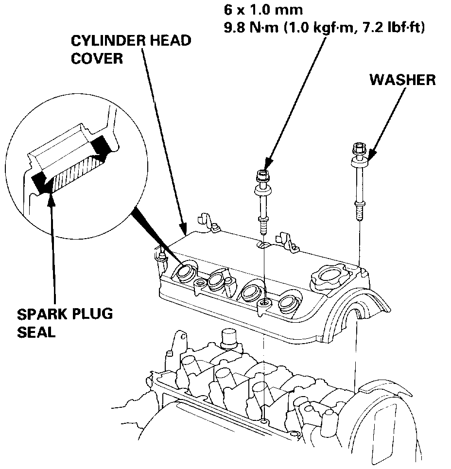
Pic 20
12. When installing the cylinder head cover, hold the head cover gasket in the groove by placing your fingers on the camshaft contacting surfaces (top of the semicircles).
Once the cylinder head cover is on the cylinder head, slide the cover slightly back and forth to seat the head cover gasket.
NOTE:
Before installing the cylinder head cover, clean the cylinder head contacting surfaces with a shop towel.
Do not touch the parts where liquid gasket was applied.
Replace the washer when damaged or deteriorated.
Pic 21
13. Tighten the nuts in 2 or 3 steps. In the final step, tighten all nuts, in sequence, to 9.8 Nm (7.2 ft. Lbs.).
NOTE: After assembly, wait at least 20 minutes before filling the engine with oil.
14. After installation, check that all tubes, hoses and connectors are installed correctly.
________________________________
I hope this helps. Let me know if you need anything else or have questions.
Take care,
Joe
Images (Click to make bigger)
Wednesday, July 22nd, 2020 AT 4:41 PM