Hi and thanks for using 2CarPros.com.
If the lean is near the pump, either there is a leaking hose or the weep hole on the pump is leaking. Take a look through this link. It discusses how to check and repair coolant leaks. It does discuss the weep hole I mentioned.
https://www.2carpros.com/articles/car-is-leaking-coolant
Here is a link that shows how to pressure test the cooling system. You will need to rent the tool, unless you have one.
https://www.2carpros.com/articles/radiator-pressure-test
_______________________________
As far as the distributor cap, there is no coolant in it. If there is coolant there, check heater hoses around it.
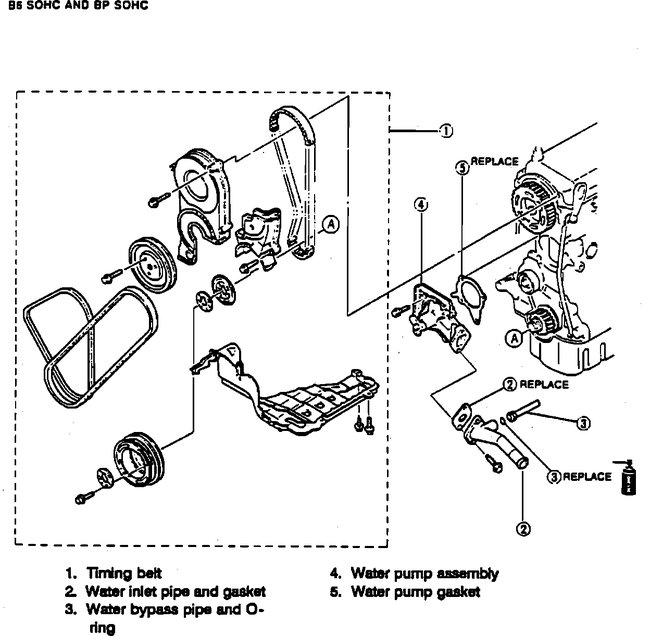
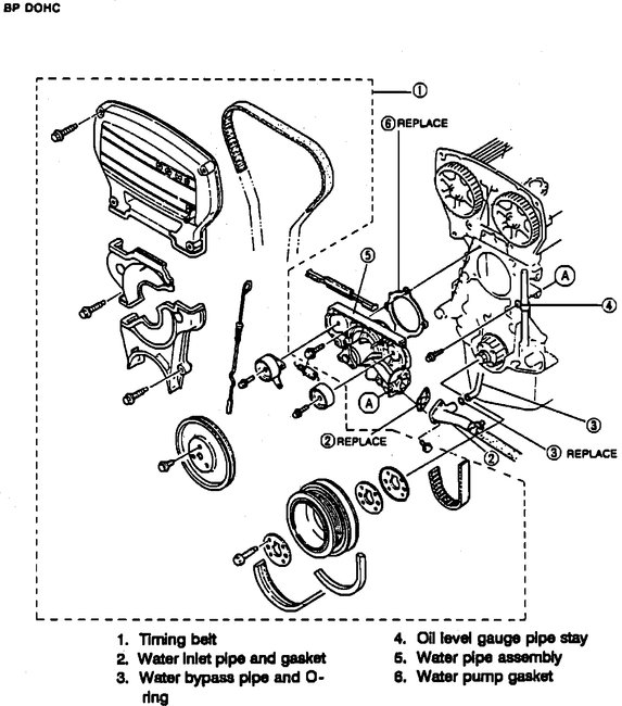
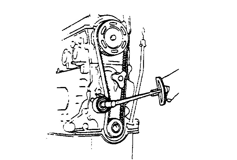
If you find the leak is the water pump, here are the directions for replacement. The first two pictures correlate with these directions.
_________________
109 Water Pump Replacement. SOHC Engine (pic 1)
Fig. 110 Water Pump Replacement. DOHC Engine (pic 2)
1. Remove timing belt, refer to TIMING BELT.
2. Remove water inlet and bypass pipes.
3. Remove water pump mounting bolts, then water pump, Figs. 109 and 110.
4. Reverse procedure to install.
____________________
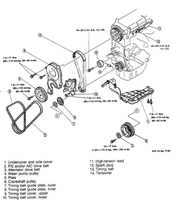
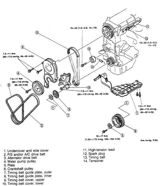
To replace the water pump requires removal of the timing belt. Here are the directions for both types of engines. (pictures 3-16)
SOHC (single overhead cam)
TIMING BELT REMOVAL AND INSTALLATION
imageOpen In New TabZoom/Print
TIMING BELT
1. Disconnect the negative battery cable.
2. Lift up the vehicle
REMOVAL
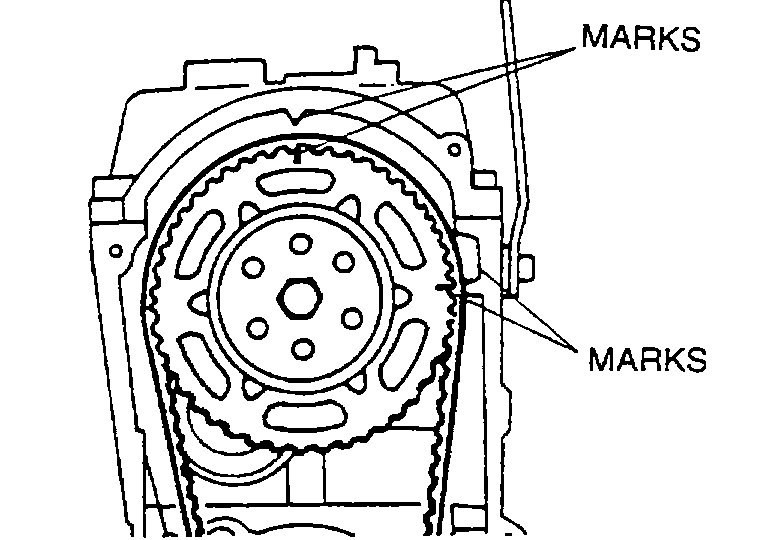
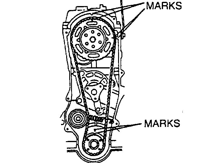
1. Turn the crankshaft and align the marks.
NOTE:
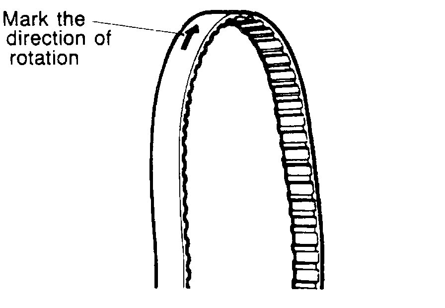
Mark the timing belt rotation for proper reinstallation.
INSPECTION
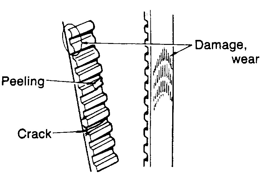
Inspect the following parts:
1. Timing belt
2. Timing belt tensioner and spring
3. Timing belt pulley
4. Camshaft pulley
INSTALLATION
Tensioner, tensioner spring
1. Install the tensioner and the tensioner spring.
2. Temporarily secure the tensioner with the spring fully extended.
Timing belt
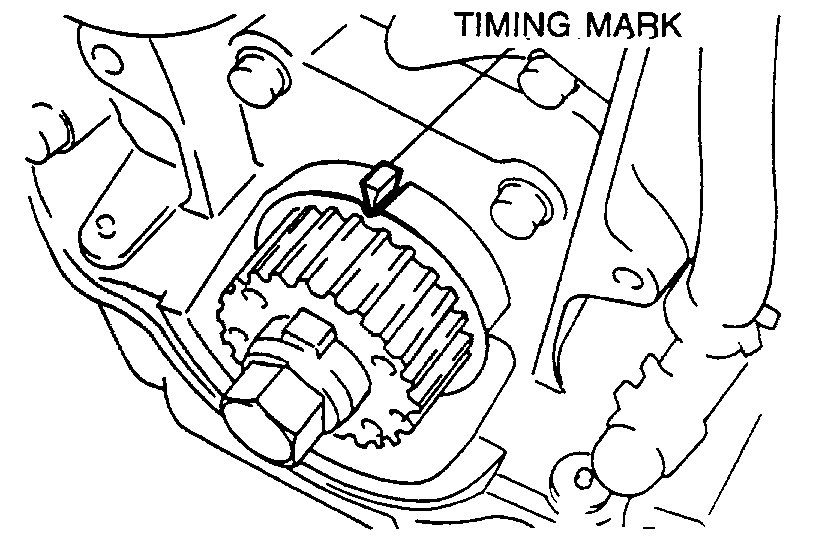
1. Verify that the timing belt pulley mark is aligned with the timing mark.
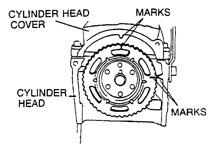
2. Verify that the camshaft pulley marks are aligned with the cylinder head cover mark.
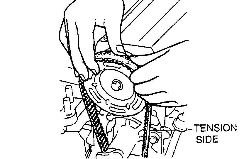
3. Install the timing belt so that there is no looseness at the tension side.
CAUTION:
Do not turn the crankshaft counterclockwise.
4. Turn the crankshaft two turns clockwise, and align the timing belt pulley mark with the timing mark.
5. Verify that the camshaft pulley marks are aligned with the cylinder head cover mark.If not aligned, remove the timing belt and repeat from tensioner installation.
6. Loosen the tensioner lock bolt to apply tension to the timing belt.
CAUTION:
Be sure not to apply tension other than that of the tensioner spring.
7. Tighten the tensioner lock bolt.
Tightening torque:
19-25 N-m (1.9-2.6 m-kg, 14-19 ft-lb)
8. Turn the crankshaft 2 turns clockwise and verify that the marks are correctly aligned.
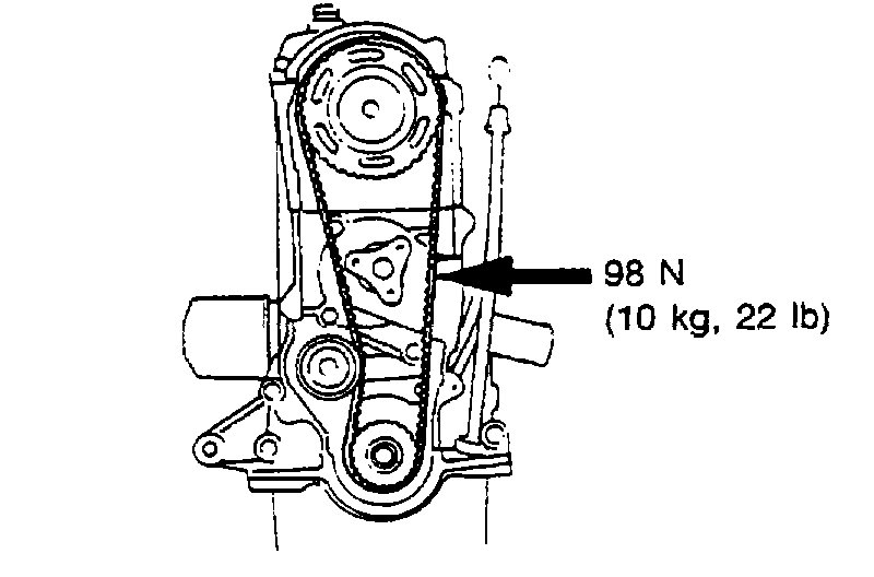
9. Check the timing belt deflection by applying moderate pressure (98 N, 10 kg, 22 lb) midway between the crankshaft pulley and the camshaft pulley.If the timing belt deflection is not correct, temporarily secure tensioner lock bolt so the spring is fully extended and repeat steps 4-8 above or replace the tensioner spring.
Deflection:
11.0-13.O mm (0.43-0.51 in) at 98 N (10 kg, 22 lb)
Spark plug
1. Apply antisize compound or molybdenum-based lubricant to the spark plug threads.
2. Install the spark plugs.
Tightening torque:
15-23 N-m (1.5-2.3 M-kg, 11-17 ft-lb)
Timing belt guide plate, inner
CAUTION:
Make sure the timing belt inner guide plate is installed in the proper direction.
1. Install the timing belt inner guide plate.
Steps After Installation
1. Connect the negative battery cable.
2. Start the engine and check the ignition timing.
__________________________
Here are the directions for the DOHC engine (all remaining pictures)
TIMING BELT
1. Disassemble in the order shown in the figure, referring to Disassembly Note.
2. Assemble in the reverse order of disassembly, referring to Assembly Note.
Timing Belt
Disassembly Note
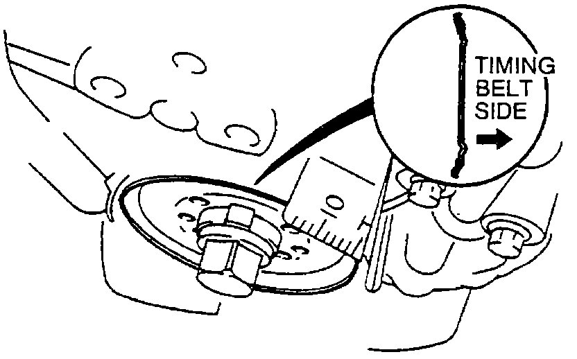
Crankshaft pulley and plate
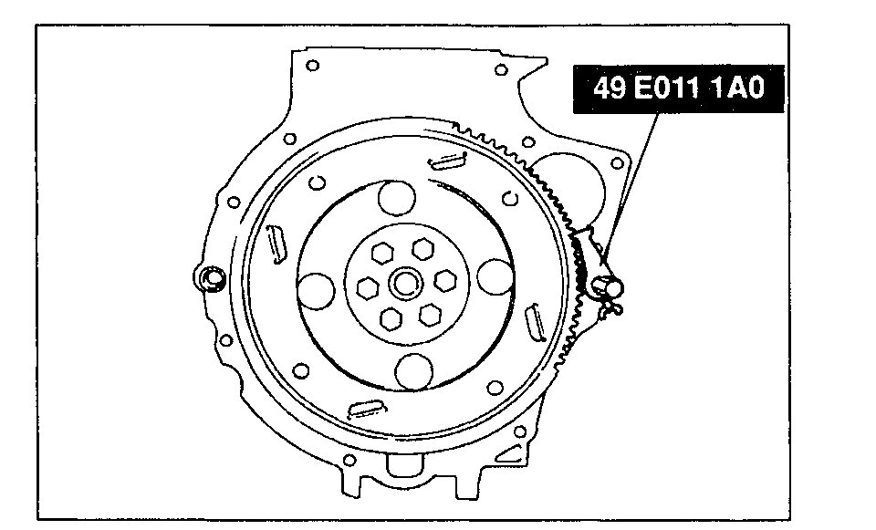
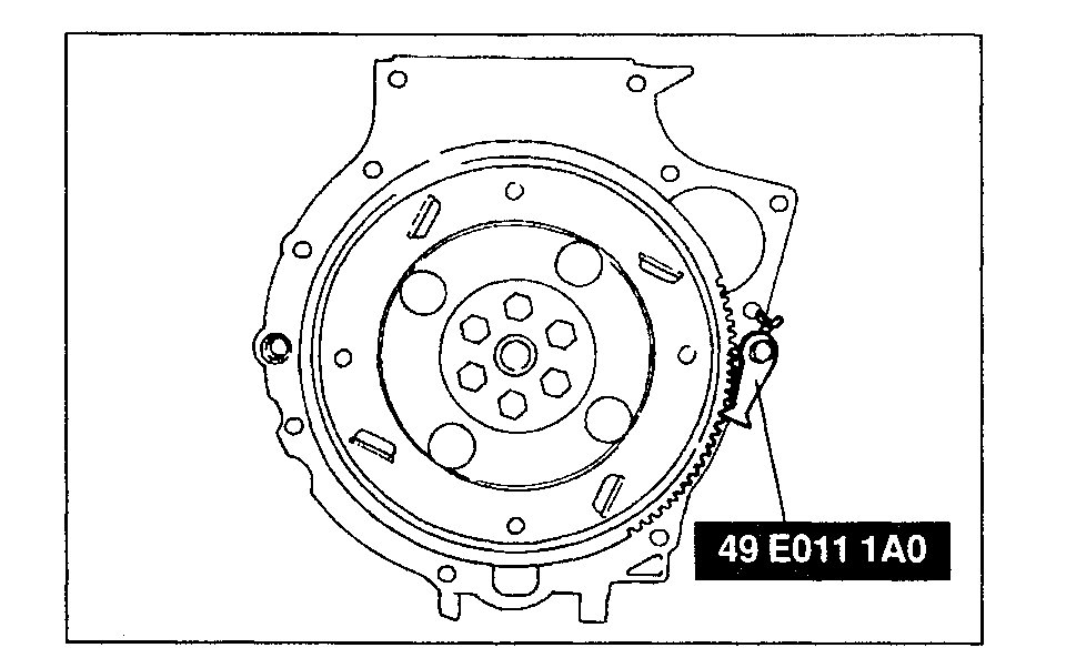
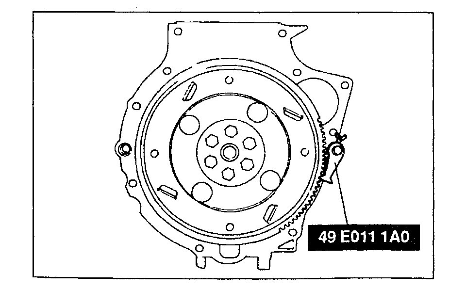
1. Hold the flywheel (MTX) or drive plate (ATX) by using the SST.
2. Remove the crankshaft pulley and plate.
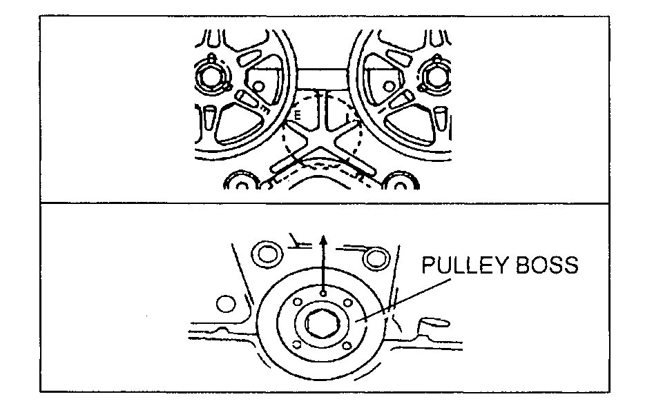
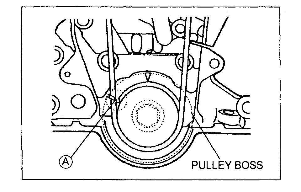
Pulley boss
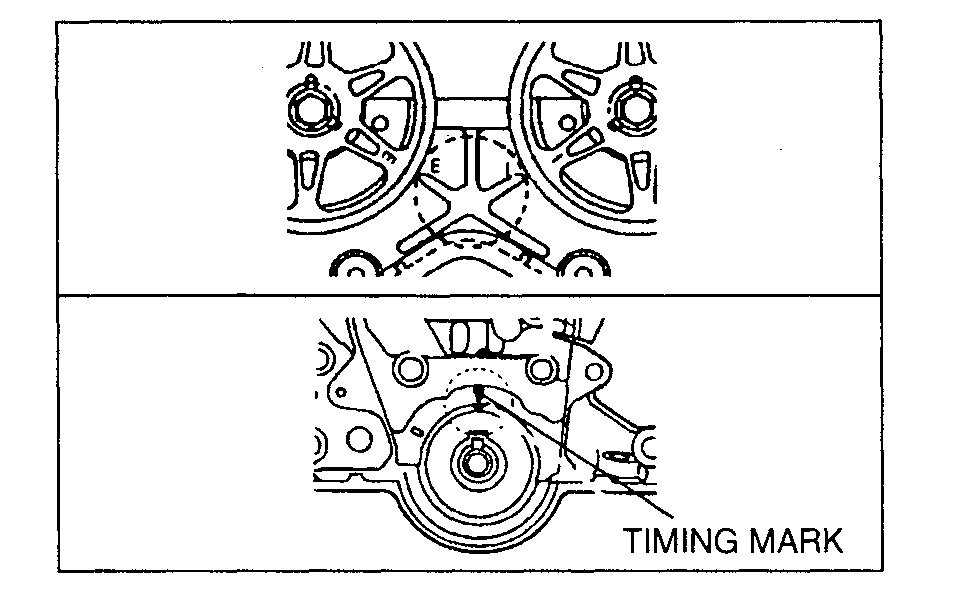
1. Turn the crankshaft clockwise and align the timing marks of the pulleys.
Note
For the crankshaft side, face the locating pin on the pulley boss straight up.
2. Hold the flywheel (MTX) or drive plate (ATX) by using the SST.
3. Remove the pulley boss.
Timing belt
Caution
The following will damage the belt and shorten its life; Forcefully twisting it, turning it inside out, or allowing oil or grease on it.
1. Mark the timing belt rotation on the belt for proper reinstallation.
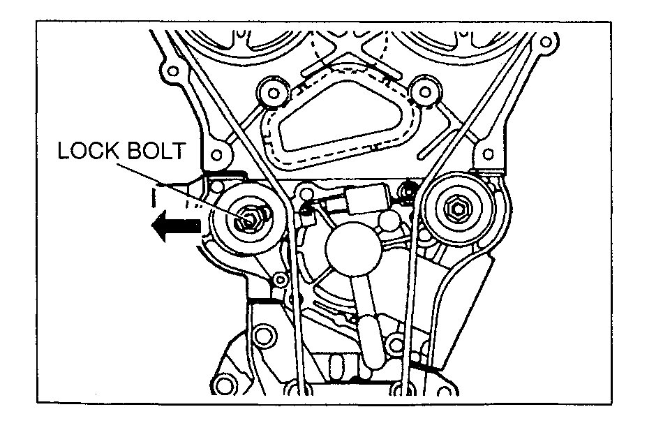
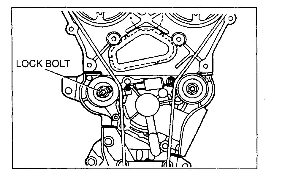
2. Loosen the tensioner lock bolt.
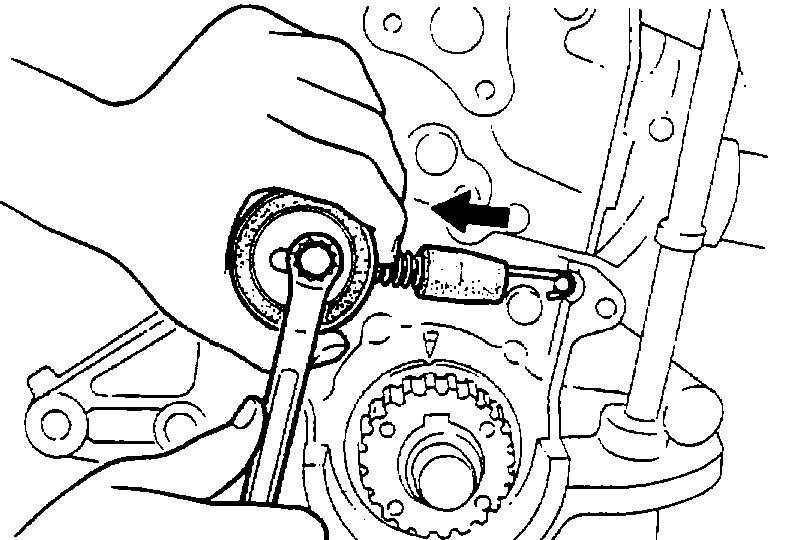
3. Push the tensioner in the direction of the arrow and hand tighten the lock bolt.
4. Remove the timing belt.
Assembly Note
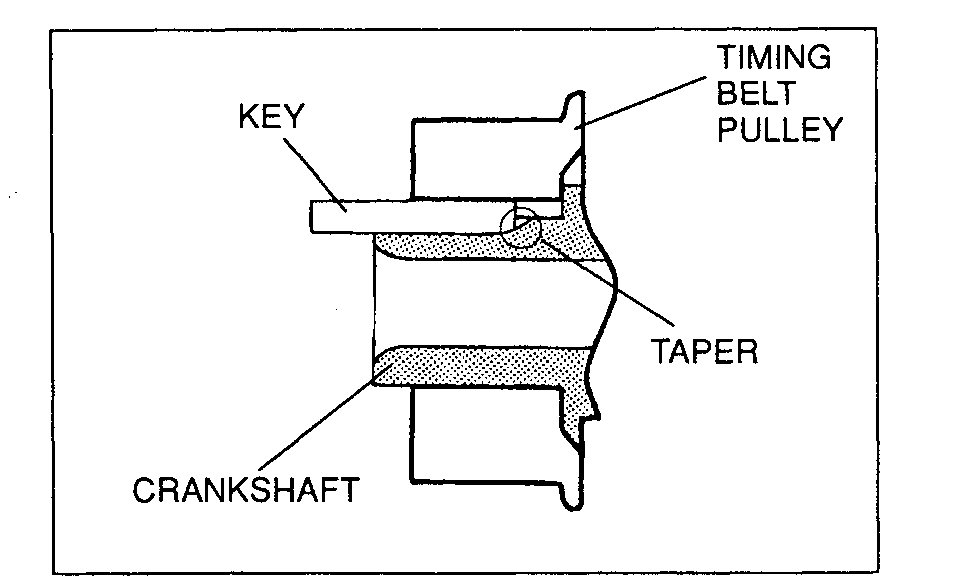
Timing belt pulley and key
Insert the key into the timing belt pulley, facing the tapered side downward. Push the key until it stops.
Tensioner and tensioner spring
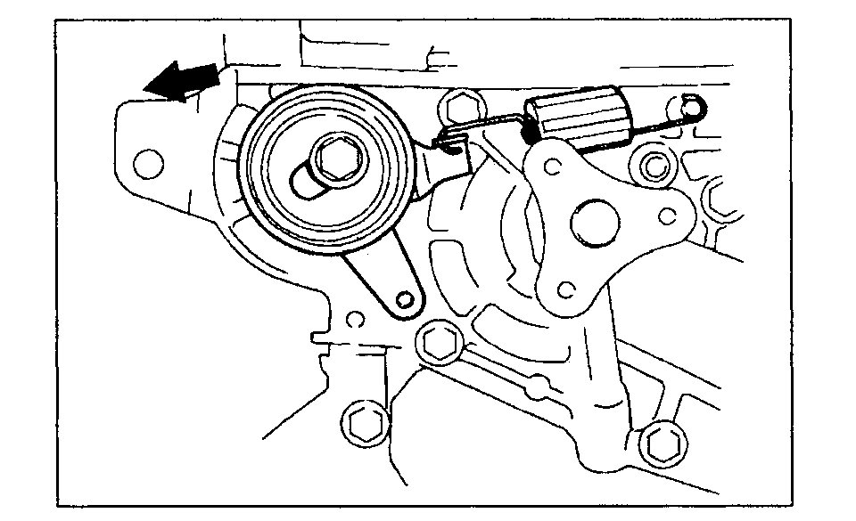
1. Install the tensioner spring as shown.
2. Push the tensioner in the direction of the arrow and hand tighten the lock bolt.
Timing belt
1. Verify that all timing marks are correctly aligned.
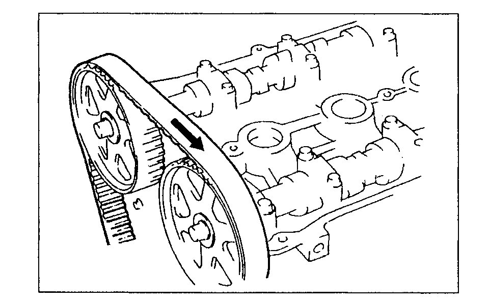
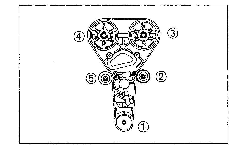
2. Install the timing belt on the pulleys in the order shown below.
1) Timing belt pulley
2) Idler pulley
3) Camshaft pulley (LH)
4) Camshaft pulley (RH)
5) Tensioner
Pulley boss
1. Install the pulley boss and pulley lock bolt. Turn the crankshaft clockwise 1 and 5/6 times, and verify that the timing mark and the tension set mark (A) are aligned.
2. Loosen the tensioner lock bolt to apply tension to the timing belt. Do not apply tension other than that of the tensioner spring.
3. Tighten the tensioner lock bolt.
Tightening torque:
38-51 N-m (3.8-5.3 kgf-m, 28-38 ft-lbf)
4. Turn the crankshaft clockwise 2 and 1/6 times, and verify that all timing marks are correctly aligned.
Note
For the crankshaft side, face the locating pin on the pulley boss straight up.
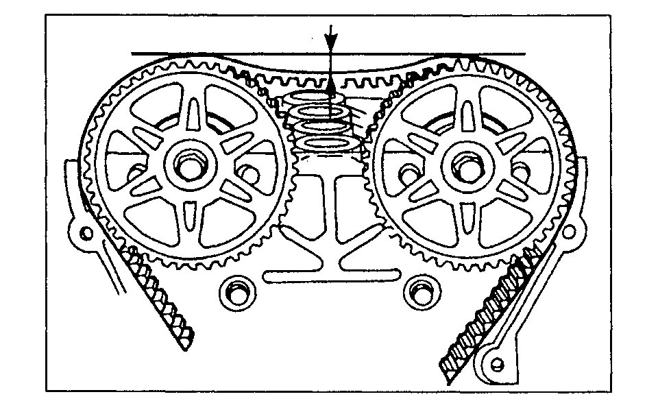
5. Check the belt deflection at the point indicated by applying moderate pressure 98 N (10 kgf, 22 lbf).
Deflection:
9.0-11.5 mm (0.36-0.45 in)
6. If the timing belt deflection is not correct, remove the timing belt and repeat from timing belt assembly note step 1.
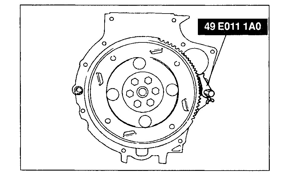
7. Hold the drive plate (ATX) or flywheel (MTX) by using the SST.
8. Tighten the pulley lock bolt.
Tightening torque:
157-166 N-m (16.0-17.0 kgf-m, 116-122 ft-lbf)
Crankshaft pulley and plate
1. Hold the drive plate (ATX) or flywheel (MTX) by using the SST.
2. Install the crankshaft pulley and plate.
Tightening torque:
12.3-17.1 N-m (1.25-1.75 kgf-m, 9.05-12.6 ft-lbf)
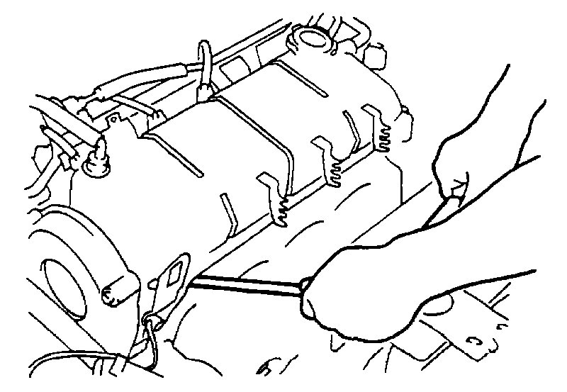
Cylinder head cover
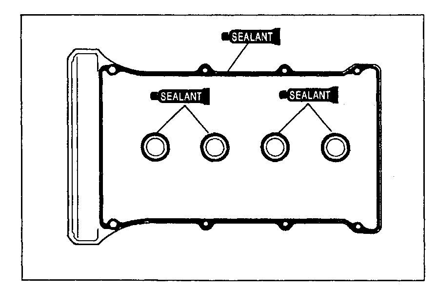
1. Remove all foreign material from the cylinder head cover groove.
2. Apply silicone sealant to the cylinder head cover as shown.
3. Install the new cylinder head cover gasket into the cylinder head cover.
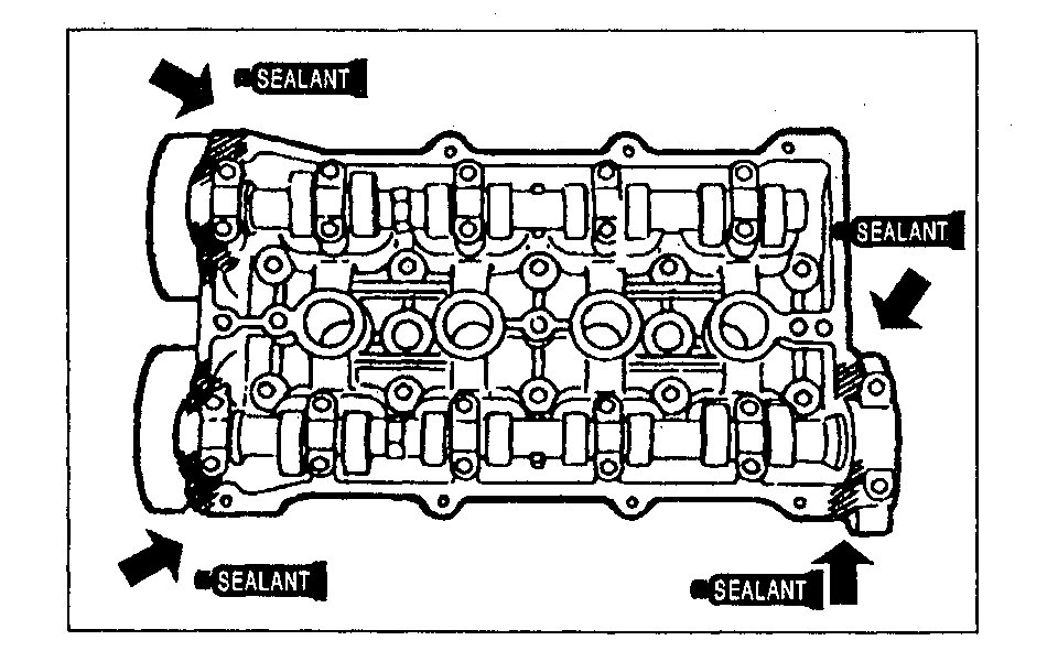
4. Apply silicone sealant to the shaded areas as shown.
5. Install the cylinder head cover.
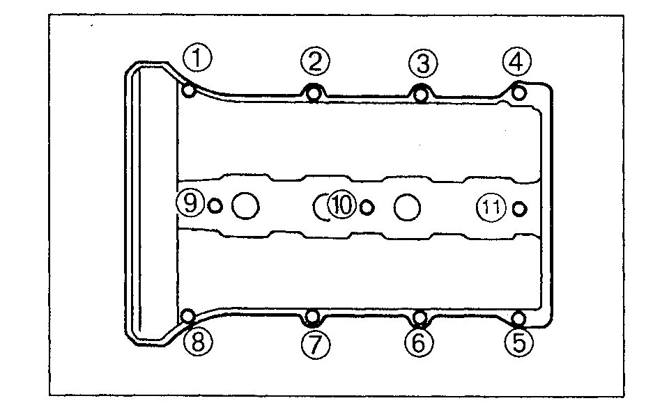
6. Tighten the cylinder head cover bolts in five or six steps in the order shown.
Tightening torque:
5.0-8.8 N-m (50-90 kgf-cm, 44-78 in-lbf)
_________________________
Please feel free to let me know if you have other questions or need help. Also, let me know what you find.
Take care,
Joe
Images (Click to make bigger)
Friday, November 9th, 2018 AT 6:42 PM
