Hi,
If coolant is still coming from there, the water pump is bad. The water pump is driven by the timing chain on this vehicle. The pump shaft is sealed at one end to keep oil in the crankcase and sealed at the other end to keep coolant in the water pump. when either seal leaks, the fluid follows a passage and exits near the thermostat housing just above the AC compressor. I suspect that is what has happened. That opening is basically a weep hole.
___________________________________
Here are the directions for pump replacement. The first 4 pics correlate with these directions. The second set of directions are for timing chain removal and replacement.
__________________________________
2006 Chrysler Sebring Sedan V6-2.7L VIN R
Procedures
Vehicle Engine, Cooling and Exhaust Engine Water Pump Service and Repair Procedures
PROCEDURES
WATER PUMP
REMOVAL
WARNING: Do not remove pressure cap with the system hot and pressurized. Serious burns from coolant can result.
1. Disconnect negative battery cable.
2. Drain cooling system.
NOTE: The water pump is driven by the primary timing chain.
3. Remove the timing chain cover, timing chain, and all chain guides.
Fig. 29
pic 1
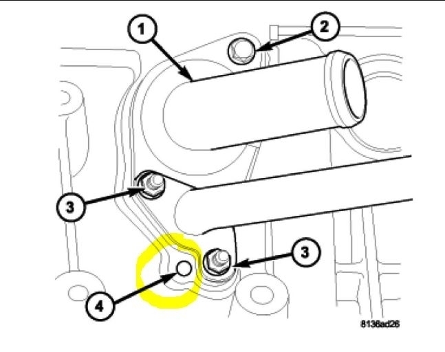
4. Remove bolts attaching water pump to block (Fig. 29).
5. Remove water pump and gasket.
CLEANING
Clean gasket mating surfaces as necessary.
INSPECTION
Inspect and replace the water pump if it has any of the following defects:
1. Damage or cracks on the pump body
Fig. 30
pic 2
Fig. 31
pic 3
2. Coolant leaks: If the shaft seal is leaking, this will be evident by traces of thick deposits of dried glycol running down from the pump primary weep passage (Fig. 30) and (Fig. 31). A thin black stain below the pump primary weep hole/passage is considered normal operation.
Fig. 32
pic 4
3. Coolant leaks: If the pump primary weep passage is plugged, coolant may come from the secondary weep passage and collect in the valley of the engine. The coolant will eventually run out the back side of the engine (Fig. 30) and (Fig. 32). Leakage from the secondary weep passage may give false indications that core plug(s) may be leaking on the back side of the engine block. If this condition is found, clean the primary weep passage of debris.
4. Impeller rubs inside of cylinder block.
5. Excessively loose or rough turning bearing.
NOTE: It is normal for the water pump to weep a small amount of coolant from the primary weep hole (black stain at weep passage). Do not replace the water pump if this condition exists. Replace the water pump if a heavy deposit or a steady flow of engine coolant is evident from the primary weep passage (Fig. 30) and (Fig. 31). This indicates a shaft seal failure and pump must be replaced. Coolant may leak from the secondary weep passage and fill the valley of the engine (Fig. 30) and (Fig. 32). If this condition is found, clean the primary weep passage of debris. Be sure to perform a thorough analysis before replacing water pump.
INSTALLATION
1. Clean all sealing surfaces.
2. Install water pump and gasket. Tighten mounting bolts to 12 Nm (105 inch lbs.).
3. Install timing chain guides, timing chain, and timing chain cover.
4. Reconnect negative battery cable.
5. Fill cooling system.
______________________________________
Here are the directions for chain removal and replacement. If the chain and components are original, I would replace them at the same time.
_____________________________________
2006 Chrysler Sebring Sedan V6-2.7L VIN R
Timing Chain and Sprockets Removal and Installation
Vehicle Engine, Cooling and Exhaust Engine Timing Components Timing Chain Service and Repair Procedures Timing Chain and Sprockets Removal and Installation
TIMING CHAIN AND SPROCKETS REMOVAL AND INSTALLATION
TIMING CHAIN AND SPROCKETS
REMOVAL - TIMING CHAIN
1. Disconnect negative battery cable.
2. Drain cooling system.
3. Remove upper intake manifold.
4. Remove cylinder head covers, crankshaft vibration damper, and timing chain cover.
CAUTION: When aligning timing marks, always rotate engine by turning the crankshaft. Failure to do so will result in valve and/or piston damage.
Fig. 114
pic 5
5. Align crankshaft sprocket timing mark to mark on oil pump housing (Fig. 114). The mark on oil pump housing is 60° ATDC of #1 cylinder.
CAUTION: When the timing chain is removed and the cylinder heads are still installed, DO NOT rotate the camshafts or crankshaft without first locating the proper crankshaft position. Failure to do so will result in valve and/or piston damage.
6. Remove power steering pump and bracket as an assembly. Do not disconnect power steering lines from pump. Reposition pump and support with suitable retaining strap.
Fig. 115
pic 6
7. Remove primary timing chain tensioner retainer cap and tensioner from right cylinder head (Fig. 115).
Fig. 116
pic 7
8. Disconnect and remove camshaft position sensor from left cylinder head (Fig. 116).
9. Remove timing chain guide access plugs from cylinder heads (Fig. 116).
NOTE: When camshaft sprocket bolts are removed, the camshafts will rotate in a clockwise direction.
10. Starting with the right camshaft sprocket, remove the sprocket attaching bolts. Remove camshaft damper (if equipped) and sprocket (Fig. 116).
11. Remove left side camshaft sprocket attaching bolts and remove sprocket (Fig. 116).
12. Remove lower chain guide and tensioner arm (Fig. 116).
13. Remove the primary timing chain.
14. Remove of crankshaft sprocket.
REMOVAL - CRANKSHAFT SPROCKET
1. Remove primary timing chain.
CAUTION: Use care not to turn crankshaft while removing crankshaft sprocket, as damage to valves and or pistons could occur.
Fig. 117
pic 8
2. Remove crankshaft sprocket by first installing the crankshaft damper bolt. Apply grease or equivalent to damper bolt head and position Special Tools 5048-1, 5048-6, and 8539 on sprocket and crankshaft nose (Fig. 117). Remove sprocket using care not to rotate the crankshaft.
INSTALLATION - TIMING CHAIN
1. Inspect all sprockets and chain guides. Replace if worn.
2. Install crankshaft sprocket.
3. If removed, install right and left side short chain guides (Fig. 116). Tighten attaching bolts to 28 Nm (250 inch lbs.).
Fig. 118
pic 9
4. Align crankshaft sprocket timing mark to the mark on oil pump housing (Fig. 118).
NOTE: Lubricate timing chain and guides with engine oil before installation.
5. Place left side primary chain sprocket onto the chain so that the timing mark is located in-between the two (plated) timing links (Fig. 118).
6. Lower the primary chain with left side sprocket through the left cylinder head opening.
NOTE: The camshaft sprockets can be allowed to float on the camshaft hub during installation.
7. Loosely position left side camshaft sprocket over camshaft hub.
8. Align timing (plated) link to the crankshaft sprocket timing mark (Fig. 118).
9. Position primary chain onto water pump drive sprocket.
10. Align right camshaft sprocket timing mark to the timing (plated) link on the timing chain (Fig. 118) and loosely position over camshaft hub.
11. Verify that all chain timing (plated) links are properly aligned to the timing marks on all sprockets (Fig. 118).
12. Install left side lower chain guide and tensioner arm (Fig. 116). Tighten attaching bolts to 28 Nm (250 inch lbs.).
NOTE: Inspect O-ring on chain guide access plugs before installing. Replace O-ring as necessary.
13. Install chain guide access plugs to cylinder heads (Fig. 116). Tighten plugs to 20 Nm (15 ft. lbs.).
Fig. 119
pic 10
NOTE: To reset the primary timing chain tensioner, engine oil will first need to be purged from the tensioner (Fig. 119).
14. Purge oil from timing chain tensioner using the following procedure:
a. Place the check ball end of tensioner into the shallow end of Special Tool 8186 (Fig. 119).
b. Using hand pressure, slowly depress tensioner until oil is purged from tensioner (Fig. 119).
15. Reset timing chain tensioner using the following procedure:
Fig. 120
pic 11
a. Position cylinder plunger into the deeper end of Special Tool 8186 (Fig. 120).
b. Apply a downward force until tensioner is reset (Fig. 120).
NOTE: If oil was not first purged from the tensioner, use slight finger pressure to assist the center arm pin of Special Tool 8186 to unseat the tensioner's check ball.
CAUTION: Ensure the tensioner is properly reset. The tensioner body must bottom against the top edge of Special Tool 8186. Failure to properly perform the resetting procedure may cause tensioner jamming.
16. Install the reset chain tensioner into the right cylinder head (Fig. 115).
17. Position tensioner retaining plate and tighten bolts to 12 Nm (105 inch lbs.). (Fig. 115).
18. Starting at the right cylinder bank, first position the camshaft damper (if equipped) on camshaft hub, then insert a 3/8 square drive extension with a breaker bar into intake camshaft drive hub. Rotate camshaft until the camshaft hub aligns to the camshaft sprocket and damper attaching holes. Install the sprocket attaching bolts and tighten to 28 Nm (250 inch lbs.). (Fig. 116).
19. Turn the left side camshaft by inserting a 3/8 square drive extension with a breaker bar into intake camshaft drive hub and rotate camshaft until the sprocket attaching bolts can be installed. Tighten sprocket bolts to 28 Nm (250 inch lbs.). (Fig. 116).
20. Rotate engine slightly clockwise to remove timing chain slack, if necessary.
Fig. 121
pic 12
21. Activate the timing chain tensioner by using a flat bladed pry tool to gently pry tensioner arm towards the tensioner slightly (Fig. 121). Then release the tensioner arm. Verify the tensioner is activated (extends).
22. Install power steering pump and bracket assembly.
23. Install camshaft position sensor and connect electrical connector.
24. Install the timing chain cover, crankshaft vibration damper, and cylinder head covers.
25. Install upper intake manifold.
NOTE: After installation of a reset tensioner, engine noise will occur after initial start-up. This noise will normally disappear within 5-10 seconds.
26. Fill cooling system.
27. Connect negative battery cable.
INSTALLATION - CRANKSHAFT SPROCKET
Fig. 122
pic 13
1. Install crankshaft sprocket using Special Tools 6780-1 and 8179 (Fig. 122) until sprocket bottoms against crankshaft step flange. Use care not to rotate crankshaft.
Fig. 123
pic 14
2. Verify that crankshaft sprocket is installed to proper depth by measuring from sprocket outer face to end of crankshaft (Fig. 123). Measurement should read: 39.05 ± 0.50 mm (1.5374 ± 0.020 inch).
3. Install primary timing chain.
_____________________________________
I wish I had an easier solution for you. This usually isn't the cause, but in this case, it seems it is. Not the easiest job in the world.
Let me know if I can help, if this takes care of the problem or if you have other questions. Also, confirm timing is correct when you do the work. It can cause internal damage if it is off.
Joe
Images (Click to enlarge)
Dec 12, 2019 at 5:09 PM