Hi,
If you are hearing a clicking when turning, chances are it is a CV joint that is failing. Has someone confirmed it is a ball joint issue? Also, do you know if it is an upper or lower ball joint?
Here is a link that explains in general how one is replaced:
https://www.2carpros.com/articles/how-to-release-a-ball-joint
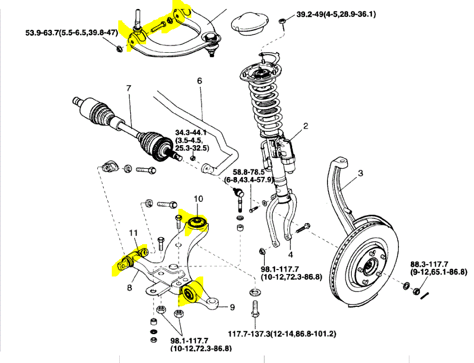
As far as the ball joints on this vehicle, you will need to contact a parts store and make sure they are available. Often times, they sell the entire control arm with the new ball joint included. Actually, at the end of the directions it indicates if the ball joint fails to replace the control arm. If that is the case, here are the directions for both the upper and lower control arms. I will start with the upper. The attached pics correlate with the directions.
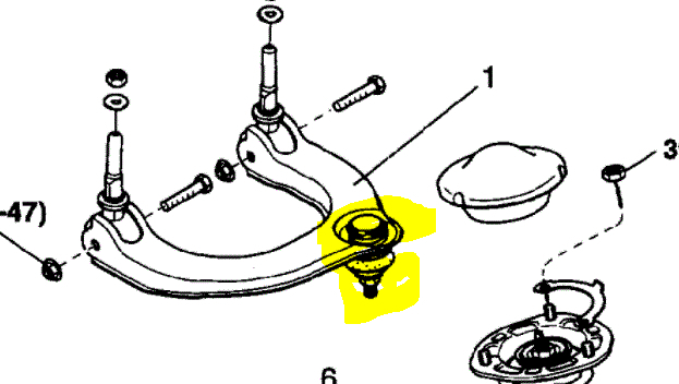
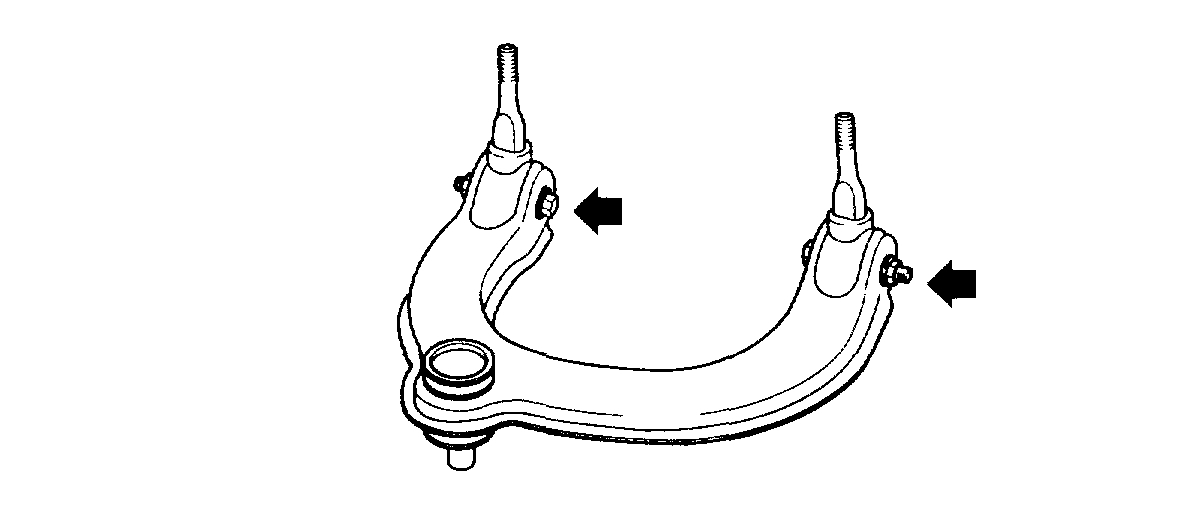
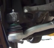
Note: Pic 1 shows the upper ball joint. I highlighted it in the pic.
___________________
2005 Kia Amanti V6-3.5L
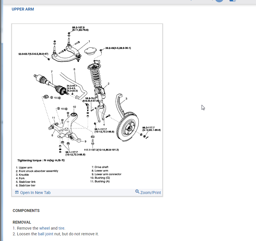
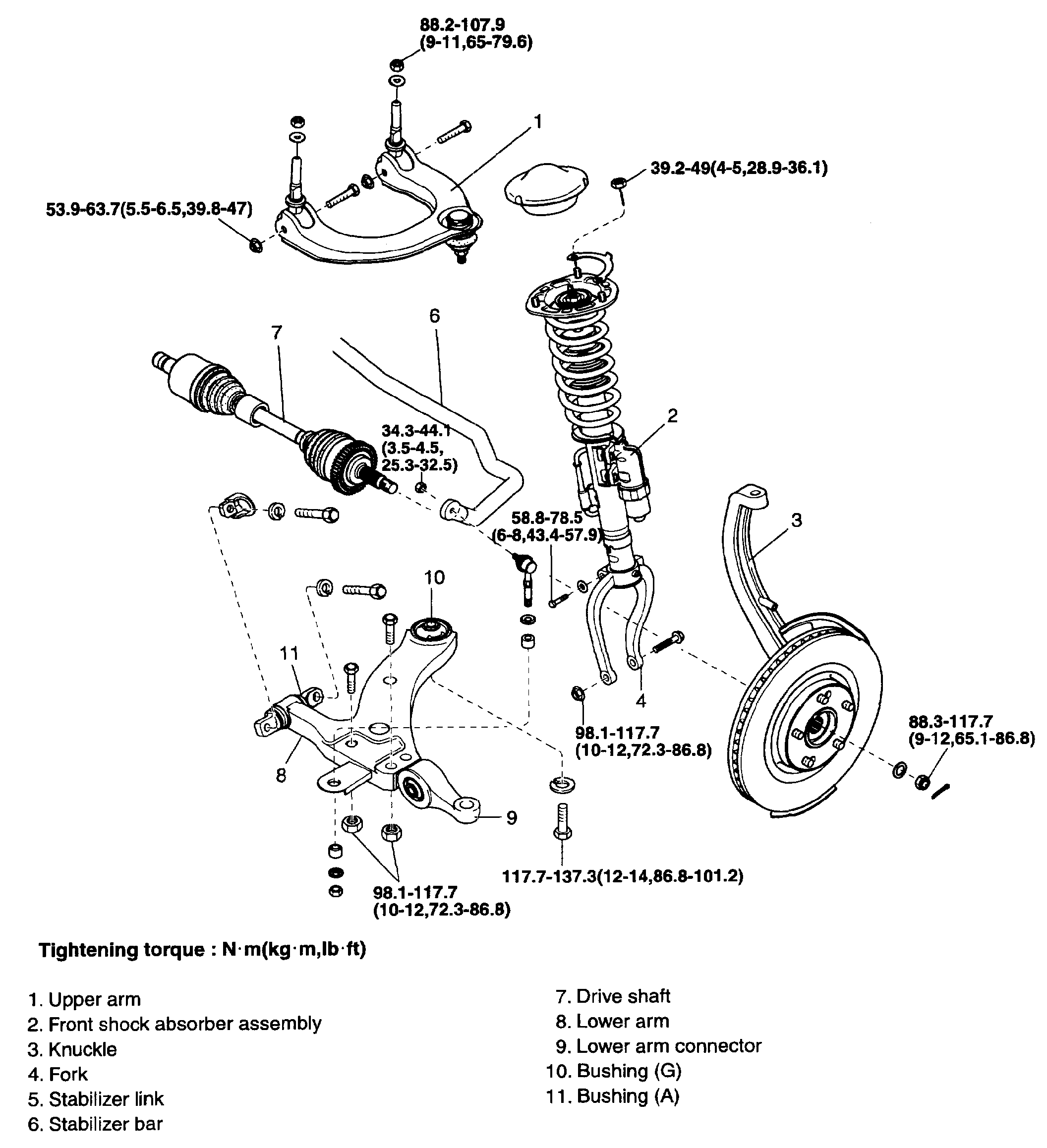
Upper Arm
Vehicle Steering and Suspension Suspension Control Arm Service and Repair Procedures Front Upper Arm
UPPER ARM
UPPER ARM
pic 2
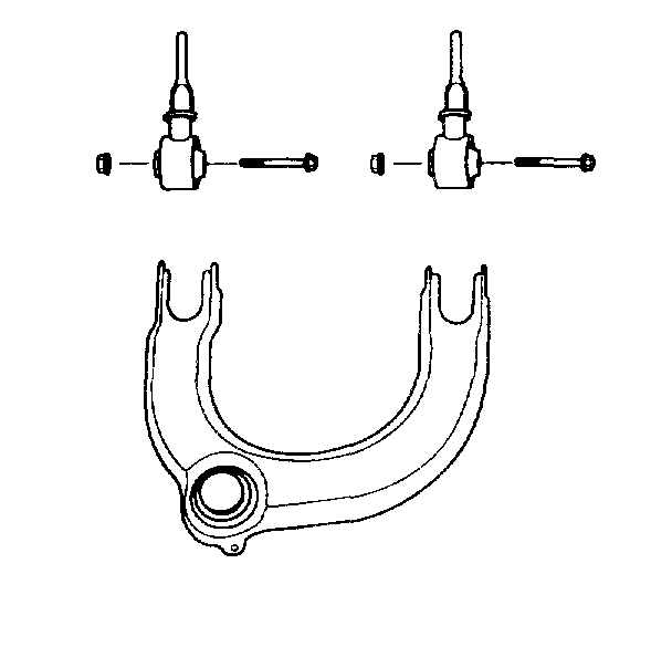
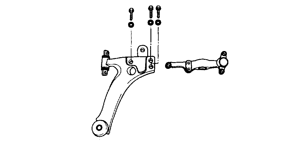
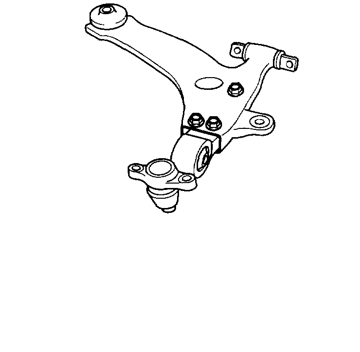
COMPONENTS
REMOVAL
1. Remove the wheel and tire.
2. Loosen the ball joint nut, but do not remove it.
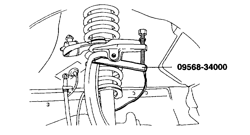
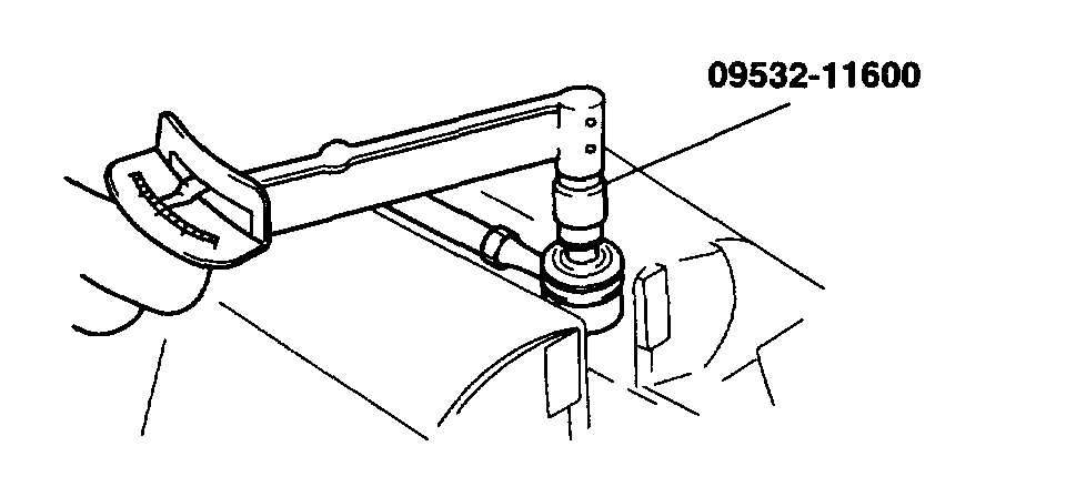
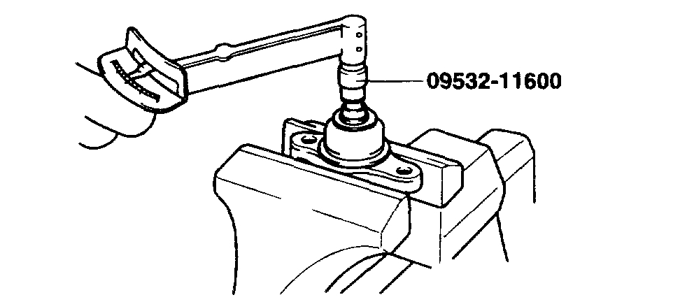
pic 3
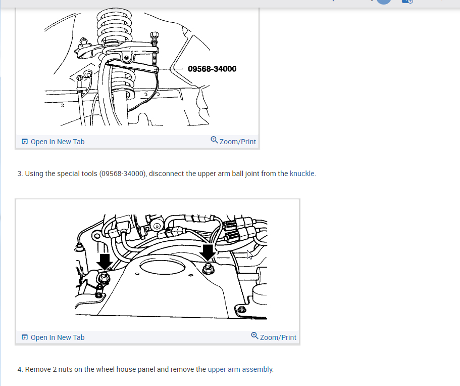
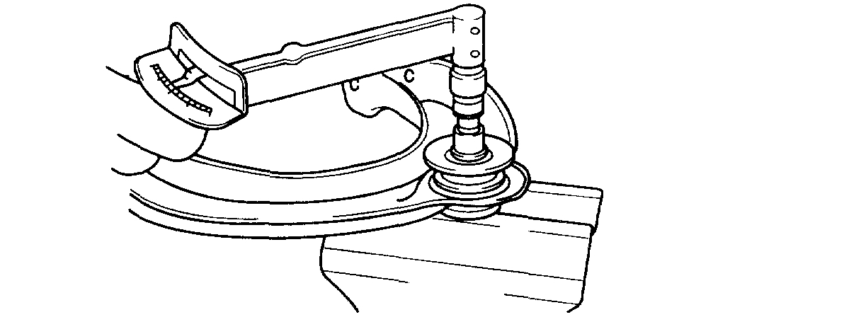
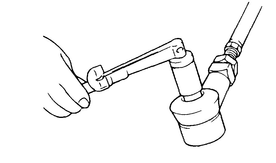
3. Using the special tools (09568-34000), disconnect the upper arm ball joint from the knuckle.
pic 4
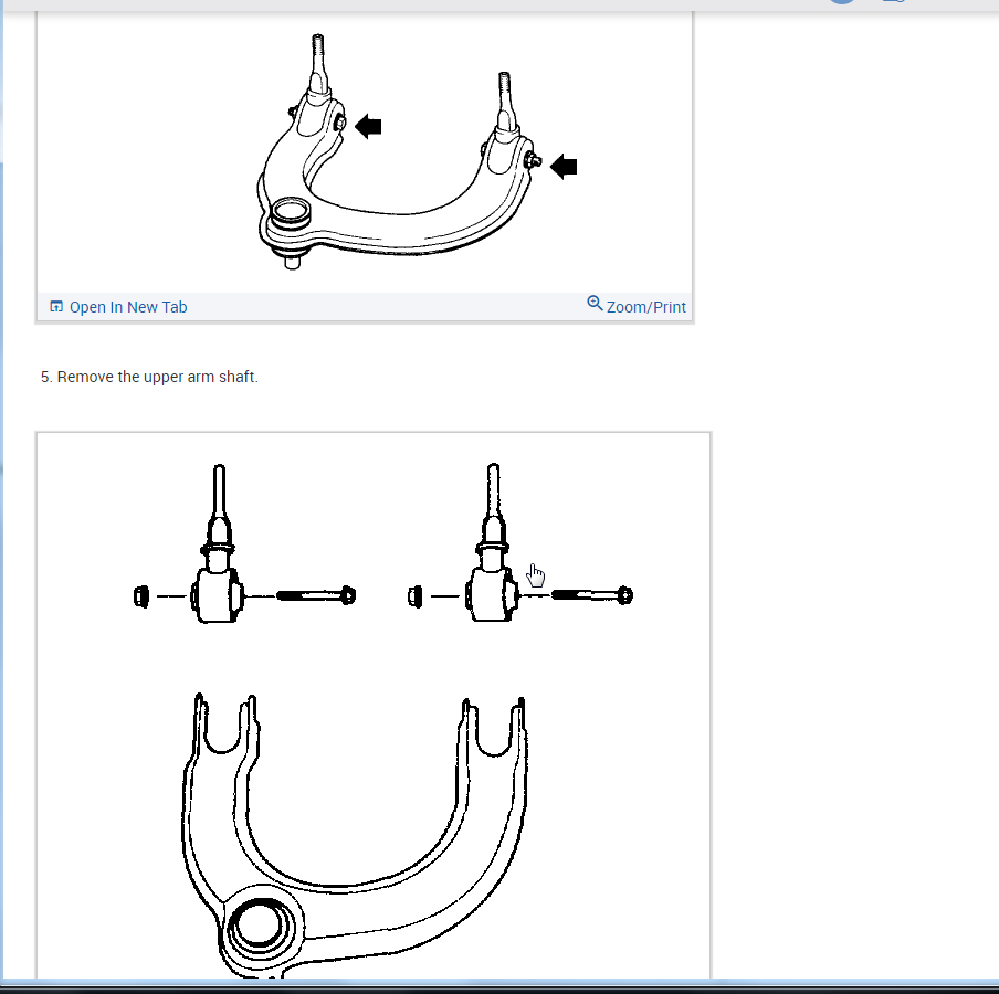
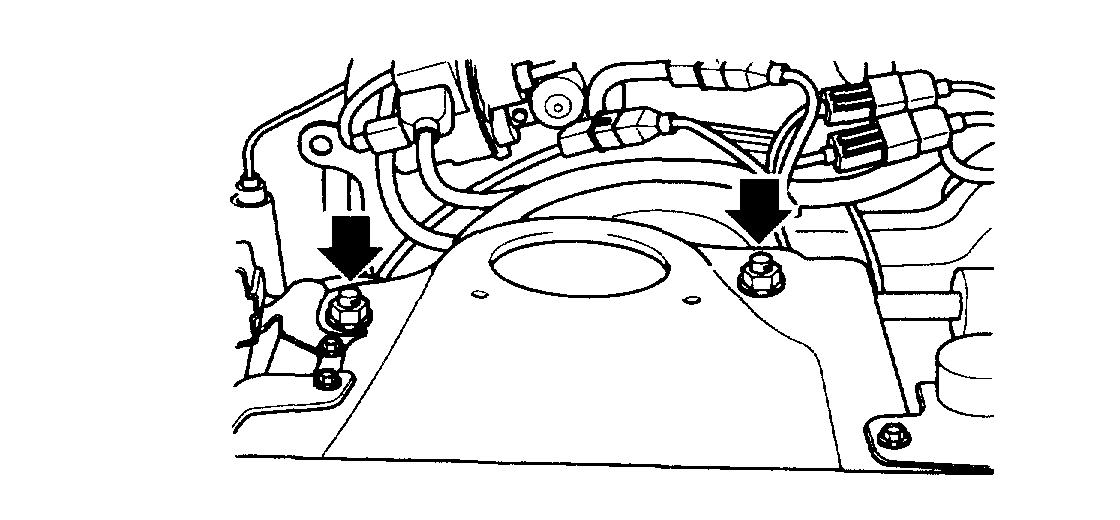
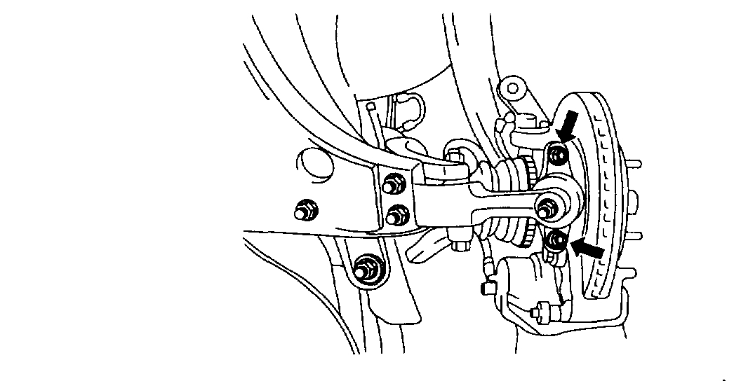
4. Remove 2 nuts on the wheel house panel and remove the upper arm assembly.
pic 5
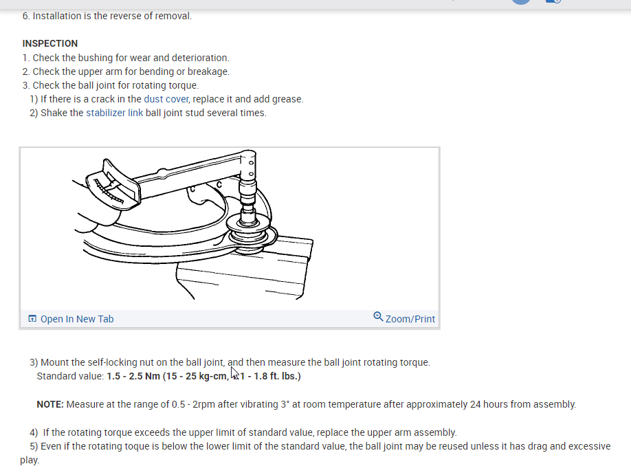
5. Remove the upper arm shaft.
pic 6
6. Installation is the reverse of removal.
INSPECTION
1. Check the bushing for wear and deterioration.
2. Check the upper arm for bending or breakage.
3. Check the ball joint for rotating torque.
1) If there is a crack in the dust cover, replace it and add grease.
2) Shake the stabilizer link ball joint stud several times.
pic 7
3) Mount the self-locking nut on the ball joint, and then measure the ball joint rotating torque.
Standard value: 1.5 - 2.5 Nm (15 - 25 kg-cm, 1.1 - 1.8 ft. lbs.)
NOTE: Measure at the range of 0.5 - 2rpm after vibrating 3° at room temperature after approximately 24 hours from assembly.
4) If the rotating torque exceeds the upper limit of standard value, replace the upper arm assembly.
5) Even if the rotating toque is below the lower limit of the standard value, the ball joint may be reused unless it has drag and excessive play.
___________________________
Lower Replacement
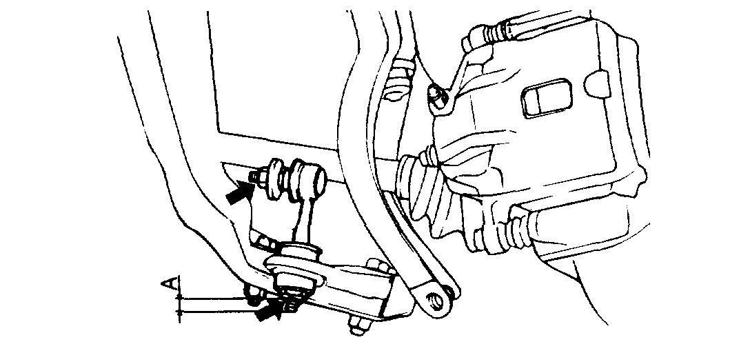
Note: These directions are for the ball joint and bushings. I believe this ball joint is a bolt on, so you should be able to just replace the joint and not the entire control arm. Again, check with the local parts store to confirm if they sale just the joint.
2005 Kia Amanti V6-3.5L
Lower Control Arm
Vehicle Steering and Suspension Suspension Control Arm Service and Repair Procedures Front Lower Control Arm
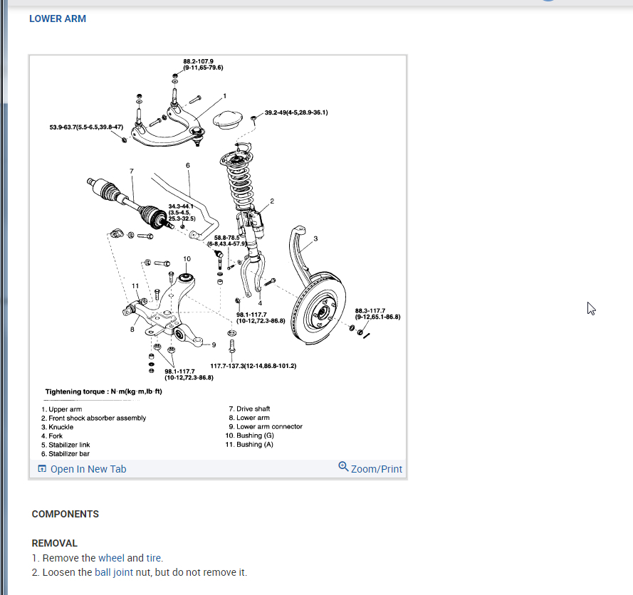
LOWER CONTROL ARM
LOWER ARM
pic 8
COMPONENTS
REMOVAL
1. Remove the wheel and tire.
2. Loosen the ball joint nut, but do not remove it.
pic 9
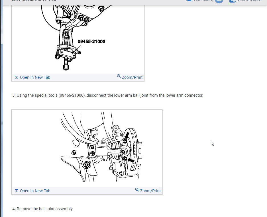
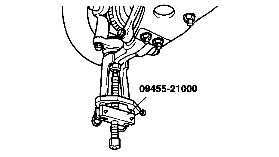
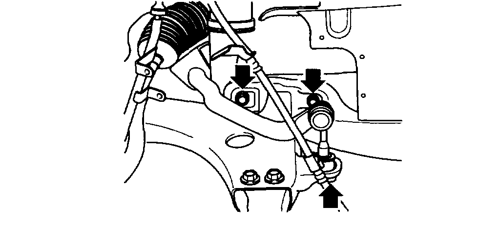
3. Using the special tools (09455-21000), disconnect the lower arm ball joint from the lower arm connector.
pic 10
4. Remove the ball joint assembly.
pic 11
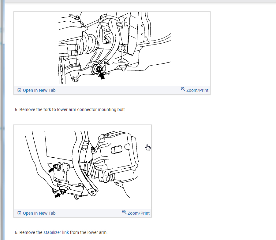
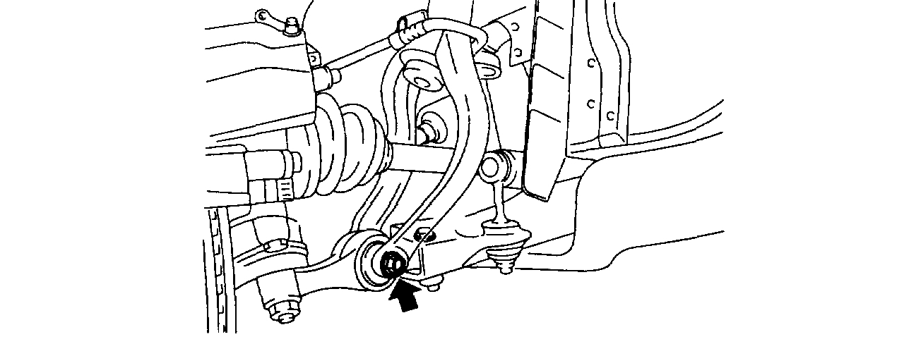
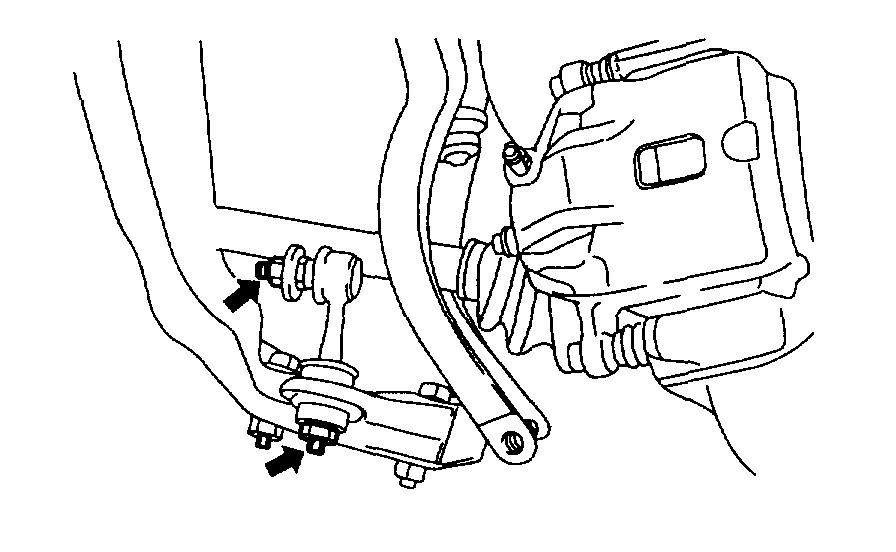
5. Remove the fork to lower arm connector mounting bolt.
pic 12
6. Remove the stabilizer link from the lower arm.
pic 13
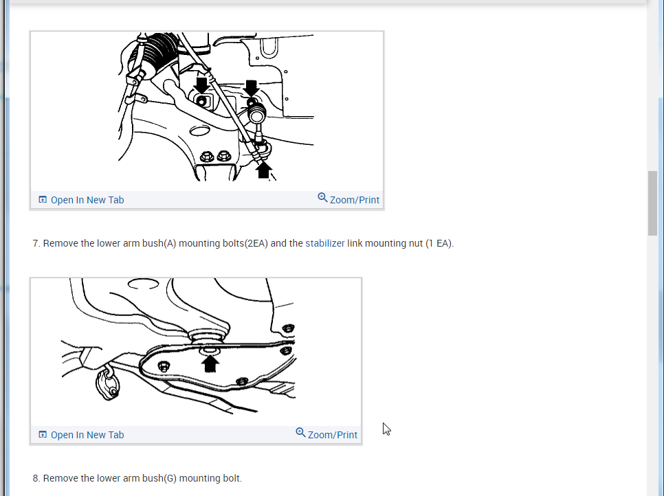
7. Remove the lower arm bush(A) mounting bolts(2EA) and the stabilizer link mounting nut (1 EA).
pic 14
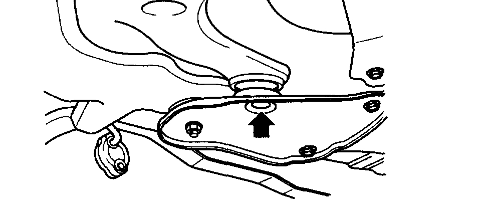
8. Remove the lower arm bush(G) mounting bolt.
DISASSEMBLY
pic 15
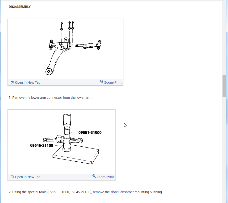
1. Remove the lower arm connector from the lower arm.
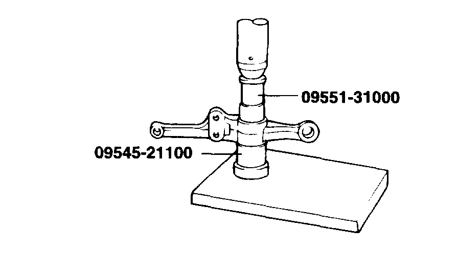
pic 16
2. Using the special tools (09551 -31000, 09545-21100), remove the shock absorber mounting bushing.
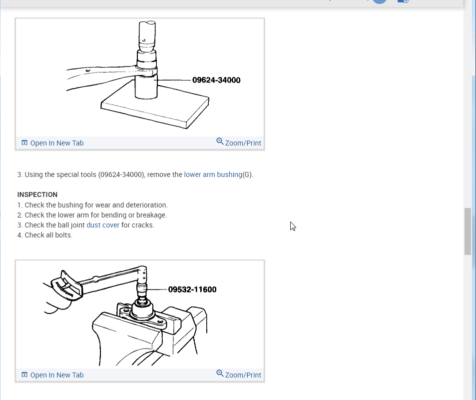
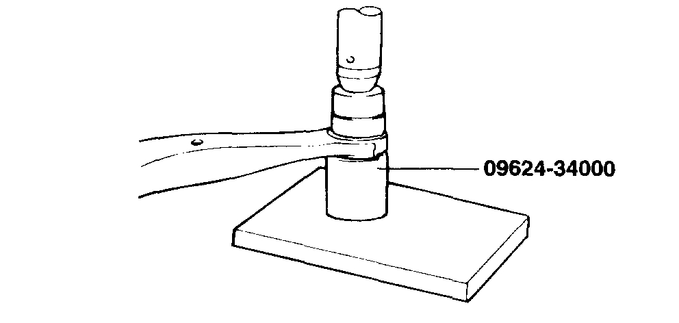
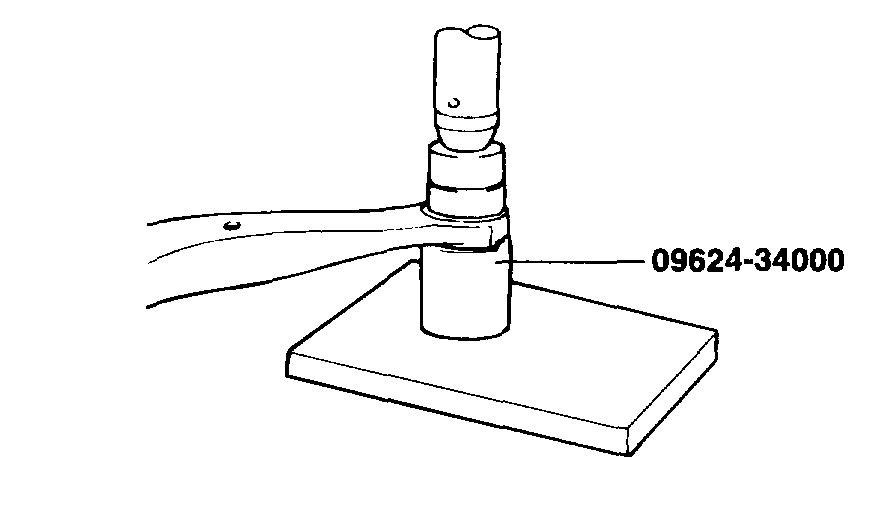
pic 17
3. Using the special tools (09624-34000), remove the lower arm bushing(G).
INSPECTION
1. Check the bushing for wear and deterioration.
2. Check the lower arm for bending or breakage.
3. Check the ball joint dust cover for cracks.
4. Check all bolts.
pic 18
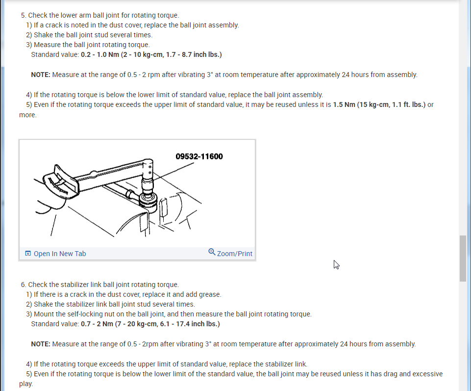
5. Check the lower arm ball joint for rotating torque.
1) If a crack is noted in the dust cover, replace the ball joint assembly.
2) Shake the ball joint stud several times.
3) Measure the ball joint rotating torque.
Standard value: 0.2 - 1.0 Nm (2 - 10 kg-cm, 1.7 - 8.7 inch lbs.)
NOTE: Measure at the range of 0.5 - 2 rpm after vibrating 3° at room temperature after approximately 24 hours from assembly.
4) If the rotating torque is below the lower limit of standard value, replace the ball joint assembly.
5) Even if the rotating torque exceeds the upper limit of standard value, it may be reused unless it is 1.5 Nm (15 kg-cm, 1.1 ft. lbs.) or more.
pic 19
6. Check the stabilizer link ball joint rotating torque.
1) If there is a crack in the dust cover, replace it and add grease.
2) Shake the stabilizer link ball joint stud several times.
3) Mount the self-locking nut on the ball joint, and then measure the ball joint rotating torque.
Standard value: 0.7 - 2 Nm (7 - 20 kg-cm, 6.1 - 17.4 inch lbs.)
NOTE: Measure at the range of 0.5 - 2rpm after vibrating 3° at room temperature after approximately 24 hours from assembly.
4) If the rotating torque exceeds the upper limit of standard value, replace the stabilizer link.
5) Even if the rotating torque is below the lower limit of the standard value, the ball joint may be reused unless it has drag and excessive play.
REASSEMBLY
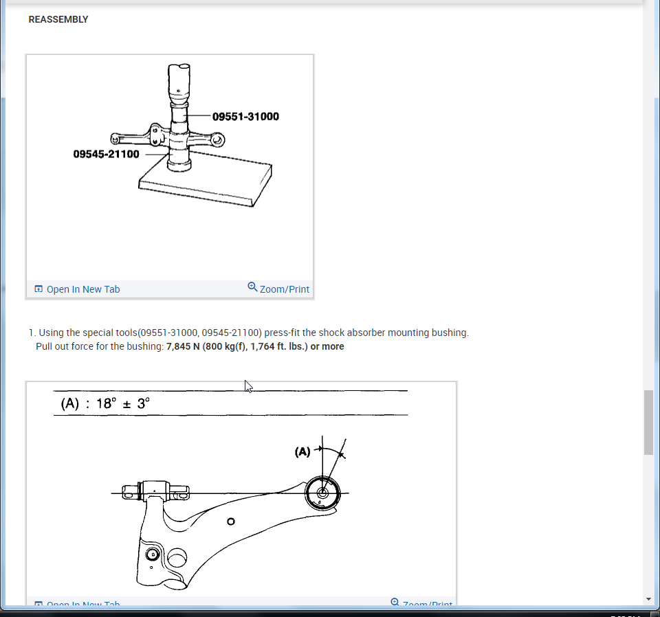
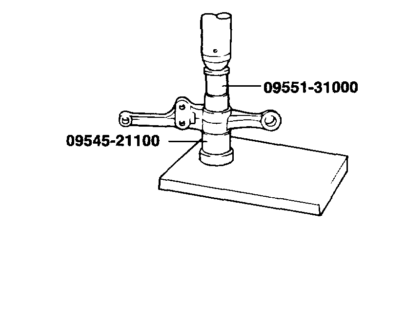
pic 20
1. Using the special tools(09551-31000, 09545-21100) press-fit the shock absorber mounting bushing.
Pull out force for the bushing: 7,845 N (800 kg(f), 1,764 ft. lbs.) or more
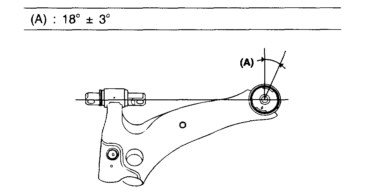
pic 21
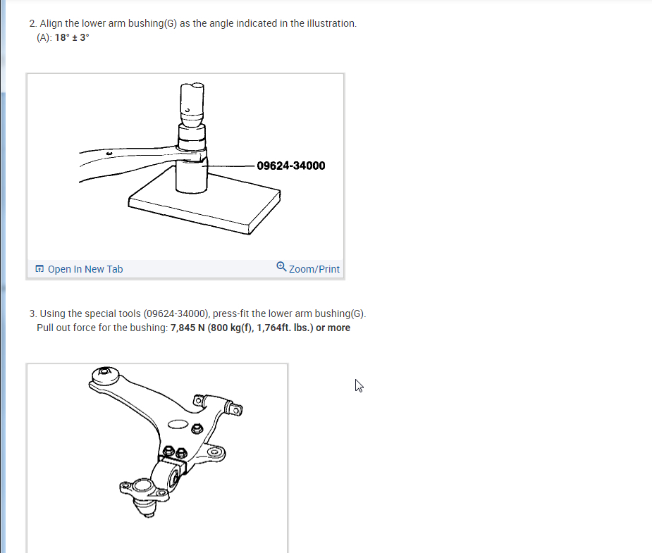
2. Align the lower arm bushing(G) as the angle indicated in the illustration.
(A): 18° ± 3°
pic 22
3. Using the special tools (09624-34000), press-fit the lower arm bushing(G).
Pull out force for the bushing: 7,845 N (800 kg(f), 1,764ft. lbs.) or more
pic 23
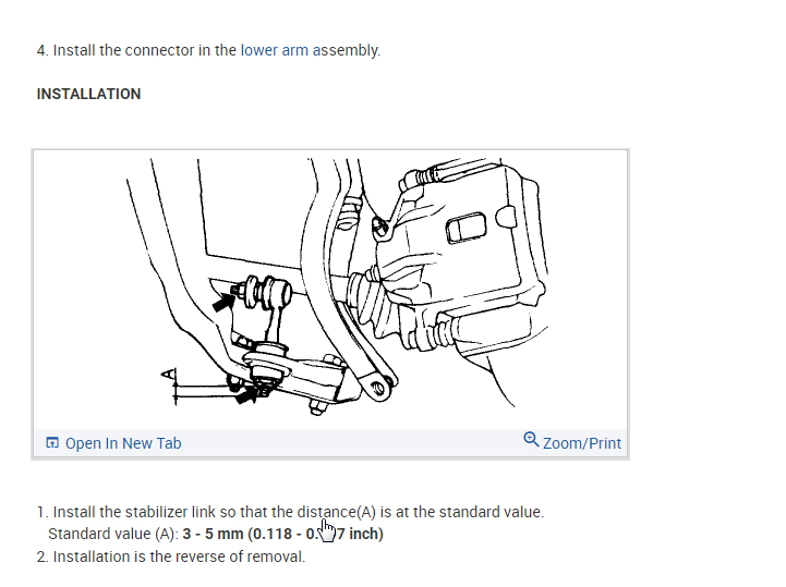
4. Install the connector in the lower arm assembly.
INSTALLATION
1. Install the stabilizer link so that the distance(A) is at the standard value.
Standard value (A): 3 - 5 mm (0.118 - 0.197 inch)
2. Installation is the reverse of removal.
_____________________________________________________________________________
I hope this helps. Let me know if you have other questions.
Take care,
Joe
Images (Click to make bigger)
Saturday, November 7th, 2020 AT 4:43 PM