Good morning,
I attached the 742 to your other post.
The 133 is below. It could be anything from the sensor itself or an electrical issue. If you have a voltmeter, we can do some checks.
https://www.2carpros.com/articles/how-to-check-wiring
https://www.2carpros.com/articles/how-to-use-a-voltmeter
I attached some guides for you for the sensor.
https://www.2carpros.com/articles/how-an-oxygen-sensor-works
https://www.2carpros.com/articles/how-to-replace-an-oxygen-sensor
Roy
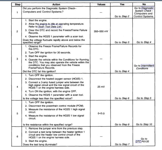
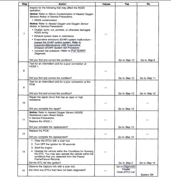
DTC P0133
CIRCUIT DESCRIPTION
Heated oxygen sensors (HO2S) are used for fuel control and post catalyst monitoring. Each HO2S compares the oxygen content of the surrounding air with the oxygen content of the exhaust stream. When the vehicle is first started, the powertrain control module (PCM) operates in an Open Loop mode, ignoring the HO2S signal voltage when calculating the air-to-fuel ratio. The PCM supplies the HO2S with a reference, or bias, voltage of about 450 mV. The HO2S generates a voltage within a range of 0-1,000 mV that fluctuates above and below bias voltage once the sensor reaches operating temperature. A high HO2S voltage output indicates a rich fuel mixture. A low HO2S voltage output indicates a lean mixture. Heating elements inside the HO2S minimize the time required for the sensors to reach operating temperature and provide an accurate voltage signal. If the PCM detects that the HO2S 1 voltage average response time is too slow, DTC P0133 will set. This DTC runs once per trip. Each HO2S has the following circuits:
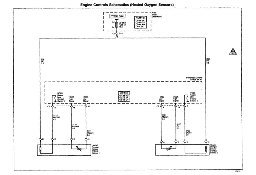
- HO2S 1 high signal circuit
- HO2S 1 low signal circuit
- HO2S 1 heater ignition 1 voltage circuit
- HO2S 1 heater low control circuit
CONDITIONS FOR RUNNING THE DTC
- DTCs P0030, P0101, P0102, P0103, P0107, P0108, P0112, P0113, P0117, P0118, P0120, P0131, P0132, P0134, P0135, P0201, P0202, P0203, P0204, P0205, P0206, P0220, P0300, P0442, P0443, P0446, P0449, P0455, P0496, P1106, P1107, P1111, P1112, P1114, P1115, P2135 are not set.
- The vehicle is not in Park, Reverse, or Neutral.
- DTCs P0136, P0401, and P0420 passed.
- The Engine Run Time parameter is at least 60 seconds.
- The Loop Status parameter is closed.
- The MAF Sensor parameter is between 15-31 g/s.
- The Engine Speed parameter is between 1,300-3,150 RPM.
- The TP Indicated Angle parameter is more than 2 percent.
- The ECT Sensor parameter is more than 65°C (149°F).
- The system voltage is between 9-18 volts.
- The EVAP System is purging.
- The HO2S 1 Heater Command parameter is ON.
- The above conditions have been met for 2 seconds.
CONDITIONS FOR SETTING THE DTC
The PCM detects that the HO2S 1 rich-to-lean and lean-to-rich transition time takes longer than a calibrated value.
ACTION TAKEN WHEN THE DTC SETS
- The control module illuminates the malfunction indicator lamp (MIL) on the second consecutive ignition cycle that the diagnostic runs and fails.
- The control module records the operating conditions at the time the diagnostic fails. The first time the diagnostic fails, the control module stores this information in the Failure Records. If the diagnostic reports a failure on the second consecutive ignition cycle, the control module records the operating conditions at the time of the failure. The control module writes the operating conditions to the Freeze Frame and updates the Failure Records.
CONDITIONS FOR CLEARING THE MIL/DTC
- The control module turns OFF the malfunction indicator lamp (MIL) after 3 consecutive ignition cycles that the diagnostic runs and does not tail.
- A current DTC, Last Test Failed, clears when the diagnostic runs and passes.
- A history DTC clears after 40 consecutive warm-up cycles, if no failures are reported by this or any other emission related diagnostic.
- Clear the MIL and the DTC with a scan tool.
HEATED OXYGEN SENSOR (HO2S) 1 REPLACEMENT
TOOLS REQUIRED
J 39194 Oxygen Sensor Wrench
NOTE: The Heated Oxygen Sensor (HO2S) and the Oxygen Sensor use a permanently attached pigtail and connector. Do not remove this pigtail from the Heated Oxygen Sensor. Damage or the removal of the pigtail or the connector could affect the proper operation of the sensor.
Take care when handling the HO2S and the O2S. Keep the in-line electrical connector and the louvered end free of grease, dirt, or other contaminants. Also avoid using cleaning solvents of any type. Do not drop the HO2S or the O2S. Do not roughly handle the HO2S or the O2S.
REMOVAL PROCEDURE
NOTE: The oxygen sensor may be difficult to remove when the engine temperature is below 48°C (120°F). Excessive force may damage threads in the exhaust manifold or the exhaust pipe.
imageOpen In New TabZoom/Print
1. Remove the fuel injector sight shield.
2. Remove the heated oxygen sensor (HO2S) retaining clip.
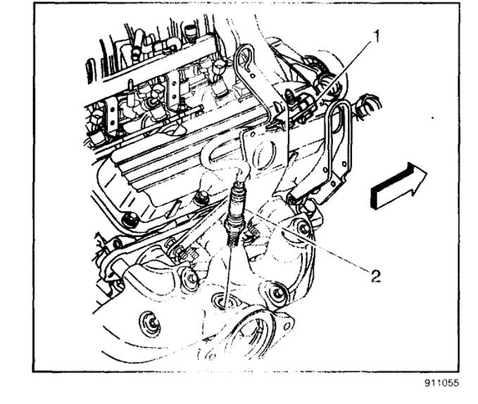
3. Disconnect the HO2S electrical connector (1).
4. Remove the HO2S electrical connector (1) from the fuel injector sight shield bracket.
IMPORTANT: Remove the oxygen sensors with the engine temperature above 48°C (120°F). Otherwise the oxygen sensors may be difficult to remove.
5. Use the J 39194 to remove the HO2S (2) from the right exhaust manifold.
INSTALLATION PROCEDURE
NOTE:
- Refer to Heated Oxygen Sensor (HO2S) Resistance Learn Reset Note in Service Precautions.
- Refer to Fastener Note in Service Precautions.
IMPORTANT: A special anti-seize compound is used on the oxygen sensor (1) threads. New service sensors should already have the compound applied to the threads. Coat the threads of a reused sensor with anti-seize compound GM P/N 12377953 or equivalent.
imageOpen In New TabZoom/Print
1. Install the HO2S (2) to the right exhaust manifold.
Tighten
Use the J 39194 to tighten the HO2S to 42 N.m (31 lb ft).
2. Install the HO2S electrical connector (1) to the fuel injector sight shield bracket.
3. Connect the HO2S electrical connector (1).
4. Install the HO2S retaining clip.
5. Install the fuel injector sight shield.
Images (Click to make bigger)
Sunday, March 28th, 2021 AT 6:52 AM