Okay.
The 11 code is the intake cam sensor.
the fact that there are cam sensor codes, verify there is 5 volts to the sensor connectors. if there is, check the connectors. if they are good, it is possible the sensors are bad but the possibility of a timing issue is strong between the cams and the crank
Roy
DTC P0010, P0011, P0013, P0014, P0020, P0021, P0023, or P0024
DIAGNOSTIC INSTRUCTIONS
- Perform the Diagnostic System Check - Vehicle prior to using this diagnostic procedure. See: Vehicle > Initial Inspection and Diagnostic Overview
- Review Strategy Based Diagnosis for an overview of the diagnostic approach.
- Diagnostic Procedure Instructions provides an overview of each diagnostic category.
DTC DESCRIPTORS
DTC P0010
Intake Camshaft Position (CMP) Actuator Solenoid Control Circuit Bank 1
DTC P0011
Intake Camshaft Position (CMP) System Performance Bank 1
DTC P0013
Exhaust Camshaft Position (CMP) Actuator Solenoid Control Circuit Bank 1
DTC P0014
Exhaust Camshaft Position (CMP) System Performance Bank 1
DTC P0020
Intake Camshaft Position (CMP) Actuator Solenoid Control Circuit Bank 2
DTC P0021
Intake Camshaft Position (CMP) System Performance Bank 2
DTC P0023
Exhaust Camshaft Position (CMP) Actuator Solenoid Control Circuit Bank 2
DTC P0024
Exhaust Camshaft Position (CMP) System Performance Bank 2
image
DIAGNOSTIC FAULT INFORMATION
CIRCUIT/SYSTEM DESCRIPTION
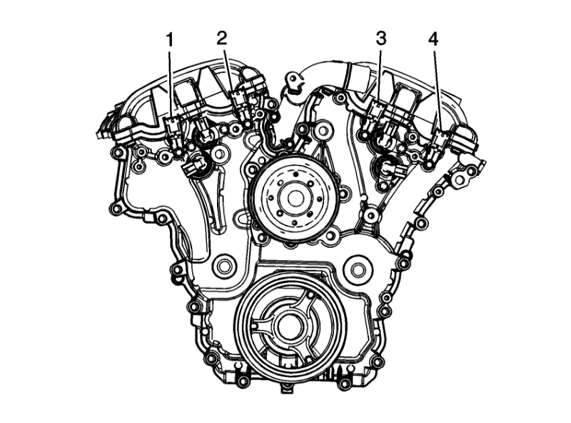
The camshaft position (CMP) actuator is attached to each camshaft and is hydraulically operated in order to change the angle of the camshaft relative to crankshaft position (CKP). The CMP actuator solenoid is controlled by the engine control module (ECM). The ECM sends a pulse width modulated 12-volt signal to each CMP actuator solenoid. The solenoid controls the amount of engine oil flow to the CMP actuator by extending a pintle within the solenoid. The pintle acts against a spool valve in the CMP actuator mechanism which is attached to the front of each camshaft. As the spool valve is moved, oil is directed to the CMP actuator, which rotates the camshaft. The CMP actuator can change the cam angle a maximum of 27 degrees.
CONDITIONS FOR RUNNING THE DTC
P0010, P0013, P0020, or P0023
- The ignition is in Crank or Run.
- The system voltage is between 11-18 volts.
- DTCs P0010, P0013, P0020, and P0023 run continuously when the above conditions are met.
P0011, P0014, P0021, or P0024
- DTCs P0010, P0016, P0017, P0018, P0019, P0335, P0336, P0340, P0341, P0345, P0346, P0365, P0366, P0390, or P0391 are not set.
- The system voltage is between 11-18 volts.
- The engine is running.
- The ECM has enabled the CMP actuator and commanded greater than 0 degrees.
- DTC P0011, P0014, P0021, P0024 runs continuously when the above conditions are met.
CONDITIONS FOR SETTING THE DTC
P0010, P0013, P0020, or P0023
The ECM detects that the state of the driver and the state of the circuit do not match. The ECM will detect an open, short to ground, or a short to voltage on the high control circuit or an open on the low reference circuit for more than 3.0 seconds.
P0011, P0014, P0021, or P0024
1. Each CMP angle from the ECM is stable. If the CMP angle varies more than 4.5 cam degrees, then a stability timer of 1 second must expire before evaluating fail condition.
2. The difference between the desired CMP and the actual CMP angle is more than 5 degrees for 10 seconds during a 300-second sample.
ACTION TAKEN WHEN THE DTC SETS
- DTCs P0010, P0011, P0013, P0014, P0020, P0021, P0023, P0024 are Type B DTCs.
- The CMP actuators are commanded to the home or parked position.
CONDITIONS FOR CLEARING THE MIL/DTC
DTCs P0010, P0011, P0013, P0014, P0020, P0021, P0023, P0024 are Type B DTCs.
CIRCUIT/SYSTEM VERIFICATION
1. IMPORTANT: The supply of clean pressurized engine oil to the CMP actuator is essential to CMP actuator performance.
Observe the engine oil level. The engine oil level should be within operating range. Refer to Approximate Fluid Capacities.
2. Ensure that the vehicle has the correct engine oil and is not old, burnt or contains additives. Refer to Checking Things Under the Hood in Service and Appearance Care within the Owner's Manual.
- If the vehicle has the incorrect engine oil, is old, burnt, or contains additives then change the oil and filter.
3. Test the engine oil pressure for correct operation. Refer to Oil Pressure Diagnosis and Testing. See: Engine Oil Pressure > Component Tests and General Diagnostics
4. Allow the engine to reach operating temperature.
5. Set the parking brake and place the vehicle in park for automatic, or neutral for manual.
6. Observe the applicable CMP variance parameter. The CMP Variance will rise for 1-2 seconds until the CMP Angle parameter matches the Desired CMP parameter. The CMP Variance should again return to 0 degrees.
7. IMPORTANT: The engine will run rough and may require throttle input to keep running.
Command the applicable CMP actuator to 20 degrees. The Desired CMP parameter should match the CMP Angle parameter.
CIRCUIT/SYSTEM TESTING
IMPORTANT: You must complete the Circuit/System Verification before proceeding with
P0010, P0013, P0020, or P0023
1. Ignition OFF, disconnect the affected CMP actuator solenoid harness connector at the CMP actuator solenoid.
2. Test for less than 1 ohm of resistance between the low reference circuit and ground.
- If greater than 1 ohm, test the low reference for an open/high resistance. If the circuit tests normal replace the ECM.
3. Connect a test lamp between the high control circuit and the low reference circuit.
4. Command the affected CMP actuator solenoid ON and OFF. The test lamp should turn ON and OFF when changing between commanded states.
- If the test lamp is always ON, test the high control circuit for a short to voltage. If the circuit tests normal replace the ECM.
- If test lamp is always OFF, test the control circuit for a short to ground, an open/high resistance. If the circuit tests normal replace the ECM.
5. If all circuits test normal, test or replace the applicable CMP Actuator solenoid.
P0011, P0014, P0021, or P0024
- Test for less than 1 ohm of resistance between the applicable CMP actuator solenoid low reference circuit and ground.
- If greater than 1 ohm, test the low reference for an open/high resistance. If the circuit tests normal, replace the applicable CMP actuator solenoid.
- Test for less than 1 ohm of resistance on the applicable CMP actuator solenoid high control circuit.
- If greater than 1 ohm, test the high control circuit for an open/high resistance. If the circuit tests normal, replace the applicable CMP actuator solenoid.
- Inspect the affected CMP actuator.
- Inspect the engine timing components.
COMPONENT TESTING
Static Test
1. Ignition OFF, disconnect the CMP actuator solenoid harness connector at the CMP actuator solenoid.
2. IMPORTANT: Ensure component is tested at 20°C (68°F).
Test for 4.6-7.5 ohms of resistance between the high control terminal A and the low reference terminal B of the CMP actuator solenoid.
- If the resistance is not within the specified range, replace the CMP actuator solenoid.
Dynamic Test
1. IMPORTANT: Do not allow the solenoid to be energized for more than 2 seconds.
Install fused jumper wire between the high control and 12 volts. Install a jumper wire between the low reference and momentarily connect to ground.
2. Point the CMP actuator solenoid towards a shop towel. Observe the operation of the solenoid immediately extends.
- If the function does not perform as specified, replace the CMP actuator solenoid.
REPAIR INSTRUCTIONS
Perform the Diagnostic Repair Verification after completing the diagnostic procedure. See: A L L Diagnostic Trouble Codes ( DTC ) > Verification Tests
- Refer to Programming and Relearning for ECM setup, and programming. See: Vehicle > Programming and Relearning
- Camshaft Position Actuator Replacement - Bank 2 (Left Side) Exhaust
- Camshaft Position Actuator Replacement - Bank 1 (Right Side) Exhaust
- Camshaft Position Actuator Replacement - Bank 2 (Left Side) Intake
- Camshaft Position Actuator Replacement - Bank 1 (Right Side) Intake
- Camshaft Timing Drive Components Cleaning and Inspection (Fourth Design) for timing chain, sprockets, CMP actuator filter screen, and CMP actuator replacement.
Apr 6, 2018 at 12:02 PM