Hi,
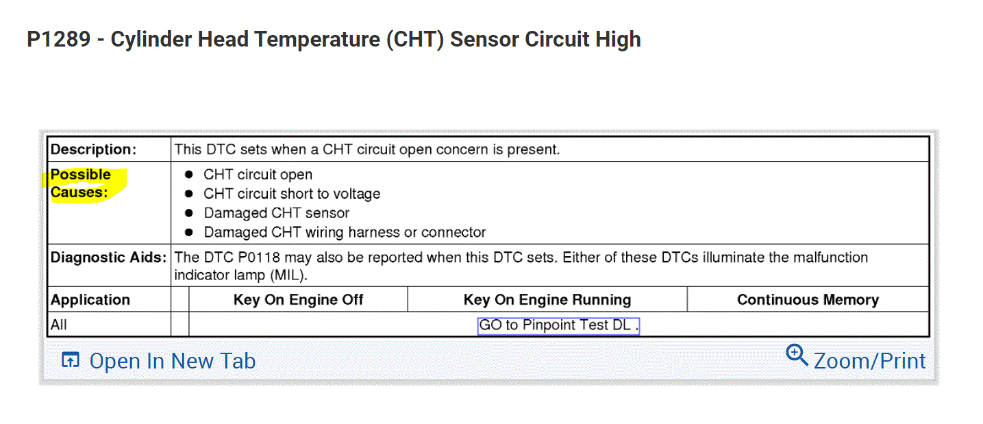
If the engine was cold and you got that code, either the sensor is bad or there is a wiring issue. If you look at the last pic below, it shows the possible causes.
We have two choices here. Chances are the sensor is bad, but if you want to be sure, I have the diagnostics for the system. It is very extensive. Here it is.
If you want to try replacing it, see directions after the diagnostics.
___________________________
2015 Ford Truck Explorer 4WD V6-3.5L
DL: Cylinder Head Temperature (CHT) Sensor - Pinpoint Test
Vehicle Powertrain Management Computers and Control Systems Testing and Inspection Diagnostic Trouble Code Tests and Associated Procedures Powertrain Control / Emission Diagnostics (PCED) SECTION 5: Pinpoint Tests DL: Cylinder Head Temperature (CHT) Sensor - Pinpoint Test
DL: CYLINDER HEAD TEMPERATURE (CHT) SENSOR - PINPOINT TEST
DL: Cylinder Head Temperature (CHT) Sensor
DL: Introduction See: Computers and Control Systems > Diagnostic Trouble Code Tests and Associated Procedures > DL: Cylinder Head Temperature (CHT) Sensor - Introduction
DL1 CHECK FOR DTCS
Are DTCs P0116, P0119, P0125, P0128, P017C, P017D, P017E, P101F, P1021, P1022, P1023, P1024, P1025, P1026, P1285, P1288, P1289, P128A, or P1290 present?
Yes
- GO to DL2
.
No
- For temperature warning indicator lamp or gauge (applications with CHT sensor only) symptom, GO to DL12
.
- For all others, RETURN to Section 3 See: Computers and Control Systems > Diagnostic Trouble Code Tests and Associated Procedures > SECTION 3: Symptom Charts
, Symptom Charts for further direction.
DL2 CHECK THE COOLING SYSTEM
WARNING: TO AVOID PERSONAL INJURY DO NOT UNSCREW THE COOLANT PRESSURE RELIEF CAP WHILE THE ENGINE IS OPERATING OR HOT. THE COOLING SYSTEM IS UNDER PRESSURE. STEAM AND HOT LIQUID CAN COME OUT FORCEFULLY WHEN THE CAP IS LOOSENED SLIGHTLY. FAILURE TO FOLLOW THESE INSTRUCTIONS MAY RESULT IN PERSONAL INJURY.
Note: DTC P0125 or P0128 indicates the engine coolant temperature has not achieved the required engine operation temperature level, since start-up within a specified amount of time.
- Check the cooling system for:
- correct coolant level
- internal or external coolant leaks
- blockage of the radiator
- cooling fan operation
Is the cooling system OK?
Yes
- For DTCs P0125 or P0128, GO to DL11
.
- For all others, GO to DL3
.
No
- REFER to the Service Information Section 303-03, Engine Cooling to diagnose a cooling system concern.
- REPAIR as necessary.
- CLEAR the DTCs. REPEAT the self-test.
DL3 CHECK THE RESISTANCE OF THE CHT SENSOR WITH THE ENGINE OFF
Note:Refer to the chart at the beginning of this test for the resistance specifications.
- Ignition OFF.
- For the CHT2 sensor,
- CHT2 Sensor connector disconnected.
- Measure the resistance between:
pic 1
- For all others,
- CHT Sensor connector disconnected.
- Measure the resistance between:
pic 2
Is the resistance within specification?
Yes
- GO to DL4
.
No
- INSTALL a new CHT sensor.
- REFER to the Service Information Section 303-14, Electronic Engine Controls.
- CLEAR the DTCs. REPEAT the self-test.
DL4 CHECK FOR AN OPEN CIRCUIT
- Ignition OFF.
- PCM connector disconnected.
- For the CHT2 sensor,
- Measure the resistance between:
pic 3
- For all others,
- Measure the resistance between:
pic 4
Are the resistances less than 5 ohms?
Yes
- GO to DL5
.
No
- REPAIR the open circuit. Clear the PCM DTCs. REPEAT the self-test.
DL5 CHECK FOR A SHORT TO GROUND
- For the CHT2 sensor,
- Measure the resistance between:
pic 5
- For all others,
- Measure the resistance between:
pic 6
Are the resistances greater than 10K ohms?
Yes
- GO to DL6
.
No
- REPAIR the short circuit. CLEAR the DTCs. REPEAT the self-test.
DL6 CHECK FOR A SHORT TO VOLTAGE
- Ignition ON, engine OFF.
- For the CHT2 sensor,
- Measure the voltage between:
pic 7
- For all others,
- Measure the voltage between:
pic 8
Is any voltage present?
Yes
- REPAIR the short circuit. Clear the PCM DTCs. REPEAT the self-test.
No
- GO to DL7
.
DL7 CHECK THE RESISTANCE OF THE CHT SENSOR
Note:Refer to the chart at the beginning of this test for the resistance specifications.
- Ignition OFF.
- CHT Sensor connector connected.
- CHT2 Sensor connector connected.
- PCM connector connected.
- Run the engine until the engine temperature stabilizes.
- Ignition OFF.
- For the CHT2 sensor,
- CHT2 Sensor connector disconnected.
- Measure the resistance between:
pic 9
- For all others,
- CHT Sensor connector disconnected.
- Measure the resistance between:
pic 10
Is the resistance within specification?
Yes
- For the CHT2 sensor, GO to DL8
.
- For all others, GO to DL9
.
No
- INSTALL a new CHT sensor.
- REFER to the Service Information Section 303-14, Electronic Engine Controls.
- CLEAR the DTCs. REPEAT the self-test.
DL8 CHECK THE CHT2 SENSOR
- Ignition ON, engine OFF.
- Measure the voltage between:
pic 11
- Observe the digital multi meter (DMM) for an indication of a concern while shaking, wiggling, and bending the CHT2 circuit between the CHT2 and the PCM. Note that voltage changes suddenly when a concern is detected.
Is a concern present?
Yes
- REPAIR as necessary.
- Clear the PCM DTCs. REPEAT the self-test.
No
- Unable to duplicate or identify the concern at this time.
- GO to Pinpoint Test Z See: Computers and Control Systems > Diagnostic Trouble Code Tests and Associated Procedures > Z: Intermittent - Introduction
.
DL9 INTERMITTENT CHECK
- Ignition OFF.
- CHT Sensor connector connected.
- Ignition ON, engine OFF.
- Access the PCM and monitor the CHT (TEMP) PID.
- While observing the PID, carry out the following:
- Tap on the sensor to simulate road shock
- Wiggle the sensor connector
Is there a large change in the PID value?
Yes
- REPAIR as necessary.
- Clear the PCM DTCs. REPEAT the self-test.
No
- For DTC P1285, GO to DL10
.
- For all others, Unable to duplicate or identify the concern at this time.
- GO to Pinpoint Test Z See: Computers and Control Systems > Diagnostic Trouble Code Tests and Associated Procedures > Z: Intermittent - Introduction
.
DL10 CHECK THE CHT SENSOR OPERATION
Note: The engine temperature warning indicator (gauge or lamp) is a warning system that gives the driver information during an engine overheating condition. The PCM monitors the CHT sensor and determines if fail-safe cooling mode is needed. If fail-safe cooling mode is needed, the PCM sends a controller area network (CAN) message to the instrument cluster to signal an overheating condition. This causes the instrument cluster indicator to illuminate and forces the temperature gauge to the H (hot) zone. DTC P1285 is stored in the PCM.
- Run the engine until the engine temperature stabilizes.
- Verify the radiator hoses are hot and the cooling system is pressurized.
- Carry out the PCM self-test.
Is DTC P1285 present?
Yes
- REFER to the Service Information Section 303-03, Engine Cooling to diagnose the cooling system
concern.
- Clear the PCM DTCs. REPEAT the self-test.
No
- The system is operating correctly at this time. REPAIR any other DTCs as necessary.
- Clear the PCM DTCs. REPEAT the self-test.
DL11 CHECK THE SENSOR OPERATION
- Run the engine until the engine temperature stabilizes.
- Verify the radiator hoses are hot and the cooling system is pressurized.
- Access the PCM and monitor the CHT (TEMP) PID.
- Record the PID value.
Is the PID temperature greater than 77 C (170.6 F)?
Yes
- The system is operating correctly at this time.
- CLEAR the DTCs. REPEAT the self-test.
No
- REFER to the Service Information Section 303-03, Engine Cooling, to diagnose the engine not reaching normal operating temperature.
- REPAIR as necessary.
- CLEAR the DTCs. REPEAT the self-test.
DL12 ENGINE TEMPERATURE INDICATOR LAMP ON OR TEMPERATURE GAUGE INDICATES HOT WITH NO DTCS
Note:For Engine Temperature Warning Indicator system problems, refer to the Service Information Section 413-01, Instrument Cluster.
- PCM connector disconnected.
- Ignition ON, engine OFF.
Does the engine temperature warning indicator lamp turn OFF (prove out) andor the temperature gauge return to the normal zone with the PCM disconnected?
Yes
- GO to DL13
.
No
- REFER to the Service Information Section 413-01, Instrument Cluster to
diagnose the incorrect temperature gauge. REPAIR as necessary. CLEAR the
DTCs. REPEAT the self-test.
DL13 ENGINE OVERHEAT CONDITION INDICATED
WARNING: TO AVOID PERSONAL INJURY DO NOT UNSCREW THE COOLANT PRESSURE RELIEF CAP WHILE THE ENGINE IS OPERATING OR HOT. THE COOLING SYSTEM IS UNDER PRESSURE. STEAM AND HOT LIQUID CAN COME OUT FORCEFULLY WHEN THE CAP IS LOOSENED SLIGHTLY. FAILURE TO FOLLOW THESE INSTRUCTIONS MAY RESULT IN PERSONAL INJURY.
- Check the engine coolant level.
Is the engine coolant fill level correct?
Yes
- REFER to the Service Information Section 303-03, Engine Cooling, to diagnose the engine overheating symptom. REPAIR as necessary.
- CLEAR the DTCs. REPEAT the self-test.
No
- REFER to the Service Information Section 303-03, Engine Cooling to diagnose the loss of coolant. REPAIR as necessary.
- CLEAR the DTCs. REPEAT the self-test.
_______________________
Here are the directions for replacement. Note: You must remove the lower intake manifold to access the sensor. I will provide the directions for manifold removal after this.
______________________
2015 Ford Truck Explorer 4WD V6-3.5L
Cylinder Head Temperature (CHT) Sensor - 3.5L Ti-VCT, 3.7L Ti-VCT
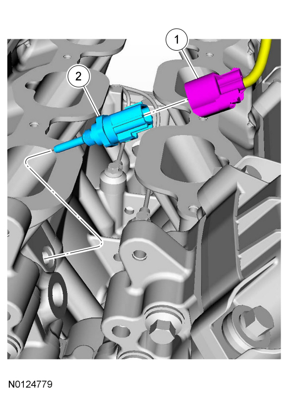
Repair Removal and Replacement Cylinder Head Temperature (CHT) Sensor - 3.5L Ti-VCT, Exploded View
pic 12
Item Service Part Number Description Tool Number Material Name Notes
1 - CHT sensor electrical connector (part of 12A581) - - -
2 6G004 CHT sensor - - 10 Nm (89 lb-in)
Removal
WARNING: Before beginning any service procedure in this section, refer to Safety Warnings in Section 100-00 . Failure to follow this instruction may result in serious personal injury.
Remove the lower intake manifold. For 3.5L Twin Independent Variable Cam Timing (Ti-VCT) engine, REFER to Section 303-01B, Lower Intake Manifold . For 3.7L Twin Independent Variable Cam Timing (Ti-VCT) engine, .
Disconnect the CHT sensor electrical connector.
Remove and discard the CHT sensor.
Installation
NOTE: Do not reuse the CHT sensor. Install a new sensor.
Install a new CHT sensor.
Tighten to 10 Nm (89 lb-in).
Connect the CHT sensor electrical connector.
Install the lower intake manifold. For 3.5L Twin Independent Variable Cam Timing (Ti-VCT) engine, REFER to Section 303-01B, Lower Intake Manifold . For 3.7L Twin Independent Variable Cam Timing (Ti-VCT) engine,
________________________________
2015 Ford Truck Explorer 4WD V6-3.5L
Lower Intake Manifold
REMOVAL AND INSTALLATION
Removal
NOTICE: During engine repair procedures, cleanliness is extremely important. Any foreign material, including any material created while cleaning gasket surfaces that enters the oil passages, coolant passages or the oil pan, can cause engine failure.
With the vehicle in NEUTRAL, position it on a hoist. REFER to Section 100-02, Jacking and Lifting, Lifting Points.
Release the fuel system pressure. REFER to Section 310-00, Fuel System Pressure Release .
Disconnect the battery ground cable. REFER to Section 414-01, Battery Disconnect .
Drain the cooling system. REFER to Section 303-03, Cooling System Draining, Filling and Bleeding .
Remove the upper intake manifold. Refer to Upper Intake Manifold .
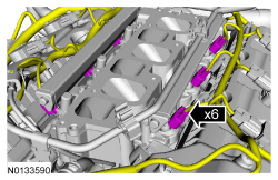
Disconnect the 6 fuel injector electrical connectors.
pic 13
Disconnect the fuel supply tube-to-fuel rail quick connect coupling. REFER to Section 310-00, Quick Connect Coupling . Position fuel supply tube aside.
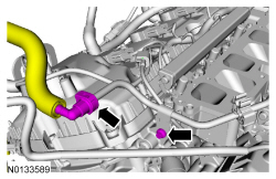
Remove the bolt from the fuel supply tube-to-rail bracket.
pic 14
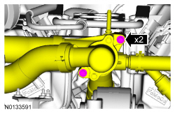
Remove the 2 thermostat housing-to-lower intake manifold bolts.
pic 15
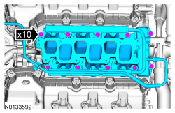
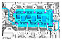
Remove the 10 bolts and the lower intake manifold.
Remove and discard the intake manifold and thermostat housing gaskets.
Clean and inspect all sealing surfaces.
pic 16
Installation
NOTICE: If the engine is repaired or replaced because of upper engine failure, typically including valve or piston damage, check the intake manifold for metal debris. If metal debris is found, install a new intake manifold. Failure to follow these instructions can result in engine damage.
Using new intake manifold and thermostat housing gaskets, install the lower intake manifold and the 10 bolts.
Tighten in the sequence shown to 10 Nm (89 lb-in).
pic 17
Install the 2 thermostat housing-to-lower intake manifold bolts.
Tighten to 10 Nm (89 lb-in).
pic 18
Connect the fuel supply tube-to-fuel rail quick connect coupling. REFER to Section 310-00, Quick Connect Coupling .
Install the bolt to the fuel supply tube-to-rail bracket and tighten to 10 Nm (89 lb-in).
pic 19
Connect the 6 fuel injector electrical connectors.
pic 20
Install the upper intake manifold. Refer to Upper Intake Manifold .
Connect the battery ground cable. REFER to Section 414-01, Battery Disconnect .
Fill and bleed the cooling system. REFER to Section 303-03, Cooling System Draining, Filling and Bleeding .
__________________________
I hope this helps. Let me know if you have other questions.
Take care,
Joe
Images (Click to enlarge)
Oct 28, 2020 at 5:56 PM