TEST A: POWER DOOR LOCKS INOPERATIVE (ALL DOORS & SWITCHES)
If door systems diagnostic system check has been performed, go to next step. If door systems diagnostic system check has not been performed, go to DOORS DIAGNOSTIC SYSTEM CHECK under SELF-DIAGNOSTIC SYSTEM.
Verify power door locks inoperative fault exists (all doors and switches). If fault exists, go to next step. If power door lock system operates properly, fault may be intermittent. Check for intermittent and poor connections. Go to DIAGNOSING INTERMITTENTS in BODY CONTROL MODULES - MONTANA, SILHOUETTE & VENTURE article.
Check PWR LOCK fuse (20-amp) in instrument panel fuse block, located behind right side instrument panel endcap. If fuse is blown, go to next step. If fuse is okay, go to step 5.
Check for short to ground in Orange wire between PWR LOCK fuse and BCM harness connector C1 terminal "H". See Fig. 6. If Orange wire is okay, go to step 6. If Orange wire is not okay, repair as necessary. After repair, go to step 13.
Check for an open in Orange wire between PWR LOCK fuse and BCM harness connector C1 terminal "H". See Fig. 6. If Orange wire is okay, go to step 7. If Orange wire is not okay, repair as necessary. After repair, go to step 13.
Check for short to ground in suspect door lock actuator lock control circuits. If all circuits are okay, go to step 8. If any circuit is not okay, repair as necessary. After repair, go to step 13.
Check for an open in suspect door lock actuator control circuits (Tan or Gray wires) between BCM and door lock actuators and/or door lock switches. If all circuits are okay, go to step 9. If any circuit is not okay, repair as necessary. After repair, go to step 13.
Check for short to ground in suspect door lock actuator unlock control circuits. If circuit(s) are okay, go to step 10. If circuit(s) are not okay, repair as necessary. After repair, go to step 13.
Check for short to ground in suspect door lock actuator lock control circuit. If circuit(s) are okay, go to step 10. If circuit(s) are not okay, repair as necessary. After repair, go to step 13.
Check for short to ground in Tan wire between BCM harness connector C1 terminal "A" and driver's door lock actuator harness connector C2 terminal "A". If Tan wire is okay, go to next step. If Tan wire is not okay, repair as necessary. After repair, go to step 13.
Check BCM harness connectors for damage and intermittent or poor terminal contact. If connectors and terminal contact are okay, go to next step. If connectors and terminal contact is not okay, repair as necessary. After repair, go to step 13.
Replace BCM. See BODY CONTROL MODULE under REMOVAL & INSTALLATION. After repair, go to next step.
Operate system to verify repair. If fault still exists, go to step 2.
TEST C: FRONT WIPERS INOPERATIVE IN ONE OR MORE MODES
If description and operation has been reviewed, go to next step. If description and operation has not been reviewed, go to DESCRIPTION & OPERATION.
Turn ignition switch to RUN position. Turn multifunction switch through all switch positions. If front wipers do not operate normally in all modes, go to next step. If front wipers operate normally in all modes, diagnose intermittent condition. See DIAGNOSING INTERMITTENTS in BODY CONTROL MODULES - MONTANA, SILHOUETTE & VENTURE article.
Turn ignition switch to LOCK position. Disconnect multifunction switch 48-pin harness connector C201. Harness connector C201 is located to left side of steering column, near base. Disconnect front wiper motor 6-pin harness connector. Check for open, high resistance or short to ground in Purple wire between front wiper motor and multifunction switch. See WIRING DIAGRAMS. If problem does not exist, go to next step. If problem exists, repair as necessary. After repair, go to step 13.
Check for open, high resistance or short to ground in Gray wire between front wiper motor and multifunction switch. See WIRING DIAGRAMS. If problem does not exist, go to next step. If problem exists, repair as necessary. After repair, go to step 13.
Check for open, high resistance or short to ground in Dark Green wire between front wiper motor and multifunction switch. See Fig. 2 and Fig. 3 and WIRING DIAGRAMS. If problem does not exist, go to next step. If problem exists, repair as necessary. After repair, go to step 13.
Measure resistance between multifunction switch pigtail harness connector C201 terminals E3 (Dark Green wire) and E9 (Yellow wire) - (component side). See Fig. 3. Turn wiper portion of multifunction switch to MIST, LO and HI positions. If resistance is less than 2 ohms, go to next step. If resistance is 2 ohms or more, go to step 10.
Measure resistance between multifunction switch pigtail harness connector C201 terminals E3 (Dark Green wire) and E9 (Yellow wire) - (component side). Turn multifunction switch through all DELAY positions. Resistance should be 39-680 k/ohms. If resistance is as specified, go to next step. If resistance is not as specified, go to step 10.
Measure resistance between multifunction switch pigtail harness connector C201 terminals E3 (Dark Green wire) and E9 (Yellow wire) - (component side). Turn wiper portion of multifunction switch to MIST, LO and HI positions. Resistance should be 24 k/ohms. If resistance is as specified, go to next step. If resistance is not as specified, go to step 10.
Connect multifunction switch harness connector C201. Connect front wiper/washer motor harness connector. Turn ignition switch to RUN position. Turn wiper portion of multifunction switch to HI position. If front wipers operate normally, go to step 11. If front wipers do not operate normally, go to step 12.
Replace multifunction switch. See REMOVAL & INSTALLATION. After repair, go to step 13.
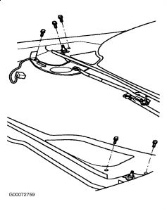
Replace front wiper drive system module. See REMOVAL & INSTALLATION. After repair, go to step 13.
Replace front wiper motor. See REMOVAL & INSTALLATION. After repair, go to next step.
Operate system to verify repair. If problem does not exist, system is okay. If problem still exists, go to step 3.
Thursday, March 25th, 2010 AT 5:55 PM