89 Chevy Cavaliar

Tiny
JAMESAJONES
  • MEMBER
  • 1989 CHEVROLET TRUCK
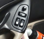
I have an 89 Chevy Cavaliar that I'm trying to fix the power window (Driver Side) switch. I need the layout for the wire setup in the switch. I know where the ground goes but I have no Idea where the rest of them are suppose to sit at on the switch. If someone has a pick of the back of the switch that would be helpful.
Saturday, July 15th, 2006 AT 4:56 PM

5 Replies

Tiny
MIKEYBDMAN
  • MECHANIC
  • 623 POSTS
You got a counsole, or not? You just want to know which wires go to what pins?
2 doors or 4?
Convertible or not?
Was this
answer
helpful?
Yes
No
Saturday, July 15th, 2006 AT 5:16 PM
Tiny
JAMESAJONES
  • MEMBER
  • 3 POSTS
Its a 2 door. No console. Yeah just what wires goes to which pin.
Was this
answer
helpful?
Yes
No
Saturday, July 15th, 2006 AT 7:06 PM
Tiny
MIKEYBDMAN
  • MECHANIC
  • 623 POSTS
Ok, your driver side switch should have the following wires attached:
Pin F: Pnk (Power)
Pin E: Blu/Wht (RH Front Up)
Pin D: Tan (RH Front Down)
Pin C: Dk Blu (LH Front Up)
Pin B: Brn (LH Front Down)
Pin A: Blk (Ground)
Hope this works and you get it set up correctly. You can always test the circuits with jumpers. But remember when you are driving the motor you must jump Pin A to the opposite wire for the window you are driving.
Example: You want to drive the left front window down. Jumper pin A to pin E to supply the ground return path for the motor, and then jumper pin F to pin D to supply power to run the motor.
Was this
answer
helpful?
Yes
No
Saturday, July 15th, 2006 AT 8:06 PM
Tiny
JAMESAJONES
  • MEMBER
  • 3 POSTS
The pins are not marked and I have no Idea which ones they are. Execpt for the ground.
Was this
answer
helpful?
Yes
No
Saturday, July 15th, 2006 AT 9:45 PM
Tiny
MIKEYBDMAN
  • MECHANIC
  • 623 POSTS
Wow, this will be a little more difficult. But do-able.
First, you need to find the ground and power terminals. I suggest drawing an image to keep your self straight.
With an ohm meter, check the pins on the switch for continuity. With all of the switches not pressed, the power terminal will not have continuity with any other pin. Mark this terminal F, and it should connect to the pink wire.
Now, press the RH Front Up switch and hold. Check from pin F to the other terminal that now has continuity. This is Pin E, and should connect to the Blu/Wht wire.
Press the RH Front Dn switch and hold. Check from pin F to the terminal that now has continuity and this is pin D. It should connect to the Tan wire.
Press the LH Up switch and hold. Check from the pin F to the terminal that now has continuity and this should be pin C. Connect the Dk Blu wire to this one.
Press the LH Dn switch and hold. Check from pin F to the terminal that now has continuity and this should be pin B/ Connect the Brn wire to that.
The ground is the terminal that has continuity with pin E, pin D, Pin C, and pin B with no switches pressed.
Hope this works for you.
Was this
answer
helpful?
Yes
No
Sunday, July 16th, 2006 AT 3:04 PM

Please login or register to post a reply.

Sponsored links