1999 Chevy Suburban Oxygen sensor and evaporative purge sol

Tiny
TECLIETT
  • MEMBER
  • 1999 CHEVROLET SUBURBAN
  • V8
  • 2WD
  • AUTOMATIC
  • 156,000 MILES
Can you tell me where both of these are located and how to replace them? Both are supposedly bad and are causing to fail the inspection test. Thank you.
Saturday, August 29th, 2009 AT 1:20 PM

33 Replies

Tiny
MXCANICHOLS
  • MEMBER
  • 3 POSTS
Which oxygen sensor? There are 4 Heated o2 sensors on the exhaust pipe. Bank 1 sensor 1 left side just below exh manifold to pipe connection, bank 2 sensor 1 r side same location, Bank 2 sensor 2 r side just aft of catalytic converter, bank 1 sensor 2 same location on left side.
The Heated Oxygen Sensors are mounted in the exhaust system where they can monitor the oxygen content of the exhaust gas stream. The oxygen present in the exhaust gas reacts with the sensor to produce a voltage output. This voltage should constantly fluctuate from approximately 100 mV (high oxygen content - lean mixture) to 900 mV (low oxygen content - rich mixture). The heated oxygen sensor voltage can be monitored with a scan tool. By monitoring the voltage output of the oxygen sensor, the PCM calculates what fuel mixture command to give to the injectors (lean mixture - low HO2S voltage = rich command, rich mixture - high HO2S voltage = lean command).
When the VCM detects a malfunction in the HO2S heater circuits, the following DTCs will set:
"Â DTC P0135 Bank 1 Sensor 1 heater.
"Â DTC P0155 Bank 2 Sensor 1 heater.
"Â DTC P0141 Bank 1 Sensor 2 heater.
"Â DTC P0161 Bank 2 Sensor 2 heater.
When the VCM detects no HO2S activity, the VCM will set the following DTCs:
"Â DTC P0134 Bank 1 Sensor 1.
"Â DTC P0154 Bank 2 Sensor 1.
"Â DTC P0140 Bank 1 Sensor 2.
"Â DTC P0160 Bank 2 Sensor 2.
When the VCM detects an HO2S signal circuit that is high, the VCM will set the following DTCs:
DTC P0132 Bank 1 Sensor 1.
"Â DTC P0152 Bank 2 Sensor 1.
"Â DTC P0138 Bank 1 Sensor 2.
"Â DTC P0158 Bank 2 Sensor 2.
When the VCM detects an HO2S signal circuit that is low, the VCM will set the following DTCs:
"Â DTC P0131 Bank 1 Sensor 1.
"Â DTC P0151 Bank 2 Sensor 1.
"Â DTC P0137 Bank 1 Sensor 2.
"Â DTC P0157 Bank 2 Sensor 2.


https://www.2carpros.com/forum/automotive_pictures/404531_Heated_o2_sensor_1.jpg


CAUTION : The Heated Oxygen Sensor (HO2S) and the Oxygen Sensor use a permanently attached pigtail and connector. Do not remove this pigtail from the Heated Oxygen Sensor. Damage or the removal of the pigtail or the connector could affect the proper operation of the sensor.

CAUTION : Take care when handling the HO2S. Keep the in-line electrical connector and the louvered end free of grease, dirt, or other contaminants. Also avoid using cleaning solvents of any type. Do not drop or roughly handle the HO2S.

CAUTION : If the heated oxygen sensor pigtail wiring, connector or terminal is damaged, the entire oxygen sensor assembly must be replaced. Do Not attempt to repair the wiring, connector or terminals. In order for the sensor to function properly, it must have provided to it a clean air reference.

CAUTION : This clean air reference is obtained by way of the oxygen sensor signal and heater wires. Any attempt to repair the wires, connectors, or terminals could result in the obstruction of the air reference and degraded sensor performance. The following guidelines should be used when servicing the heated oxygen sensor:

"Â Do Not apply contact cleaner or other materials to the sensor or vehicle harness connectors. These materials may get into the sensor causing poor performance.
"Â The sensor pigtail and harness wires must not be damaged in such a way that the wires inside are exposed. This could provide a path for foreign materials to enter the sensor and cause performance problems,
"Â Neither the sensor or vehicle lead wires should be bent sharply or kinked. Sharp bends, kinks, etc., could block the reference air path through the lead wire.
"Â Do Not remove or defeat the oxygen sensor ground wire (where applicable). Vehicles that utilize the ground wired sensor may rely on this ground as the only ground contact to the sensor. Removal of the ground wire will cause poor engine performance.
"Â To prevent damage due to water intrusion. be sure that the peripheral seal remains intact on the vehicle harness connector. The engine harness may be repaired using Packard's Crimp and Splice Seals Terminal Repair Kit. Under no circumstances should repairs be soldered since this could result in the air reference being obstructed.
CAUTION : The Heated Oxygen Sensor (HO2S) may be difficult to remove when the engine temperature is below 48 °C (120 °F). Excessive force may damage the threads in the exhaust manifold or the exhaust pipe.

REMOVAL PROCEDURE

1.Disconnect the negative battery cable.
2.Remove the electrical connector by releasing the locking tab.
3.Carefully back out the heated oxygen sensor.
INSTALLATION PROCEDURE

NOTE : A special anti-seize compound is used on the Heated Oxygen Sensor (HO2S) threads. The compound consists of liquid graphite and glass beads. The graphite tends to burn away, but the glass beads remain, making the sensor easier to remove. New, or service replacement sensors already have the compound applied to the threads. If the sensor is removed from an engine and if for any reason it is to be reinstalled, the threads must have anti-seize compound applied before the reinstallation.

1.Coat the threads of the oxygen sensor with anti-seize compound GM P/N 5613695 or the equivalent if necessary.
2.Install the sensor. Tighten
"Â Tighten the sensor to 41 Nm (30 lb. ft.) .
3.Install the electrical connector.
4.Connect the negative battery cable.
Was this
answer
helpful?
Yes
No
+6
Thursday, September 3rd, 2009 AT 9:45 AM
Tiny
MXCANICHOLS
  • MEMBER
  • 3 POSTS
Loaction on r side of intake manifold looking forward, just forward of igniton coil area. Look for black plastic hose connecting to it. Two vertical mounting bolts. I believe 10mm. One electrical plug on top. Disconect plug, remove nut from mounting stud, disconnect hose, lift out of intake manifold.


https://www.2carpros.com/forum/automotive_pictures/404531_Evap_sol_1.jpg

Was this
answer
helpful?
Yes
No
+7
Thursday, September 3rd, 2009 AT 9:59 AM
Tiny
JESSICA BENTON
  • MEMBER
  • 1 POST
  • 1999 CHEVROLET SUBURBAN
  • 5.7L
  • V8
  • 4WD
  • AUTOMATIC
  • 200,000 MILES
Looking for the location of all the O2 sensors and where they plug into.
Was this
answer
helpful?
Yes
No
+1
Thursday, February 7th, 2019 AT 7:23 PM (Merged)
Tiny
ASEMASTER6371
  • MECHANIC
  • 52,797 POSTS
Good evening,

I attached a picture of the location of the sensors. The connectors are usually within about a foot of the sensor

What is your exact issue as these do not fail that often?

Roy
Was this
answer
helpful?
Yes
No
-1
Thursday, February 7th, 2019 AT 7:23 PM (Merged)
Tiny
DALEFIN
  • MEMBER
  • 1 POST
  • 1999 CHEVROLET SUBURBAN
  • V8
  • 4WD
  • AUTOMATIC
  • 107,000 MILES
Where is o2 sensor bank1 sensor1 located?
Was this
answer
helpful?
Yes
No
Thursday, February 7th, 2019 AT 7:23 PM (Merged)
Tiny
BLACKOP555
  • MECHANIC
  • 10,371 POSTS
Driver side exhaust BEFORE the catalytic convertor.

Try running the engine till its hot before removing it, dont get burned.
Was this
answer
helpful?
Yes
No
Thursday, February 7th, 2019 AT 7:23 PM (Merged)
Tiny
CBCROCKER
  • MEMBER
  • 4 POSTS
  • 1999 CHEVROLET SUBURBAN
  • V8
  • 2WD
  • AUTOMATIC
  • 173,000 MILES
I just got the P0430 code and have been reading up on it. The first thing they say to do is check the voltage at the O2 sensors. No problem with that but I can't find anything stating what the readings should be. Also, is there a way to tell if it's the pre-cat or post-cat sensors?
Was this
answer
helpful?
Yes
No
+1
Thursday, February 7th, 2019 AT 7:23 PM (Merged)
Tiny
DOCFIXIT
  • MECHANIC
  • 18,828 POSTS
Bank 1 past CAT voltage.02-1V at idle. Lean.1v rich.9V
Was this
answer
helpful?
Yes
No
-2
Thursday, February 7th, 2019 AT 7:23 PM (Merged)
Tiny
YOLIE0622
  • MEMBER
  • 3 POSTS
  • 1999 CHEVROLET SUBURBAN
  • V8
  • 4WD
  • AUTOMATIC
  • 138,000 MILES
Check engine light is on. Used my OBD2 meter & codes 140 & 137 came up. I changed all sensors, cat convert, transmission, & transfer case has been recently changed. Check engine still on. There was a wire lose going to the oxygen sensors & I had it repaired. Check engine light still on with the same codes. What else can it be?
Was this
answer
helpful?
Yes
No
Thursday, February 7th, 2019 AT 7:23 PM (Merged)
Tiny
KHLOW2008
  • MECHANIC
  • 41,815 POSTS
Hi yolie0622,

thank you for the donation.

Is your vehicle a C or K body model?
Was this
answer
helpful?
Yes
No
Thursday, February 7th, 2019 AT 7:23 PM (Merged)
Tiny
YOLIE0622
  • MEMBER
  • 3 POSTS
K1500, 8cyl.
Was this
answer
helpful?
Yes
No
+1
Thursday, February 7th, 2019 AT 7:23 PM (Merged)
Tiny
KHLOW2008
  • MECHANIC
  • 41,815 POSTS
If after replacement of sensors and the problem recurrs, the next thing to do would be to check the wirings. Here are the diagnostic procedures.

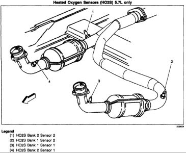
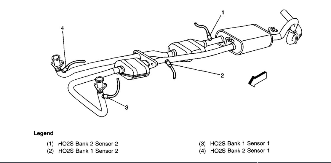
DTC P0137: HO2S CIRCUIT-LOW VOLTAGE-BANK 1, SENSOR 2 (4.8L, 5.3L & 6.0L "C" & "K" SERIES & 5.7L "F" & "Y" BODIES)

Circuit Description
PCM supplies about 450 millivolts (mV) between HO2S high and low signal circuits. The HO2S voltage ranges from about 1000 mV when exhaust is rich to about 10 mV when exhaust is lean. PCM monitors and stores sensor voltage information and evaluates voltage samples to determine amount of time sensor voltage is out of range. If PCM detects HO2S voltage is less than predetermined voltage, DTC P0137 will set.

For duplication of DTC, ensure:

"Â DTCs P0101, P0102, P0103, P0112, P0113, P0117, P0118, P0121, P0122, P0123, P0125, P0200, P0335, P0336, P0351-P0358 or P1258 are not set.
"Â AIR, EGR and catalyst diagnostics not active.
"Â Ignition voltage is greater than 9 volts.
"Â Fuel system is operating in "closed loop".
"Â Fuel trim learn is enabled.
"Â TP sensor angle is between 2 and 70 percent.

Diagnostic Procedures

1. Perform On-Board Diagnostic (OBD) system check.
After performing OBD system check, go to next
step.
2. Start and warm engine to normal operating temperature. Operate vehicle under conditions equired to set DTC. Using scan tool, select ENGINE 1 DATA LIST and monitor HO2S voltage. If HO2S 2 voltage is fixed less than 80 mV, go to step 4. If HO2S voltage is not fixed less than 80 mV, go to next step.

3. Turn ignition on, with engine off. Using scan tool, review FREEZE FRAME and/or FAILURE RECORDS data and note parameters. Turn ignition off for about 15 seconds. Start engine and operate vehicle within conditions required for this diagnostic to run, and as
close to conditions recorded in FREEZE FRAME/FAILURE RECORDS as possible. Select DTC function, and then enter DTC P0137. If scan tool indicates that this test failed this ignition, go to next step. If scan tool does not indicate that this test failed this ignition, see DIAGNOSTIC AIDS.

4. Disconnect HO2S 2 connector. Connect a fused jumper wire between PCM connector (harness side), HO2S 2 low circuit and ground. If sensor voltage is 350-550 mV, see DIAGNOSTIC AIDS. If sensor voltage is not 350-550 mV, go to next step.

5. Turn ignition off. Disconnect PCM harness connector C1. Check HO2S 2 signal circuit for short to ground or short to sensor ground circuit. Repair as necessary. After repairs, go to next step. If circuit(s) are okay, go to step 7.

6. Repair HO2S 2 signal circuit. After repairs, go to step 8.

7. Replace PCM. Program replacement PCM using required equipment. After repairs, go to next step.

8. Using scan tool, clear DTCs. Start and warm engine to normal operating temperature. Select
DTC, SPECIFIC, and then enter DTC P0137. Operate vehicle within conditions for setting this DTC. If scan tool indicates that this test ran and passed, go to next step. If scan tool does not indicate that this test ran and passed, go to step 2.

9. Using scan tool, select CAPTURE INFO, REVIEW INFO function. If any undiagnosed DTCs are displayed, go to applicable DTC test. If no undiagnosed DTCs are displayed, system is okay.

Diagnostic Aids
Check HO2S pigtail wire for breaks, contamination or grounding on exhaust manifold. Check for intermittent ground in signal wire between sensor connector and sensor.

Check for lean injector(s). Perform injector balance test. See appropriate SYSTEM & COMPONENT TESTING article. Check for fuel contamination, improper fuel pressure or exhaust leak, especially near HO2S. Check for vacuum or crankcase leak, causing a lean condition.

DTC P0140: HO2S CIRCUIT-INSUFFICIENT ACTIVITY-BANK 1, SENSOR 2 (4.3L, 5.0L, 5.7L & 7.4L "C", "G", "K" & "P" SERIES)

Circuit Description
VCM supplies a voltage of about.45 volt between HO2S 2 signal and HO2S 2 ground circuits. HO2S 2 varies voltage from about one volt with rich exhaust to.1 volt with lean exhaust. HO2S 2 produces no voltage and acts as an open circuit when temperature is less than 600 °F (316 °C). An open sensor circuit or a cold sensor causes open loop operation.

HO2S 2 heater provides for faster sensor warm-up allowing sensor to become active in a shorter period of time and remain active during long extended idle. DTC determines if HO2S 2 or HO2S 2 circuit is open. DTC P0140 will set if VCM fails to detect minimum number of HO2S 2 voltage transitions greater than and less than bias voltage range of 300-600 mV.

For duplication of DTC, ensure:

"Â No active EVAP system, misfire, TP, IAT, MAP, ECT or MAF sensor DTCs are set.
"Â No intrusive tests are in progress.
"Â No device controls are active.
"Â System voltage is 11.7-18 volts.
"Â Engine run time is greater than 2 minutes.
"Â Decel fuel cut-off mode is not active.
" ECT is 137 °F (58.5 °C) or greater.
"Â MAF is 13 grams per second.
"Â System is in closed loop.

Diagnostic Procedures

1. Perform On-Board Diagnostic (OBD) system check. After performing OBD system check, go to next
step.

2. Using scan tool, store DTC information from VCM. Clear DTCs and reset fuel trim values. Start engine and allow it to reach normal operating temperature. Monitor HO2S 2 voltage on scan tool. If voltage is fixed at 400-473 mV, go to step 4. If voltage is not as specified, go to next step.

3. Condition that set DTC is not present at this time. If any additional DTCs are set, go to applicable DTC test. If no additional DTCs are set, see DIAGNOSTIC AIDS.

4. Turn ignition off. Disconnect HO2S 2 harness connector. Using jumper wires, jumper HO2S 2 high and low signal circuits to ground. Turn ignition on. Monitor HO2S 2 voltage with scan tool. If voltage is less than 20 mV, go to step 7. If voltage is not less than 20 mV, go to next step.

5. Turn ignition off. Remove jumper wires. Disconnect VCM harness connector containing HO2S 2 circuits. Measure resistance of HO2S 2 high and low signal circuits between HO2S 2 and VCM. If resistance of both circuits is less than 5 ohms, go to next step. If resistance of either circuit is not less than 5 ohms, go to step 9.

6. Check VCM harness connections. Repair as necessary. After repairs, go to step 17. If connections are okay, go to step 16.

7. Remove jumper wires from HO2S 2. Turn ignition on. Connect test light between HO2S 2 heater ignition feed and ground circuits at HO2S 2 harness connector. If test light illuminates, go to next step. If test light does not illuminate, go to step 10.

8. Turn ignition off. Reconnect HO2S 2 harness connector. Disconnect VCM harness connector containing HO2S 2 low signal circuit and VCM harness connector containing VCM ground circuits. Measure resistance between HO2S 2 low signal circuit and one of the VCM ground circuit terminals at VCM harness connector. If resistance is less than 500
ohms, go to step 12. If resistance is not less than 500 ohms, go to step 11.

9. Repair circuit with high resistance. After repairs, go to step 17.

10. Repair HO2S 2 heater ignition feed or ground circuit. After repairs, go to step 17.

11. Repair high resistance between HO2S 2 low signal circuit and VCM ground circuit. After repairs, go to step 17.

12. Check for exhaust leaks upstream of HO2S 2. Repair as necessary. After repairs, go to step 17. If no leaks are found, go to next step.

13. Allow engine to completely cool. Measure resistance between HO2S 2 low signal circuit and one of the VCM ground circuit terminals at VCM harness connector. If resistance is less than 500 ohms, go to step 15. If resistance is not less than 500 ohms, go to next step.

14. Remove HO2S 2. Clean threads and apply anti-seize compound, and then reinstall. Measure resistance between HO2S 2 low signal circuit and one of the VCM ground circuit terminals at VCM harness connector. If resistance is less than 500 ohms, go to step 17. If resistance is not less than 500 ohms, go to next step.

15. Replace HO2S 2. After repairs, go to step 17.

16. Replace VCM. Program replacement VCM using required equipment. Perform Passlock  reprogramming and CKP system variation learn procedures. After repairs, go to next step.

17. Using scan tool, clear DTCs. Start engine and operate vehicle under conditions required to set this DTC. If scan tool indicates this test ran and passed, go to next step. If scan tool does not indicate this test ran and passed, go to step 2.

18. Using scan tool, select CAPTURE INFO, REVIEW INFO function. If any undiagnosed DTCs are displayed, go to applicable DTC test. If no undiagnosed DTCs are displayed, system is okay.

Diagnostic Aids
An intermittent may be caused by a poor connection, rubbed-through wire insulation or a broken wire inside insulation. Inspect harness connectors for backed-out terminals, improper mating, broken locks, improperly formed or damaged terminals, poor terminal-to-wire connection, and
damaged harness.

With ignition on and engine off, HO2S 2 voltage on scan tool should gradually decrease to less than.15 volt indicating heater is operating properly. If voltage does not decrease as specified, disconnect HO2S 2 connector and connect a test light between HO2S 2 connector terminals "C" and "D" (engine harness side). If test light illuminates, replace HO2S 2. If test light does not illuminate, repair open in HO2S 2 heater ground circuit or HO2S 2 ignition feed circuit.
Using scan tool, monitor signal voltage while wiggling O2S 2 related connectors and wiring harness with a warm engine running at part throttle in closed loop. If a failure is induced, signal voltage will change from normal fluctuating voltage of greater than.6 volt and less than.3 volt, to a fixed voltage of about.45 volt. A change in voltage will assist in isolating location of fault. DO NOT solder HO2S wires.
Was this
answer
helpful?
Yes
No
Thursday, February 7th, 2019 AT 7:23 PM (Merged)
Tiny
ROTORY-POWER
  • MEMBER
  • 9 POSTS
  • 1999 CHEVROLET SUBURBAN
I have a 1999 Chevy Suburban K1500 5.7L with 173000 miles. I just replaced the starter & ignition switch. Got it running again, but am now showing a check engine light. On a couple of starts since installing the ignition switch the security light has also come on and stayed on, but it didn't affect the drivability. The truck hasn't been driven in the past 3 years and I can't remember if the check engine light was on or not before I stopped using it. I took it to AutoZone and had them pull the codes for it, but they couldn't tell me much beyond that. I also took it to the dealer and they wouldn't tell me anything except "$92 for an emissions diognostic", even though I had the codes in my hand. The codes that came up are as follows:

P0135 - HO2S 11 Heater Condition (Heated Oxygen Sensor Bank 1 Sensor 1)

P0155 - HO2S 21 Heater Condition (Heated Oxygen Sensor Bank 2 Sensor 1)

P0141 - HO2S 12 Heater Condition (Heated Oxygen Sensor Bank 1 Sensor 2)

P0161 - HO2S 22 Heater Condition (Heated Oxygen Sensor Bank 2 Sensor 2)

What is most likely to cause this problem?
-Bad O2 Sensors?
-Bad Cat?
-Electrical/PCM Problems?

Just wondering where I should start and how to test? Thanks in advance for your time.
Was this
answer
helpful?
Yes
No
Thursday, February 7th, 2019 AT 7:23 PM (Merged)
Tiny
MXCANICHOLS
  • MEMBER
  • 3 POSTS
It is highly unlikely that all four sensors are bad. It is more likely that the fuse is blown. There is a 20amp fuse in the under hood fuse box. It is located along the drivers side fender aft in the underhood area. It should be labeled something like "Eng 1" If thats not blown, Check the grounding point on the lower front right side of the motor next to the harmonic balancer. There sould be a black battery type cable there. Those are the only two item that affect all 4 sensors other than the VCM- vehicle control module itself, but if that was failed, you would probably have other problems too
Was this
answer
helpful?
Yes
No
+1
Thursday, February 7th, 2019 AT 7:23 PM (Merged)
Tiny
BIGTIMETRUCK
  • MEMBER
  • 9 POSTS
  • 2000 CHEVROLET SUBURBAN
  • V8
  • 4WD
  • AUTOMATIC
  • 83,000 MILES
My check engine light is on, a diagnostic test states to replace Oxgen sensor 1 & 2 on both banks, as preventive maintenance I changed pre & Post cat on Both Banks, now the computer gave me multiple other codes, after installation.
Was this
answer
helpful?
Yes
No
Thursday, February 7th, 2019 AT 7:23 PM (Merged)
Tiny
JACOBANDNICKOLAS
  • MECHANIC
  • 108,133 POSTS
Were the O2 sensors replaced or only the cats? Also, are the codes reflecting the O2 sensors again?
Was this
answer
helpful?
Yes
No
Thursday, February 7th, 2019 AT 7:23 PM (Merged)
Tiny
BIGTIMETRUCK
  • MEMBER
  • 9 POSTS
I replaced all 4 oxgen sensors, the I got all of these codes and I am lost.
P0300
P0154
P0155
P0161
P1153
P1336

any advice
Was this
answer
helpful?
Yes
No
Thursday, February 7th, 2019 AT 7:23 PM (Merged)
Tiny
JACOBANDNICKOLAS
  • MECHANIC
  • 108,133 POSTS
The 1336 is my concern. Basically, it means the crankshaft position system variation values have not been stored in the PCM and the crankshaft position system variation learn procedure must be performed. That could be throwing off the sensors.

I can't be 100% sure, but I feel there is a problem with the PCM. You need to have a dealer check it.
Was this
answer
helpful?
Yes
No
Thursday, February 7th, 2019 AT 7:23 PM (Merged)
Tiny
BIGTIMETRUCK
  • MEMBER
  • 9 POSTS
Is the PCM the Same as the ECM(computer)? I just want to make sure. I am reading you, correctly. And where is the Crank Postion Sensor located.
Was this
answer
helpful?
Yes
No
Thursday, February 7th, 2019 AT 7:23 PM (Merged)
Tiny
JACOBANDNICKOLAS
  • MECHANIC
  • 108,133 POSTS
Yes
Was this
answer
helpful?
Yes
No
Thursday, February 7th, 2019 AT 7:23 PM (Merged)

Please login or register to post a reply.

Sponsored links