Its not looking good
this is what I have on this code
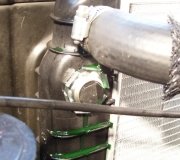
check wiring
disconnect ABS unit wiring harness and check for corrosion and or moisture
check the pins inside the connector
ANTILOCK BRAKE SYSTEM -2003 Chevrolet Impala
DTC C1218
Circuit Description
The system relay is energized when the ignition is ON. The system relay supplies voltage to the solenoid valves and the pump motor. This voltage is referred to as the system voltage.
The electronic brake control module (EBCM) controls each solenoid valve by grounding the solenoid.
The EBCM controls the pump motor by grounding the control circuit. The pump serves 2 purposes:
Transfers brake fluid from the brake calipers to the master cylinder reservoir during pressure decrease events.
Transfers brake fluid from the master cylinder reservoir to the brake calipers during pressure increase events.
Conditions for Running the DTC
The pump motor is commanded ON.
The system voltage is greater than 8 volts.
Conditions for Setting the DTC
One of the following conditions exists for 0.16 seconds:
With the commanded pump motor voltage less than the system voltage, the actual pump motor voltage is 3 volts less than the commanded voltage.
? With the commanded pump motor voltage greater than the system voltage, the actual pump motor voltage is less than 8 volts.
Action Taken When the DTC Sets
If equipped, the following actions occur:
? The EBCM disables the ABS/TCS for the duration of the ignition cycle.
? The DRP does not function optimally.
? The ABS indicator turns ON.
? The Traction Off indicator turns ON.
? The message center displays the Service Traction System message.
Conditions for Clearing the DTC
? The condition for the DTC is no longer present and the DTC is cleared with a scan tool.
? The electronic brake control module (EBCM) automatically clears the history DTC when a
current DTC is not detected in 100 consecutive drive cycles.
Diagnostic Aids
The pump motor is integral to the BPMV. The pump motor is not serviceable.
Test Description
The number below refers to the step number on the diagnostic table.
5: Tests the ability of the EBCM to control the pump motor. If the test lamp illuminates, the pump motor circuit within the EBCM is good.
DTC C1218
Step Action Yes No
Schematic Reference: ABS Schematics Did you perform the ABS Diagnostic System Check? Go to Step 2 ABS 1. Use the scan tool in order to clear the DTCs. 2. With the scan tool, perform the Automated Test. 1 2 Go to Testing for Intermittent Conditions and Go to Diagnostic System Check -
Does the DTC reset? 1. Remove the EBCM from the BPMV. Refer to Electronic Brake Control Module Replacement. 2. Inspect the EBCM to BPMV connector for conditions which could cause an intermittent, such as damage, corrosion, poor terminal contact, or presence of brake fluid.
Go to Step 3
Poor Connections in Wiring Systems
3
4
Is connector OK and cavity free of brake fluid? Go to Step 5 Go to Step 4 1. If connector corrosion or damage is evident, replace BPMV and/or EBCM as necessary. 2. If brake fluid is present, replace both BPMV and EBCM. Refer to Brake Pressure Modulator Valve (BPMV) Replacement and Electronic Brake Control Module Replacement.
Did you complete the repair? Go to Step 9 -1. Connect the EBCM harness to the EBCM with the BPMV still separated.
5
6
2. Connect a test lamp between the pump motor circuits, internal EBCM side, using the J 35616 Connector Test Adapter Kit. 3. With the scan tool, perform the Automated Bleed.
Does the test lamp illuminate? Go to Step 8 Go to Step 6 1. Turn OFF the ignition. 2. Disconnect the EBCM connector. 3. Connect the J 39700 universal pinout box using the J 39700-99 cable adapter to the EBCM harness connector only. See Special Tools. 4. Test both ground circuits of the EBCM including the EBCM ground for a high resistance or an open. Refer to Circuit Testing and Wiring Repairs in Wiring Systems.
7
Did you find and correct the condition? Go to Step 9 Go to Step 7 Replace the EBCM. Refer to Electronic Brake Control Module Replacement.
8
Did you complete the repair? Go to Step 9 -Replace the BPMV. Refer to Brake Pressure Modulator Valve (BPMV) Replacement.
9
Did you complete the repair? Go to Step 9 -1. Use the scan tool in order to clear the DTCs. 2. With the scan tool, perform the Automated Test.
Does the DTC reset?
Go to Step 2 System OK
Monday, December 29th, 2008 AT 4:57 PM