Hello
I have attached information on how the brake system works. Lots of info I know. But as you see if the ABS light comes on it detects a malfunction with the antilock brake system and sends a DTC code to the car. The same with the Trac Light. It also has a malfunction and sends a code.
You could go to Auto Zone or O'Reilly's and for free they can pull the codes to the car. Most important. Once they check your codes, if they find something and you don't get it fixed and need to get back with us, please make sure you tell us exactly what the code was, number and all. Example, if the code was E0568 O2 Sensor bad. Then make sure you give us all of that information and we can tell you from the codes what it states. Some cars however, they are making it where only the dealer can have the correct code meaning. But we will try. Also, while there for free also they can bring their tester out and check your battery, alternator and starter.
Additionally there is a technical service bulleting out on the ABS light coming on intermediately or continually. Your mechanic or dealer could check this for you. I have attached the TSB for your review.
Hope this helps - let us know if you need more info or guidance.
BPMV Hydraulic Flow
This vehicle is equipped with the DBC7 antilock braking system. The vehicle is equipped with the following braking systems:
Antilock Brake System (ABS)
Dynamic Rear Proportioning (DRP)
Traction Control System (TCS) (NW9) The following components are involved in the operation of the above systems:
Electronic Brake Control Module (EBCM) - The EBCM controls the system functions and detects failures. The EBCM contains the following components:
System Relay - The system relay is energized when the ignition is ON and no ABS DTCs are present. It supplies battery positive voltage to the solenoid valves and pump motor.
Vent Tube - The vent tube, located in the EBCM connector, is an opening to the internal cavity of the EBCM. It allows ventilation of the EBCM internals.
Brake Pressure Modulator Valve (BPMV) - The BPMV contains the hydraulic valves and pump motor that are controlled electrically by the EBCM. The BPMV uses a 4 circuit configuration with a diagonal split. The BPMV directs fluid from the reservoir of the master cylinder to the left front and right rear wheels and fluid from the other reservoir to the right front and left rear wheels. The diagonal circuits are hydraulically isolated so that a leak or malfunction in one circuit will allow continued braking ability on the other. The BPMV contains the following components:
Pump Motor
Inlet Valves-one per wheel
Outlet Valves-one per wheel
TCS Valves-one per drive wheel (NW9)
Wheel Speed Sensors (WSS) - As the wheel spins, the wheel speed sensor produces an AC signal. The EBCM uses this AC signal to calculate wheel speed. The wheel speed sensors are replaceable only as part of the wheel hub and bearing assemblies.
Traction Control Switch (NW9) - The TCS is manually disabled or enabled using the traction control switch.
Stoplamp Switch - The EBCM uses the stoplamp switch as an indication that the brake pedal is applied.
Initialization Sequence
The EBCM performs 1 initialization test each ignition cycle. The initialization of the EBCM occurs when 1 set of the following conditions occur:
Both of the following conditions occur:
The EBCM detects that there is a minimum of 500 RPM from the PCM via a serial data message.
The stop lamp switch is not applied. OR
Both of the following conditions occur:
The vehicle speed is greater than 16 km/h (10 mph).
The stop lamp switch is applied. The initialization sequence may also be commanded with a scan tool. The initialization sequence cycles each solenoid valve and the pump motor, as well as the necessary relays, for approximately 1.5 seconds to check component operation. The EBCM sets a DTC if any error is detected. The initialization sequence may be heard and felt while it is taking place, and is considered part of normal system operation.
The EBCM defines a drive cycle as the completion of the initialization sequence.
Antilock Brake System
When wheel slip is detected during a brake application, the ABS enters antilock mode. During antilock braking, hydraulic pressure in the individual wheel circuits is controlled to prevent any wheel from slipping. A separate hydraulic line and specific solenoid valves are provided for each wheel. The ABS can decrease, hold, or increase hydraulic pressure to each wheel brake. The ABS cannot, however, increase hydraulic pressure above the amount which is transmitted by the master cylinder during braking.
During antilock braking, a series of rapid pulsations is felt in the brake pedal. These pulsations are caused by the rapid changes in position of the individual solenoid valves as the EBCM responds to wheel speed sensor inputs and attempts to prevent wheel slip. These pedal pulsations are present only during antilock braking and stop when normal braking is resumed or when the vehicle comes to a stop. A ticking or popping noise may also be heard as the solenoid valves cycle rapidly. During antilock braking on dry pavement, intermittent chirping noises may be heard as the tires approach slipping. These noises and pedal pulsations are considered normal during antilock operation.
Vehicles equipped with ABS may be stopped by applying normal force to the brake pedal. Brake pedal operation during normal braking is no different than that of previous non-ABS systems. Maintaining a constant force on the brake pedal provides the shortest stopping distance while maintaining vehicle stability.
Pressure Hold
The EBCM closes the inlet valve and keeps the outlet valve closed in order to isolate the system when wheel slip occurs. This holds the pressure steady on the brake so that the hydraulic pressure does not increase or decrease.
Pressure Decrease
The EBCM decreases the pressure to individual wheels during a deceleration when wheel slip occurs. The inlet valve is closed and the outlet valve is opened. The excess fluid is stored in the accumulator until the return pump can return the fluid to the master cylinder.
Pressure Increase
The EBCM increases the pressure to individual wheels during a deceleration in order to reduce the speed of the wheel. The inlet valve is opened and the outlet valve is closed. The increased pressure is delivered from the master cylinder.
Traction Control System (TCS) (NW9)
When drive wheel slip is noted while the brake is not applied, the EBCM will enter traction control mode.
First, the EBCM requests the PCM to reduce the amount of torque to the drive wheels via the requested torque signal circuit. The PCM reduces torque to the drive wheels by retarding spark timing and turning off fuel injectors. The PCM reports the amount torque delivered to the drive wheels via the delivered torque signal circuit.
If the engine torque reduction does not eliminate drive wheel slip, the EBCM will actively apply the drive wheel brakes. During traction control braking, hydraulic pressure in each drive wheel circuit is controlled to prevent the drive wheels from slipping. The master cylinder isolation valve closes in order to isolate the master cylinder from the rest of the hydraulic system. The prime valve then opens in order to allow the pump to accumulate brake fluid in order to build hydraulic pressure for braking. The drive wheel inlet and outlet solenoid valves then open and close in order to perform the following functions:
Pressure hold
Pressure increase
Pressure decrease
ABS Indicator
The IPC illuminates the ABS indicator when the following occurs:
The electronic brake control module (EBCM) detects a malfunction with the antilock brake system. The IPC receives a class 2 message from the EBCM requesting illumination.
The IPC performs the displays test at the start of each ignition cycle. The indicator illuminates for approximately 3 seconds.
The IPC detects a loss of class 2 communications with the EBCM.
Traction Control System Indicator(s)
SERVICE TRACTION SYSTEM
The IPC illuminates the SERVICE TRACTION SYSTEM indicator in the message center when the electronic brake control module (EBCM) detects a malfunction in the traction control system. The IPC receives a class 2 message from the EBCM requesting illumination. The SERVICE TRACTION SYSTEM indicator illuminates for 60 seconds when the condition is present. The IPC sends a class 2 message to the radio in order to activate an audible warning.
TRAC OFF
The IPC illuminates the TRAC OFF indicator when the following occurs:
The electronic brake control module (EBCM) inhibits the traction control system due to a malfunction in the traction control system. The IPC receives a class 2 message from the EBCM requesting illumination.
The body control module (BCM) detects that the traction control switch has been pressed (signal circuit is low). The BCM sends a class 2 message to the EBCM in order to disable traction control. The IPC receives a class 2 message from the EBCM requesting illumination. The BCM sends a class 2 message to the radio in order to activate an audible warning.
TRACTION ACTIVE
The IPC illuminates the TRACTION ACTIVE indicator in the message center when the electronic brake control module (EBCM) detects a traction control event. The IPC receives a class 2 message from the EBCM requesting illumination.
Bulletin No.: 03-05-25-008
Date: October 01, 2003
TECHNICAL
Subject:
Intermittent/Constant ABS MIL Illuminated (Replace Both Front Wheel Speed Harnesses)
Models:
2001-03 Buick Century, Regal
2001-03 Chevrolet Impala, Monte Carlo
2001-02 Oldsmobile Intrigue
2001-04 Pontiac Grand Prix
Condition
Some customers may comment on an intermittent or constant ABS malfunction indicator light.
Cause
The front wheel speed sensor harness may wear or come into contact with the tie rod end stud. Additionally, the harness may, in some instances, loop over the tie rod stud. In this case, the wheel speed sensor should be examined for damage.
Correction
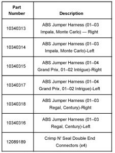
Replace original wheel speed sensor harnesses by splicing in revised wheel speed sensor harnesses. The new design harnesses are of a different length and have revised retention clip locations. Use the following procedure to replace the harnesses.
1. Raise and suitably support the vehicle on a hoist.
2. Disconnect the left wheel speed sensor harness from the sensor/bearing assembly.
3. Remove the harness retainers from the lower control arm.
4. Follow the harness back to the point where the harness enters the larger engine harness conduit.
5. Cut the electrical tape and open the conduit. Select a location where the splice will be within the engine harness conduit. Cut the original harness off.
6. Using GM/Packard Seal and Crimp Connectors, splice the two wires from the new harness to the old. Specific instructions for use of the Seal and Crimp Connectors are printed on the inside of the cardboard overleaf sealing the bag in which the harness is shipped. If Seal and Crimp Connectors are not available, you may use the crimp and solder type included with the harness kit.
7. Retape the conduit closed making sure to create an effective seal against road splash.
8. Route the replacement harness following the same path as the original. Fully seat the 4 retainers into the control arm.
Note: In the next step you will be required to measure the distance between the last retaining clip in the control arm and the end of the electrical plug that connects to the wheel speed sensor. Failure to properly perform this measurement and suitably adjust the harness may result in entanglement or infringement on the tie rod stud.
9. Hold the end of the new electrical harness and stretch it firmly. Due to manufacturing tolerances, you will need to measure from the end of the plug (that attaches to the wheel speed sensor) to the rear edge of the first retaining clip. This distance must not exceed 24.7 cm (9.75 in). If the distance is equal to or greater than 24.7 cm (9.75 in), you must move the retaining clip to allow more slack at the control arm and less between the wheel speed sensor and the retainer. Repeat the measurement until properly adjusted.
10. Disconnect the right wheel speed sensor harness from the sensor/bearing assembly.
11. Remove the harness retainers from the lower control arm.
12. Follow the harness back to the point where the harness enters the larger conduit.
13. Cut the electrical tape and open the conduit. Select a location where the splice will be within the larger harness conduit. Cut the original harness off.
14. Using GM/Packard Seal and Crimp Connectors, splice the two wires from the new harness to the old. Specific instructions for use of the Seal and Crimp Connectors are printed on the inside of the cardboard overleaf sealing the bag in which the harness is shipped. If Seal and Crimp Connectors are not available, you may use the crimp and solder type included with the harness kit.
15. Retape the conduit closed making sure to create an effective seal against road splash.
16. Route the replacement harness following the same path as the original. Fully seat the 4 retainers into the control arm.
Note: In the next step you will be required to measure the distance between the last retaining clip in the control arm and the end of the electrical plug that connects to the wheel speed sensor. Failure to properly perform this measurement and suitably adjust the harness may result in entanglement or infringement on the tie rod stud.
17. Hold the end of the new electrical harness and stretch it firmly. Due to manufacturing tolerances, you will need to measure from the end of the plug (that attaches to the wheel speed sensor) to the rear edge of the first retaining clip. This distance must not exceed 24.7 cm (9.75 in). If the distance is equal to or greater than 24.7 cm (9.75 in), you must move the retaining clip to allow more slack at the control arm and less between the wheel speed sensor and the retainer. Repeat the measurement until properly adjusted.
Sunday, October 26th, 2008 AT 4:40 PM