1999 Chevy Astro Short List of Sensors for no-start?

Tiny
JERRYK1234
  • MEMBER
  • 1999 CHEVROLET ASTRO
  • 6 CYL
  • 2WD
  • AUTOMATIC
  • 106,000 MILES
Hello,

My '99 Astro has had various intermittant problems over the past few years, culminating with a no-start
condition. The engine burbles and hiccups, but will
not start. This has happened occasionally over the past
few years, mostly on cold days when the car has not
been used for a while.

AT THIS TIME

* The starter motor cranks energetically
* There is good fuel pressure ( 60PSI ) measured at the rail.
* There is good spark
HOWEVER
* I scoped the output to fuel injector 1, and
there are no pulses. Well, there is an occasional
pulse ( accompanied by an engine burble ). It seems
clear to me that the no-start condition is caused by the
ECU not supplying a pulse train to the injectors.

I have verified the following sensors:

* TPS - it was worn, I replaced it.
* MAF - numbers during cranking seem reasonable
thru OBDII
* MAP - tested it with OBDII and a hand vacuum pump
* CKP( crankshaft position) - tested it with a scope and
a digital dwell meter. Chevy spec is 40% to
60% duty cycle, measures 51%. Nice pulses.
* IAT ( intake air ) - reading seemed reasonable - 64F -
via the OBDII
* Coolant temperature sensor - also reasonable via OBDII

I am thinking that the reasonable thing to do now is to replace the ECU, but

My question to you at this time is:

What is the short list of sensors that must work in order to START THE CAR? At this time, I only care about
the no-start. I believe that leaves out the oxygen sensors, because the car has to be able to start before they warm up.

If I replace the ECU, there are rebuilts available for modest cost. As a professional, do you have experience with these? Do they work well, or result in a lot of callbacks?

Thank you,

- Jerry Kaidor
Tuesday, January 19th, 2010 AT 11:26 AM

18 Replies

Tiny
MERLIN2021
  • MECHANIC
  • 17,250 POSTS
Jerry, first this is the IAT and ECT do the show within 5 degrees of each other? And do the OHM show what it should be as well as the temp? Here's the table, and the readings are the same for both sensors. Check ignition switch as switch signal must be present for injectors to fire.


https://www.2carpros.com/forum/automotive_pictures/62217_ECTGM_2.jpg


Is the service engine light on? You did say you have an OBD II scanner? A bad PCM will set a code from 600 to 606, What does the security light on the dash do when you try to start it? Let do a Passlock relearn to rule out the security system ok? Here's how: Have you done a relearn on the pass-key?
GM PASS LOCK RELEARN- Ignition to "run" position, try to start and let key return to "run" position
Approx ten minutes security light will go off
Turn key "off" and wait 5 seconds
Repeat 2 more times for a total of 3 relearns.
Turn key off, then start it
Was this
answer
helpful?
Yes
No
Tuesday, January 19th, 2010 AT 5:19 PM
Tiny
JERRYK1234
  • MEMBER
  • 15 POSTS
The IAT and ECT do show reasonable values via the OBDII. I have not ohmed them out yet ( I assume that's what you mean by OHM? ).

There is no security light. And the system is producing occasional fuel injector pulses, as well as good spark. I believe that spark is also produced by the ECU. By "good spark", I mean constant sparks at a grounded sparkplug stuck into the ignition coil output lead.

The truck has a history of intermittant failures to start, mostly occuring after a period of not being used ( a few to several days ).

I actually have two OBDII scan tools, one from the autoparts store that reads codes and can reset the MIL, the second one PC-based, that can also read PIDs.

DTCs that have been produced by this truck over the past few years include:

P0155 - heated O2 sensor failure
( I replaced the O2 sensor no difference )

P0300 - misfire
( once in a while )

P0101 - MAF failure

This last was recent, and coincided with a loss of power such that I had to have the truck towed home. I cleaned the MAF, and verfied reasonable
readings via the OBDII, as well as the MAP at that time. I do not think the no-start is directly related to this problem, because at that time it would still start and run.

Thank you for the Passlock procedure, although I do not think this is security-related.

Do problems with the ECM ALWAYS result in a reasonable (600-606 ) DTC?

When it stops raining, I'll go out, perform the passlock and ohm those temperature sensors.

- Jerry Kaidor
Was this
answer
helpful?
Yes
No
+1
Tuesday, January 19th, 2010 AT 6:02 PM
Tiny
MERLIN2021
  • MECHANIC
  • 17,250 POSTS
To test the spark out. Leave the plug in it location and test with it's own wire. Test 2 plugs at the same time, here's the book on injector and ignition testing. INJECTOR CIRCUIT DIAGNOSIS 4.3L, 5.0L, 5.7L & 7.4L 1. Perform On-Board Diagnostic (OBD) system check. See ON-BOARD DIAGNOSTIC (OBD) SYSTEM CHECK in appropriate SELF-DIAGNOSTICS article. After performing OBD system check, go to next step. 2. Disconnect injector harness connector at intake manifold. Turn ignition on with engine off. Using a test light connected to ground, probe injector ignition feed circuits. See appropriate wiring diagram in WIRING DIAGRAMS article. If test light illuminates at all injector feed circuits, go to step 6. If test light does not illuminate at all injector feed circuits, go to next step. 3. If test light illuminates for only some of the injector circuits, go to step 5. If test light does not illuminate for any injector circuit, go to next step. 4. Check ECM I fuse (15-amp on 4.3L; 20-amp on all others), located in underhood fuse block. If fuse is open, go to step 10. If fuse is okay, go to step 11. 5. Locate open in faulty injector feed circuit. After locating faulty circuit, go to step 12. 6. Install injector test light to each injector circuit, one at a time. Crank engine. If injector test light flashes on each injector, check fuel injector(s). See FUEL SYSTEM in appropriate SYSTEM & COMPONENT TESTING article. If injector test light does not flash for each injector circuit, go to next step. 7. If injector test light was on steady on any injector circuit, go to next step. If injector test light did not illuminate on any injector circuit, go to step 9. 8. Install injector test light to faulty injector circuit. Turn ignition off. Disconnect Red VCM harness connector. Turn ignition on with engine off. If injector test light is off, go to step 16. If injector test light remains illuminated, go to step 13. 9. Check for an open in injector control circuit. If circuit is open, go to step 12. If circuit is okay, go to step 14. 10. Locate short to ground in injector control circuit. After locating short, go to step 12. 11. Repair open or short to ground for all injector feed circuits. After repairs, go to step 17. 12. Repair circuit as necessary. After repairs, go to step 17. 13. Repair short to ground in injector control circuit. After repairs, go to step 17. 14. Check terminal contact at VCM harness connector. If terminal contact is faulty, go to next step. If terminal contact is okay, go to step 16. 15. Repair terminal contact as necessary. After repairs, go to step 17. 16. Replace VCM. Perform VCM reprogramming procedures. After repairs, go to next step. 17. Using scan tool, select DTC, CLEAR INFO function. Attempt to start engine. If engine starts and continues to run, go to next step. If engine does not start, or starts and stalls, go to step 2. 18. Allow engine to reach normal operating temperature. Using scan tool, select DTC, FAILED THIS IGN function. If any other DTCs are present, diagnose DTCs. See appropriate SELF- DIAGNOSTICS article. If no other DTCs are present, go to next step. 19. Using scan tool, select CAPTURE INFO, REVIEW INFO function. If additional undiagnosed DTCs are present, diagnose DTCs. See appropriate SELF-DIAGNOSTICS article. If additional NOTE: This test only applies to vehicles equipped with a VCM. DTCs are not present, system is okay.
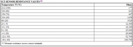
NO START-ENGINE CRANKS OKAY (4.3L, 5.0L, 5.7L & 7.4L) General Inspection 1. Ensure proper starting procedure is being used. Visually check vacuum hoses for splits, kinks and proper connections, as shown on Vehicle Emission Control Information label. Check ignition wires for cracking, hardness and proper connections at both coil pack and spark plugs. 2. Remove spark plugs. Check and replace as necessary. In very cold temperatures, ensure oil is proper viscosity and not contaminated with gasoline. Ignition System 1. Perform On-Board Diagnostic (OBD) system check. See ON-BOARD DIAGNOSTIC (OBD) SYSTEM CHECK in appropriate SELF-DIAGNOSTICS article. After performing OBD system check, go to next step. 2. Attempt to start engine. If engine starts and continues to run, see appropriate TROUBLE SHOOTING - NO CODES article. If engine does not start, go to next step. 3. For "P" series, go to next step. On all models except "P" series, install scan tool. Monitor VTD FUEL DISABLED parameter while cranking engine. If VTD FUEL DISABLED parameter is active while cranking engine, diagnose anti-theft system. See appropriate ANTI-THEFT SYSTEMS article in ACCESSORIES & EQUIPMENT. If VTD FUEL DISABLED parameter is not active while cranking engine, go to next step. 4. Using scan tool, monitor Throttle Position (TP) sensor voltage with throttle closed. If TP sensor voltage is greater than 2.5 volts, go to DTC P0121. See appropriate SELF- DIAGNOSTICS article. If TP sensor voltage is 2.5 volts or less, go to next step. 5. Using scan tool, monitor Engine Coolant Temperature (ECT) sensor. If ECT sensor value is less than -22 °F (-30 °C), go to DTC P0118. See appropriate SELF-DIAGNOSTICS article. If ECT sensor value is -22 °F (-30 °C) or greater, go to next step. 6. Using Spark Tester (J-26792), check for spark at 2 spark plug wires while cranking engine. If spark is present at both wires, go to next step. If spark is not present at both wires, diagnose components and power, ground and signal circuits related to ignition system. See appropriate wiring diagram in WIRING DIAGRAMS article. Also see BASIC IGNITION SYSTEM CHECKS. Repair as necessary. 7. Turn ignition off. Reconnect spark plug wires. Connect fuel pressure gauge. Turn ignition on with engine off. Observe fuel pressure. If fuel pressure is 55-60 psi (3.9-4.3 kg/cm 2 ), go to next step. If fuel pressure is not as specified, diagnose fuel system. See BASIC FUEL SYSTEM CHECKS (GASOLINE ENGINES). 8. Turn ignition off. Disconnect fuel injector harness connector at intake manifold. Using a test NOTE: Before performing the following tests, check battery condition, engine cranking speed and for adequate fuel in tank. NOTE: VCM data is deleted when using scan tool CLEAR INFO function. Before clearing DTCs, use scan tool CAPTURE INFO function to record FREEZE FRAME and FAILURE RECORDS data. Light connected to ground, probe each fuel injector feed circuit while cranking engine. See appropriate wiring diagram in WIRING DIAGRAMS article. If test light illuminates for each circuit, perform fuel injector coil test. See FUEL SYSTEM (GASOLINE) in appropriate SYSTEM & COMPONENT TESTING article. Also, check for any engine mechanical problems. Repair as necessary. If test light does not illuminate, diagnose fuel injector circuit. See FUEL SYSTEM (GASOLINE) in appropriate SYSTEM & COMPONENT TESTING article.
1/19/2010 .
Was this
answer
helpful?
Yes
No
Tuesday, January 19th, 2010 AT 6:19 PM
Tiny
MERLIN2021
  • MECHANIC
  • 17,250 POSTS
If 0101 is showing up, Will it start with the MAF unplugged?
Was this
answer
helpful?
Yes
No
Wednesday, January 20th, 2010 AT 8:10 AM
Tiny
MERLIN2021
  • MECHANIC
  • 17,250 POSTS
File has been sent again.
Was this
answer
helpful?
Yes
No
Wednesday, January 20th, 2010 AT 11:54 AM
Tiny
MERLIN2021
  • MECHANIC
  • 17,250 POSTS
Inbox : Message
From: jerryk1234
To: merlin2021
Posted: Wed Jan 20, 2010 4:45 pm
Subject: Re: Check email
So,

Would this be an accurate short list? In other words
if all these things are present, the ECU WILL deliver fuel injection pulses to start the car:

* Power to the ECU, both the "run" and "run+start" lines.

* All ECU grounds grounded.

Following signals present and proper:
* CKP
* CMP
* MAF
* MAP
* TPS
* IAT
* ECT

O2 sensors OK, at least to the extent that they do not
short out the bias signal coming out of the ECU.
Yes. Fuel Pump An in-tank, electric fuel pump delivers fuel to injector(s) through an in-line fuel filter. The pump is designed to supply fuel pressure in excess of vehicle requirements. The pressure relief valve controls maximum fuel pump pressure. On Central Sequential Port Injection (CSI) systems, pressure regulator is mounted to fuel metering body under upper intake manifold. On Sequential Multiport Fuel Injection (SFI), pressure regulator is attached to end of fuel rail. Pressure regulator keeps fuel available to injector(s) at a constant pressure. Excess fuel is returned to fuel tank through pressure regulator return line. When ignition switch is turned to ON position, PCM turns on electric fuel pump by energizing fuel pump relay. PCM keeps pump on if engine is running or cranking (PCM is receiving reference pulses from ignition module). If there are no reference pulses, PCM turns pump off within 2 seconds after ignition is turned on. Most models also include a second control path through the oil pressure switch which will turn the fuel pump on after the switch detects oil pressure. Cranking time will be longer if fuel pump does not receive current until oil pressure switch contacts close. Fuel Pressure Regulator (CSI) Fuel pressure regulator is a diaphragm-operated relief valve with injector pressure on one side and manifold pressure (vacuum) on the other. Pressure regulator maintains a pressure of 60-66 psi (4.2- 4.6 kg/cm 2 ) under all operating conditions. Pressure regulator is a factory preset, nonadjustable, spring-loaded diaphragm attached to CSI assembly. Spring tension maintains a constant fuel pressure to injector regardless of engine load. Fuel Pressure Regulator (SFI) Fuel pressure regulator is a diaphragm-operated relief valve with injector pressure on one side and manifold pressure (vacuum) on the other. Pressure regulator maintains a pressure of 56-62 psi (3.9- 4.4 kg/cm 2 ) under all operating conditions. Pressure regulator compensates for engine load by increasing fuel pressure when low manifold vacuum is experienced. Fuel Pump Relay When ignition switch is turned to ON position, PCM turns electric fuel pump on by energizing fuel pump relay. PCM keeps relay energized if engine is running or cranking (PCM is receiving reference pulses from ignition module). If there are no reference pulses, PCM turns pump off within 2-20 seconds after key on. As a back-up system to fuel pump relay, the oil pressure switch also activates fuel pump. The oil pressure switch is normally open until oil pressure reaches about 4 psi (.28 kg/cm 2 ). If fuel pump relay fails, the oil pressure switch closes when oil pressure is obtained and operates the fuel pump. Cranking time will be longer if fuel pump does not receive current until oil pressure switch contacts close. Oil pressure switch may be combined into a single unit with an oil pressure gauge sending unit or sensor. PCM monitors fuel pump circuit between fuel pump relay/oil pressure switch and fuel pump, enabling PCM to determine if fuel pump is being energized by fuel pump relay or oil pressure switch. A failure in this monitored circuit results in the setting of a related diagnostic trouble code in PCM memory. For additional information on fuel pump activation, see appropriate BASIC DIAGNOSTIC PROCEDURES and SYSTEM & COMPONENT TESTING articles. FUEL CONTROL The PCM, using input signals, determines adjustments to the air/fuel mixture to provide the optimum ratio for proper combustion under all operating conditions. Fuel control systems can operate in the "open loop" or "closed loop" mode. Open Loop When engine is cold and engine speed is greater than 400 RPM, PCM operates in "open loop" mode. In "open loop" mode, PCM calculates air/fuel ratio based upon coolant temperature and MAP or MAF sensor readings. Engine remains in "open loop" mode until O2S reaches operating temperature, coolant temperature reaches a preset temperature and a specific period of time has elapsed after engine starts. Closed Loop When O2S reaches operating temperature, coolant temperature reaches a preset temperature and a specific period of time has passed since engine start-up, PCM operates in "closed loop" mode. In "closed loop" mode, PCM controls air/fuel ratio based upon O2S signals (in addition to other input parameters) to maintain as close to a 14.7:1 air/fuel ratio as possible. If O2S cools off (due to excessive idling) or a fault occurs in O2S circuit, vehicle will re-enter "open loop" mode. On most engines, O2S is equipped with an internal heating element. This type of sensor is known as a Heated Oxygen Sensor (HO2S). The heating element enables system to reach and maintain "closed loop" mode sooner, even during periods of extended idle.
1/20/2010 .
Was this
answer
helpful?
Yes
No
Wednesday, January 20th, 2010 AT 5:15 PM
Tiny
JERRYK1234
  • MEMBER
  • 15 POSTS
OK,

I got pretty well convinced that the problem was the ECU, so I replaced it. That was quite an adventure. All the autoparts store sell the things, but nobody here on the SF peninsula will flash them except for the dealers.
And the dealers want you to have the car towed to them.
I found a professional-level programming device on the web, called them and asked - "You got any customers in the SF Bay area?" They pointed me to a parts store in San Jose that would do it.

Installed the new ECU, performed the Passlock procedure. STILL NO START. :(

Still, things are different. Now there are regular F.I. Pulses while cranking. They occur at about 1 second intervals, and are 60mS long. So it's my judgement that the ECU really did need to be replaced.

Now I need to go back to the basics. Here's the current OBDII data while cranking:

MAF =.7 pounds per minute
TPS = 0%
O2 sensors - all wobbling around just a hair under.5V. The lowest is bank2 sensor 3, at 0.48V
IAT = 48.2F
MAP = 13.8PSI
Engine Load = 3%
RPM = 170
ECT = 48.2F

. The MAF sensor scopes out to pulses at 400 microsecond intervals, AKA 2500Hz.

I wondered if the "fuel" in the fuel rail ( where I'm seeing 60PSI static, 55PSI while cranking ) is really fuel. So I pushed the button on the pressure gauge
and squirted out some fuel into a small bucket - sure looks like gas to me. Sort of yellow, volatile, smells like gas, no globules of water, feels a little lighter than water when you slosh it.

So I guess I need to go back to the basics - fuel, spark, compression. Will pull sparkplugs tomorrow IF it stops raining!

- Jerry Kaidor
Was this
answer
helpful?
Yes
No
Friday, January 22nd, 2010 AT 6:01 PM
Tiny
MERLIN2021
  • MECHANIC
  • 17,250 POSTS
Check the cam sensor, it supplies the timing of the injectors.
Was this
answer
helpful?
Yes
No
Friday, January 22nd, 2010 AT 9:20 PM
Tiny
JERRYK1234
  • MEMBER
  • 15 POSTS
The problem is fixed. It was indeed the cam sensor.
The sensor was not faulty! It was just dirty, with a very specific type of dirt.

The tip of the central distributor shaft had rusted. Rotation of the shaft had gradually dispersed rust throughout the distributor.

I theorize that in the damp, the rust became just a bit conductive, and therefore magnetic - just enough to confuse the sensor at slow speeds. The starter motor cranks the engine at about 150 RPM, the cam goes half that fast - so only about 1 revolution a second.

To fix it, I laid a SERIOUS clean on that distributor. I used Q-tips and lacquer thinner, compressed air. I also stripped the rust from the end of the center shaft with a dremel, and painted it with Rustoleum primer and top coat. I cleaned the distributor cap and rotor in an ultrasonic bath.

Put it all together, it started instantly.

It just rained all night. If it starts this morning, it's a good fix ( I've been fooled before ).

- Jerry Kaidor
Was this
answer
helpful?
Yes
No
+1
Friday, February 5th, 2010 AT 11:27 AM
Tiny
MERLIN2021
  • MECHANIC
  • 17,250 POSTS
How much did you spend on this? Electronics. Wonderful arent they!
Was this
answer
helpful?
Yes
No
+1
Friday, February 5th, 2010 AT 12:44 PM
Tiny
JERRYK1234
  • MEMBER
  • 15 POSTS
*** Yup.

Lessee: $300 for a replacement computer
$ 65 for a good OBDII interface
$ 20 for software

Plus there were a few other problems besides the no-start:
$500 for a catalytic converter ( CA-legal )
$140 for a radiator
$20 for an O2 sensor ( to fill the extra hole in the cat )
$12 for cat gaskets

. So about a grand total. But now I have a totally functional van with 106K on it. I can reasonably expect to drive it another 40K miles with nothing but routine maintenance.

And I actually _do_ love electronics. Got my ham license when I was 13. Worked in the industry for many years, first as a tech, then as a computer programmer, specializing in embedded systems.

Now I feel much more confidence that I can handle future electronic snafus without undue heartburn.
Thanks for your help!

- Jerry
Was this
answer
helpful?
Yes
No
+1
Friday, February 5th, 2010 AT 1:45 PM
Tiny
MERLIN2021
  • MECHANIC
  • 17,250 POSTS
OK. Your welcome
Was this
answer
helpful?
Yes
No
+1
Friday, February 5th, 2010 AT 3:36 PM
Tiny
JERRYK1234
  • MEMBER
  • 15 POSTS
*** Well, it's tomorrow. Truck still starts instantly. Fix is good!

- Jerry
Was this
answer
helpful?
Yes
No
+1
Friday, February 5th, 2010 AT 5:17 PM
Tiny
MERLIN2021
  • MECHANIC
  • 17,250 POSTS
Jerry, next time you nedd help, wait for my answer, or which ever Moderator gets you, It's great that it's running, but I do testing with donors, then parts replacement, OK? I never mentioned replacing the ECM! Or anything for that matter. The Cam sensor was kinda a no brainer for spark. Lets save some dough next time!
Was this
answer
helpful?
Yes
No
+1
Friday, February 5th, 2010 AT 6:46 PM
Tiny
JERRYK1234
  • MEMBER
  • 15 POSTS
But it DID have SPARK! There was never any shortage of spark. There was spark, all the other inputs were OK as far as I could tell. Believe, me I agonized over changing the ECM for a couple of days! I do NOT like shotgunning.

Again, there was SPARK, but no FI pulses. The CMP waveform looked OK on my oscilloscope. Which, admittedly was a little battery-powered job. I just didn't feel like dragging out my big 4-trace Tektronix.
Also, remember that the starter motor was running all this time. I did not have TIME to fiddle and diddle with viewing the waveform just so - or I would have burned out the starter. And I reasoned - how could there a bad CMP with GOOD SPARK?

As a private owner, I do not have the luxury of swapping "donors" - I had exactly one ECM - the one that was in the car. I generated my "short list" of
things that had to work to start, and went down it, verifying each signal, power, ground either with the oscilloscope, DMM, or OBDII. When I was done,
I figured the ECM was, if not a sure thing, then at least a good bet.

If I had replaced the CMP when I had GOOD SPARK, I would still be guilty of shotgunning - but at least with something cheaper. But with GOOD SPARK, I couldn't see the percentage.

I was not happy to be changing out the ECM, not so much because it was expensive, but more because it felt too much like shotgunning. I have spent a great deal of my professional life finding and fixing problems of one kind or another. But one important thing I gained by replacing the ECM - reasonable confidence that it was now OK, and I needed to look for my problem elsewhere. Interestingly, the new ECM did not behave exactly the same as the old one - it DID deliver FI pulses. But the spark was grossly off time.
To the point where sparks were being delivered to the WRONG CYLINDERS. I troubleshot this by connecting the spark coil directly to cylinder #1 with a patch cord.
At this point, zeroing in on the CMP was a no-brainer.

Again, with the old ECM, there was GOOD SPARK and no FI pulses. With the new ECM, there were FI pulses and grossly mistimed spark.

When I was a line technician for Northern Telecom, we had one "tech" ( I use the term advisedly ) who discovered a new way to troubleshoot circuit boards: He would first tag the entire leftmost row for the rework girls to replace. If that didn't fix it, he'd tag the next row, then the next. Ick.

- Jerry Kaidor
Was this
answer
helpful?
Yes
No
Saturday, February 6th, 2010 AT 1:22 PM
Tiny
MERLIN2021
  • MECHANIC
  • 17,250 POSTS
Spark is generated by the CKP, not the CMP! Cmp generates injector timing.
Was this
answer
helpful?
Yes
No
Sunday, February 7th, 2010 AT 10:56 AM
Tiny
JERRYK1234
  • MEMBER
  • 15 POSTS
Actually, spark is generated by both CMP and CKP.

* With CKP only, how could it tell the difference between the compression stroke and the exhaust stroke? It's the same crankshaft position. They MIGHT be able to do the "distributorless ignition" trick of sending sparks on both the compression and exhaust strokes - I'm not quite visualizing the time sequence,

****HOWEVER****

* After replacing the ECM, I had good fuel injector pulses - at least regular pulses of appropriate length, don't know if they were "timed" correctly - but grossly mistimed spark. I think the spark was 360 degrees off, because there was nary a burble.
Cleaning the distributor got the spark back where it belonged. Vrrom! That proves that ( at least in this design ) spark uses the CMP as well as the CKP.

- Jerry
Was this
answer
helpful?
Yes
No
Sunday, February 7th, 2010 AT 11:13 AM
Tiny
MERLIN2021
  • MECHANIC
  • 17,250 POSTS
Thats true Jerry, but it originates at the CKP, into the ecm out to cmp. Cmp in to ecm for injector timing. Ecm out to injectors! Unplug CKP, you get no spark!
Was this
answer
helpful?
Yes
No
Sunday, February 7th, 2010 AT 11:34 AM

Please login or register to post a reply.

Sponsored links