Good evening,
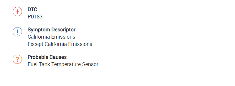
The code is for the fuel tank temperature sensor. It is part of the fuel pump itself in the fuel tank.
I attached the flow chart for checking it and some pictures.
https://www.2carpros.com/articles/how-to-check-wiring
Roy
The fuel tank temperature sensor is used to detect the fuel temperature inside the fuel tank. The sensor modifies a voltage signal from the ECM. The modified signal returns to the ECM as the fuel temperature input. The sensor uses a thermistor which is sensitive to the change in temperature. The electrical resistance of the thermistor decreases as temperature increases.
imageOpen In New TabZoom/Print
DTC Logic
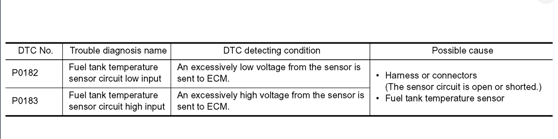
DTC DETECTION LOGIC
image
DTC CONFIRMATION PROCEDURE
1. PRECONDITIONING
If DTC Confirmation Procedure has been previously conducted, always turn ignition switch OFF and wait at least 10 seconds before conducting the next test.
GO TO 2.
2. PERFORM DTC CONFIRMATION PROCEDURE
1.Turn ignition switch ON and wait at least 5 seconds.
2.Check 1st trip DTC.
Is 1st trip DTC detected?
YES- Go to "Diagnosis Procedure".
NO- INSPECTION END
Diagnosis Procedure
1. CHECK GROUND CONNECTION
1.Turn ignition switch OFF.
2.Check ground connection E9. Refer to Ground Inspection in See: Vehicle > Initial Inspection and Diagnostic Overview > Circuit Inspection.
Is the inspection result normal?
YES- GO TO 2.
NO- Repair or replace ground connection.
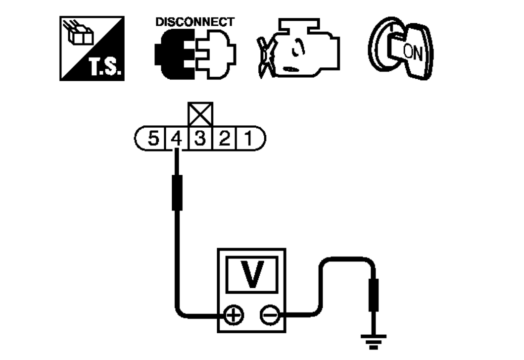
2. CHECK FUEL TANK TEMPERATURE SENSOR POWER SUPPLY CIRCUIT
1.Turn ignition switch OFF.
2.Disconnect "fuel level sensor unit and fuel pump" harness connector.
3.Turn ignition switch ON.
imageOpen In New TabZoom/Print
4.Check the voltage between "fuel level sensor unit and fuel pump" harness connector and ground.
imageOpen In New TabZoom/Print
Is the inspection result normal?
YES- GO TO 4.
NO- GO TO 3.
3. DETECT MALFUNCTIONING PART
Check the following.
Harness connectors E29, B10
Harness for open or short between ECM and "fuel level sensor unit and fuel pump"
Repair open circuit or short to ground or short to power in harness or connector.
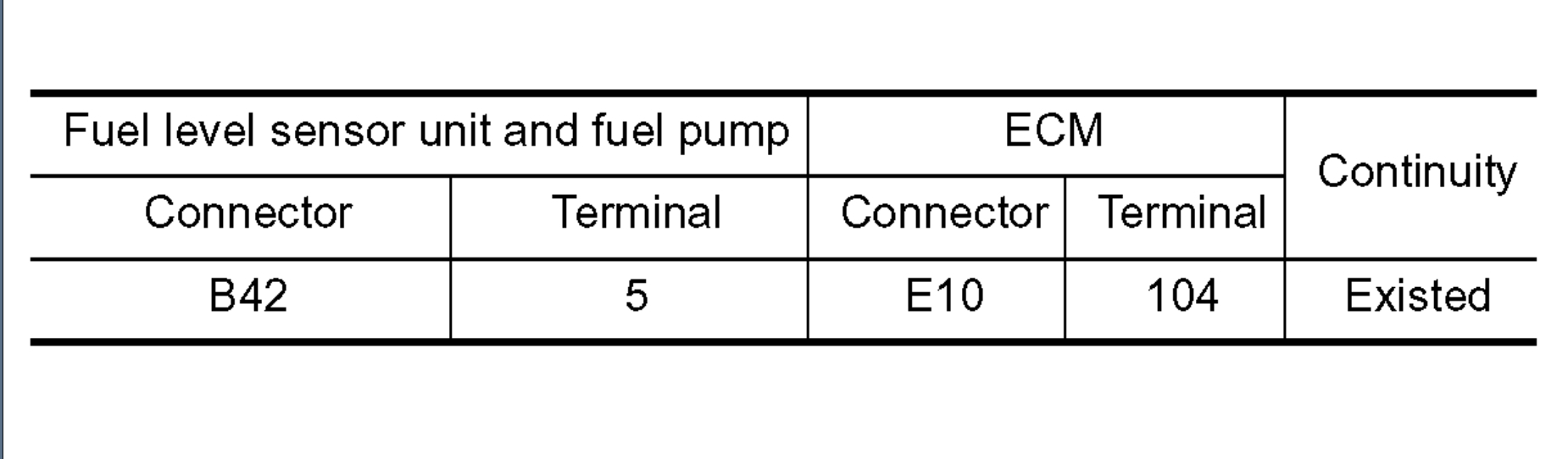
4. CHECK FUEL TANK TEMPERATURE SENSOR GROUND CIRCUIT FOR OPEN AND SHORT
1.Turn ignition switch OFF.
2.Check the continuity between "fuel level sensor unit and fuel pump" harness connector and ECM harness connector.
imageOpen In New TabZoom/Print
3.Also check harness for short to ground and short to power.
Is the inspection result normal?
YES- GO TO 6.
NO- GO TO 5.
5. DETECT MALFUNCTIONING PART
Check the following.
Harness connectors B1, M6
Harness connectors E30, M1
Harness for open or short between "fuel level sensor unit and fuel pump" and ECM
Repair open circuit or short to ground or short to power in harness or connector.
6. CHECK FUEL TANK TEMPERATURE SENSOR
Refer to "Component Inspection".
Is the inspection result normal?
YES- GO TO 7.
NO- Replace "fuel level sensor unit and fuel pump". See: Fuel Pump > Removal and Replacement > Removal and Installation.
7. CHECK INTERMITTENT INCIDENT
See: Vehicle > Initial Inspection and Diagnostic Overview > Intermittent Incident.
INSPECTION END
Component Inspection
1. CHECK FUEL TANK TEMPERATURE SENSOR
1.Turn ignition switch OFF.
2.Disconnect "fuel level sensor unit and fuel pump" harness connector.
3.Remove fuel level sensor unit. See: Fuel Pump > Removal and Replacement > Removal and Installation.
imageOpen In New TabZoom/Print
4.Check resistance between "fuel level sensor unit and fuel pump" terminals by heating with hot water as shown in the figure.
imageOpen In New TabZoom/Print
Is the inspection result normal?
YES- INSPECTION END
NO- Replace "fuel level sensor unit and fuel pump". Refer to
See: Fuel Pump > Removal and Replacement > Removal and Installation.
FUEL LEVEL SENSOR UNIT, FUEL FILTER AND FUEL PUMP ASSEMBLY
Removal and Installation
REMOVAL
WARNING:
Read "General Precautions" before working on the fuel system.
See: Vehicle > Technician Safety Information > General Precautions.
1.Unscrew the fuel filler cap to release the pressure inside the fuel tank.
2.Release the fuel pressure from the fuel lines. See: Fuel Pressure > Component Tests and General Diagnostics > Fuel Pressure (QR25DE For California), See: Fuel Pressure > Component Tests and General Diagnostics > Fuel Pressure (QR25DE Except For California), See: Fuel Pressure > Component Tests and General Diagnostics > Fuel Pressure (QR25DE for Mexico), See: Fuel Pressure > Component Tests and General Diagnostics > Fuel Pressure (VQ35DE).
3.Disconnect the battery negative terminal.
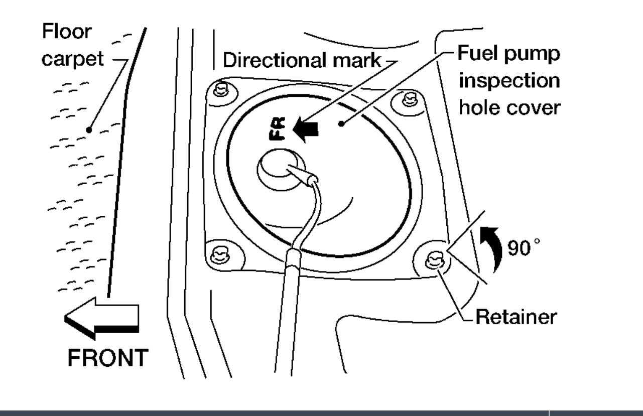
4.Remove the rear seat cushion. See: Seats > Removal and Replacement > Sedan for Sedan or See: Seats > Removal and Replacement > Coupe for Coupe.
imageOpen In New TabZoom/Print
5.Turn the four retainers 90 in a clockwise direction and remove the fuel pump inspection hole cover.
FL
imageOpen In New TabZoom/Print
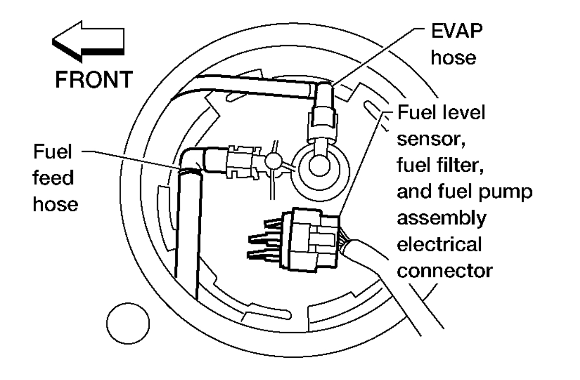
6.Disconnect the fuel level sensor, fuel filter, and fuel pump assembly electrical connector, EVAP hose quick connector, and the fuel feed hose quick connector from the fuel level sensor unit, fuel filter, and fuel pump assembly.
imageOpen In New TabZoom/Print
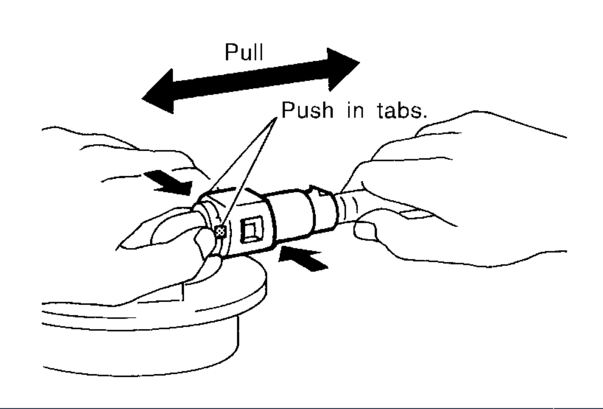
Remove the quick connector as follows:
Hold the sides of the connector, push in tabs and pull out the tube.
If the connector and the tube are stuck together, push and pull several times until they start to move. Then disconnect them by pulling.
CAUTION:
The tube can be removed when the tabs are completely depressed. Do not twist it more than necessary.
Do not use any tools to remove the quick connector.
Keep the resin tube away from heat. Be especially careful when welding near the tube.
Prevent acid liquid such as battery electrolyte, etc. from getting on the resin tube.
Do not bend or twist the tube during installation and removal.
Only when the tube is replaced, remove the remaining retainer on the tube or fuel level sensor, fuel filter, and fuel pump assembly.
When the tube or fuel level sensor, fuel filter, and fuel pump assembly is replaced, also replace the retainer with a new one (green colored retainer).
imageOpen In New TabZoom/Print
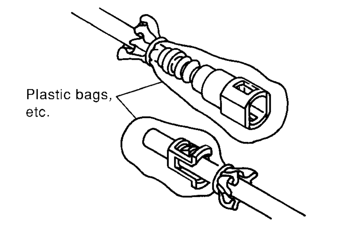
To keep the connecting portion clean and to avoid damage and foreign materials, cover them completely with plastic bags or something similar.
imageOpen In New TabZoom/Print
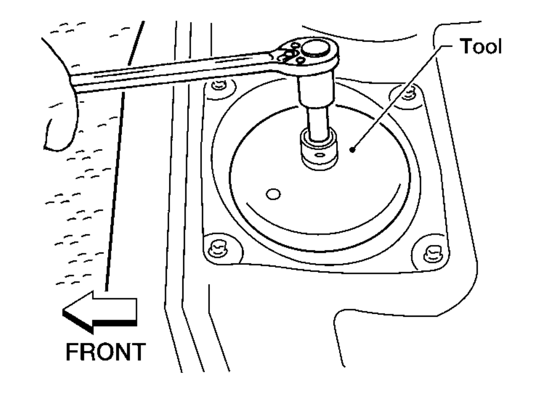
7.Remove the lock ring using a socket drive handle and Tool as shown.
Tool number: KV991J0090 (J-46214)
CAUTION:
Discard the lock ring if damaged or distorted.
imageOpen In New TabZoom/Print
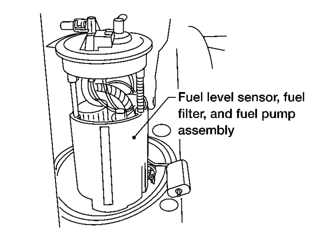
8.Remove the fuel level sensor, fuel filter, and fuel pump assembly. Remove and discard the O-ring.
CAUTION:
Do not bend the float arm during removal.
Discard the O-ring. Do not reuse O-ring.
INSPECTION AFTER REMOVAL
Inspect the fuel level sensor, fuel filter, and fuel pump assembly for any defects and foreign materials. Replace as necessary.
Images (Click to enlarge)
Dec 2, 2020 at 3:48 PM