Car turn signal bulb has only 9 volts

Tiny
L TIATOM
  • MEMBER
  • 2011 HYUNDAI I20
  • 1.2L
  • 4 CYL
  • 4WD
  • 35,000 MILES
My car's turn signal bulb has only 9 V drops across the bulb. All lighting systems are okay. I just wanted to know the voltage drop across it.

Is not it supposed to be 12 V? If not, why only 9 V across the bulb?

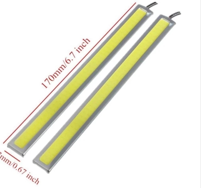
I connect one end of 12 v led cob light and other end to ground. Activated the turn signal circuit, surprisingly, the led does not come on at all, which is taking me to verify out that the voltage drops is only 9 V! Why?

The led cob light when connected to the battery directly is lighting up as it should be.
Thursday, March 5th, 2020 AT 10:18 PM

19 Replies

Tiny
SCGRANTURISMO
  • MECHANIC
  • 4,897 POSTS
Hello,

This is because you have unwanted resistance in the turn signal circuit somewhere. The best way to test the circuit and find out where the unwanted resistance is is by the voltage drop method. Unfortunately we do not have your vehicle in our reference material, so I can not get you an exterior lighting wiring diagram of your vehicle, but I can give you a guide explaining how to test the circuit with the voltage drop method. I have included this in the diagrams down below. Please go through this guide and get back to us with what you are able to find out.

Thanks,
Alex
2CarPros
Was this
answer
helpful?
Yes
No
+1
Thursday, March 5th, 2020 AT 11:39 PM
Tiny
L TIATOM
  • MEMBER
  • 61 POSTS
With key removed from ignition slot.

Some values of resistances of each wires of the coupler individually.

With one end of multi-meter connected to each wire individually and other end of multi-meter to ground. Here are the results:

Pin 1, 3, 5, 6 has same resistance of about 76 ohms.
Pin 4 has 583 ohms.

Pin 2, 7 and 8 show continuity with the buzzer sound coming on.

And, pin 2 is the turn signal wire.
Pin 8 is the ground wire.

Any more ideas where the 3 v is missing?
Was this
answer
helpful?
Yes
No
Friday, March 6th, 2020 AT 4:18 AM
Tiny
SCGRANTURISMO
  • MECHANIC
  • 4,897 POSTS
Hello again,

Testing for resistance using the Ohm's setting on your DMM is not the best way to find out where the problem is, voltage drop is the way to go here. With voltage drop you will be able to pinpoint the exact spot in the circuit that is consuming the 3V that isn't making it to the bulb. Please check out the guide that I sent previously. Basically what you are doing is powering the circuit, turning the turn signal on and then with the DMM in VDC setting, 20V range, put the positive lead on the front part of the piece of the circuit that you want to test and the negative lead on the back part of the piece of the circuit that you are testing and read the voltage that is being dropped across that piece of the circuit. Lets say you want to test the voltage drop across an electrical connector. Put one lead on either side of the connector. If the connector had a bunch of corrosion on the pins and wasn't making a good connection, the voltage drop might be around 2.5V. That means that the electrical current is having to use 2.5V to push the current through that corroded connector, leaving 9.5V to drop across the circuits load. Any piece of the circuit that you do a voltage drop test on shouldn't be above 0.1V. If it is then there is a problem in the piece of the circuit that you just tested and needs to be fixed. Pretty cool, huh. Let me sell you on voltage drop one more time. Let's say you have a piece of the circuit that you are testing has all of the strands of the wire frayed apart except for 1 strand that is intact. Now let's say you are using the DMM in Ohms mode to test for continuity. The DMM would register that there is continuity and everything would seem okay. You can't see the frayed strands of the wire because they are under the wires insulation. But, if you do a voltage drop test across the same piece of the circuit, you would probably get a voltage drop of 9V, or more. Obviously a major problem. Please go through the previously sent guide on how to do voltage drop testing and get back to us with what you find out.

Thanks,
Alex
2CarPros
Was this
answer
helpful?
Yes
No
+1
Friday, March 6th, 2020 AT 9:23 AM
Tiny
L TIATOM
  • MEMBER
  • 61 POSTS
But, surprise thing is that as soon as engine is started, the LED lights up as it should be! 100 percent bright!

This case is very surprising!
Was this
answer
helpful?
Yes
No
Sunday, March 8th, 2020 AT 5:27 AM
Tiny
SCGRANTURISMO
  • MECHANIC
  • 4,897 POSTS
Hello,

Okay, so it is lighting up at full brightness because it is not just running off the battery at this point, but the alternator. The way an alternator charges the battery is it has to produce more voltage than the battery has in order to charge it. The alternator not only charges the battery, but provides voltage to the vehicle systems to run them as well. So the voltage regulator will be allowing anywhere from 14 - 16 volts of current through to charge the battery. Now subtract the 3 Volts that are be used up to push the current through the damaged area of the circuit from that and you will wind up with close to or 12.6 Volts which is why the LED lights up brightly when your vehicle is started. I hope that this helps.

Thanks,
Alex
2CarPros
Was this
answer
helpful?
Yes
No
+1
Sunday, March 8th, 2020 AT 3:37 PM
Tiny
L TIATOM
  • MEMBER
  • 61 POSTS
Here's the data after performing the voltage drop on positive and negative side of the bulb under source voltage of 12.6 v:

Positive side circuit reads max. 0.06 voltage drop.
Negative side circuit reads max. 0.02 voltage drop.

Now, all above data are well within acceptable range.

However, when all the 3 lights, side repeater bulb, turn signal bulb and 12 v, 2 watt LED strip are connected in parallel, and as soon as the turn signal circuit is activated, still the LED doesn't glow at all. It's brightness is very very much dimmed again.
Was this
answer
helpful?
Yes
No
Friday, March 13th, 2020 AT 7:19 PM
Tiny
L TIATOM
  • MEMBER
  • 61 POSTS
Please kindly perform the same tests from you end to find out the same results.

1. 12 v, 21 watt, turn signal bulb.
2. 12 v, 5 watt, side repeater bulb.
3. 12 v, 2 watt, led strip light.
Was this
answer
helpful?
Yes
No
Friday, March 13th, 2020 AT 7:24 PM
Tiny
JACOBANDNICKOLAS
  • MECHANIC
  • 108,230 POSTS
Hi,

I am coming in after a lot has been done. You mention LED's. Are they OEM? If you are running power through the LED to incandescent lights, it will drop voltage.

Also, have you checked the sockets themselves?

Sorry if you have already done these things, just trying to figure out what is happening.

Joe
Was this
answer
helpful?
Yes
No
Monday, March 16th, 2020 AT 7:40 PM
Tiny
L TIATOM
  • MEMBER
  • 61 POSTS
It's aftermarket led strip, 12 v, 2 watt.
Was this
answer
helpful?
Yes
No
Monday, March 16th, 2020 AT 8:08 PM
Tiny
JACOBANDNICKOLAS
  • MECHANIC
  • 108,230 POSTS
What happens if you disconnect the LED's? Does power change to the primary lights? Also, you mentioned they are run in parallel. Are they first or second in the series?

I have to be honest. I have never seen a traditional incandescent lamp work with an LED because they have different power requirements.

One last thought. The flasher unit on this vehicle is designed to work with incandescent bulb. You are changing everything because the LED has less resistance than the incandescent.

Joe
Was this
answer
helpful?
Yes
No
Monday, March 16th, 2020 AT 8:29 PM
Tiny
L TIATOM
  • MEMBER
  • 61 POSTS
The three bulbs, turn signal bulb, side repeater bulb and the led strip are connected in parallel at the same time whose specs are 12v, 21w, 12v, 5w, and 12v, 2 w respectively.
Was this
answer
helpful?
Yes
No
Monday, March 16th, 2020 AT 8:56 PM
Tiny
JACOBANDNICKOLAS
  • MECHANIC
  • 108,230 POSTS
Have you tried a different flasher?
Was this
answer
helpful?
Yes
No
-1
Monday, March 16th, 2020 AT 9:05 PM
Tiny
L TIATOM
  • MEMBER
  • 61 POSTS
No. I have not tried.

However, the same 3 bulbs were tested from independent power source 12 v dc from 220v AC adapter home socket outlet. Still, the led dimmed!

Would be best known the reason if you could try from your end the same 3 bulbs connected in parallel!
Was this
answer
helpful?
Yes
No
Monday, March 16th, 2020 AT 9:11 PM
Tiny
JACOBANDNICKOLAS
  • MECHANIC
  • 108,230 POSTS
I can't answer that one. I have to be honest. When you change power requirements on the same circuit, it never seems to work, especially when you run them parallel. You have checked all resistance and there are no problems. So, either the flasher isn't able to keep up or the two can't work together. And honestly, I feel the two different designs are the cause of the problem.

Joe
Was this
answer
helpful?
Yes
No
Monday, March 16th, 2020 AT 9:14 PM
Tiny
L TIATOM
  • MEMBER
  • 61 POSTS
Even if I used the car battery as power source, and apply the same parallel circuit, still the led strip is dimming!
Was this
answer
helpful?
Yes
No
Monday, March 16th, 2020 AT 9:21 PM
Tiny
JACOBANDNICKOLAS
  • MECHANIC
  • 108,230 POSTS
The power being used by the incandescent lamps is causing it. Interestingly, when LED are installed in place of standard lighting, a resister needs installed to make things work correctly. The resistance in them is minimal. If they are used as a turn signal, the flasher will flash double time thinking there is an open in the circuit. By combining the two, I honestly feel that is the cause of the dimming.

If you place 12v on each light, one at a time, the work correctly. If there is no resistance issues, it is being caused by the differences.
Was this
answer
helpful?
Yes
No
+1
Monday, March 16th, 2020 AT 9:39 PM
Tiny
L TIATOM
  • MEMBER
  • 61 POSTS
But then, how the simple eagle eye white drl lights up as can be seen in YouTube. The light was directly connected to the turn signal circuit, and still all the 3 bulbs glows the same.
Was this
answer
helpful?
Yes
No
Monday, March 16th, 2020 AT 9:45 PM
Tiny
JACOBANDNICKOLAS
  • MECHANIC
  • 108,230 POSTS
Hi,

I wish I had a concrete answer, but I don't. The idea that there are no resistance issues and everything works correctly without the LED's only leaves one possible issue, the LED's.

I will ask others to jump in with this conversation to see what they say.

Joe
Was this
answer
helpful?
Yes
No
+1
Tuesday, March 17th, 2020 AT 4:50 PM
Tiny
94 TRANSAM
  • MECHANIC
  • 680 POSTS
If these 3 lights are wired in series then you may have an issue with the LED being last in the run. Each bulb has its own internal resistance. An 1157 or 3057 for instance has a resistance of 1 ohm which will cause a voltage drop across the bulb, the more bulbs the more voltage drop.

Also the more bulbs the more load is on the circuit. Car manufactures use the absolute minimum gauge wire for a circuit to save money. If this light is an add on as opposed to replacing an existing one this will add load to a circuit that cant carry the load.

Incandescent bulbs also function differently than LED's. An incandescent is far less sensitive to voltage drop than a LED.

The flasher can also be an issue. A flasher for incandescent bulbs works based on the heat generated by internal resistance where as an LED flasher does not.

In the end I would suggest you change all the bulbs to LED and get an LED flasher and this will likely solve your issue.

Rich
Was this
answer
helpful?
Yes
No
+1
Tuesday, March 17th, 2020 AT 6:17 PM

Please login or register to post a reply.

Sponsored links