Good afternoon,
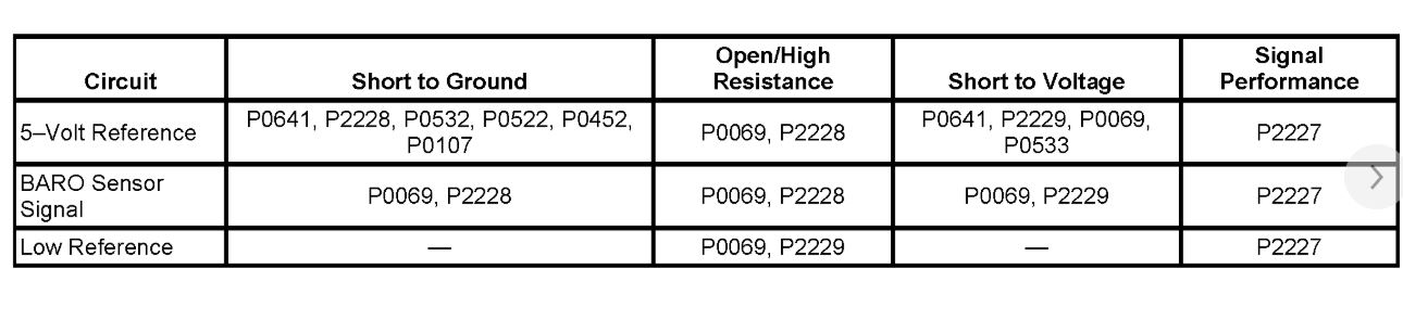
This code is for the Baro sensor but indicates a wiring issue more than a component issue. I posted the flow chart below for you to view and follow.
Roy
Circuit/System Description
The barometric pressure (BARO) sensor measures the pressure of the atmosphere. This pressure is affected by altitude and weather conditions. A diaphragm within the BARO sensor is displaced by the pressure changes that occur from varying altitudes and weather conditions. The sensor translates this action into electrical resistance. The BARO sensor wiring includes 3 circuits. The BARO sensor and all related circuits are inside the engine control module (ECM). The BARO sensor provides a signal voltage to the ECM, relative to the pressure changes on the BARO sensor signal circuit. The ECM converts the signal voltage input to a pressure value. Changes in BARO due to weather are relatively small, while changes due to altitude are significant. Pressure can range from 56 kPa at an altitude of 4,267 meters (14,000 feet), to 105 kPa at or below sea level. The BARO sensor has a range of 0-128 kPa. The ECM uses the BARO sensor input for fuel delivery and other diagnostics.
Conditions for Running the DTC
* The ignition is ON.
* DTC P2228 and P2229 run continuously when the above condition is met.
Conditions for Setting the DTC
P2228
The BARO is less than 60 kPa for 1 second
P2229
The BARO is more than 120 kPa for 1 second
Action Taken When the DTC Sets
DTCs P2228 and P2229 are Type B DTCs.
Conditions for Clearing the DTC
DTCs P2228 and P2229 are Type B DTCs.
Circuit/System Verification
Important: If DTC P0641 or P0651 are set, diagnose those DTCs first. Refer to Diagnostic Trouble Code (DTC) List - Vehicle. See: Vehicle > Initial Inspection and Diagnostic Overview
1. Ignition ON, observe the BARO parameter with a scan tool.
2. Compare the BARO value to the range specified in the altitude vs. Barometric pressure table.
The BARO parameter should be within the range specified in the altitude vs. Barometric pressure table. Refer to Altitude Versus Barometric Pressure.
Circuit/System Testing
1. Ignition OFF, disconnect the harness connector at the BARO sensor.
2. Ignition OFF, allow sufficient time for the control module to power down. Measure for less than 5 ohms of resistance between the low reference circuit of the connector and a good ground.
If greater than the specified range, test the low reference circuit for an open/high resistance. If the circuit tests normal, replace the ECM.
3. Ignition ON, test for 4.8-5.2 volts between the 5-volt reference circuit and ground.
If less than the specified range, test the 5-volt reference circuit for an open/high resistance or a short to ground. If the circuit tests normal, replace the ECM.
If greater than the specified range, test the 5-volt reference circuit for a short to voltage. If the circuit tests normal, replace the ECM.
4. Verify the scan tool BARO sensor voltage parameter is 0 kPa.
If greater than the specified range, tests the signal circuit for a short to voltage. If the circuit tests normal, replace the ECM.
5. Install a 3-amp fused jumper wire between the signal circuit and the 5-volt reference circuit. Verify the scan tool BARO sensor parameter is greater than 126 kPa.
If less than the specified range, test the sensor signal circuit for an open/high resistance or a short to ground.
6. If all circuits test normal, test or replace the faulty sensor.
Component Testing
Important: You must perform the Circuit/System Testing before proceeding with the Component Test.
1. Turn ON the ignition with the engine OFF and remove the BARO sensor.
2. Install a 3-amp fused jumper wire between the 5-volt reference terminal C of the sensor and 5-volt reference.
3. Install a jumper wire between the low reference terminal A of the sensor and ground.
4. Install a jumper wire at the signal terminal B of the BARO sensor.
5. Connect a DMM between the jumper wire from terminal B of the sensor and ground.
6. Install the J 23738-A to the BARO sensor vacuum port. Slowly apply vacuum to the sensor while monitoring the voltage on the DMM. The voltage should vary between 5.2-0 volts without any spikes or dropouts.
If the voltage is not within the specified range or is erratic, replace the BARO sensor.
Repair Instructions
Perform the Diagnostic Repair Verification after completing the diagnostic procedure. See: A L L Diagnostic Trouble Codes ( DTC ) > Verification Tests
* Programming and Relearning See: Vehicle > Programming and Relearning
* Barometric Pressure Sensor Replacement
Image (Click to make bigger)
Thursday, August 15th, 2019 AT 1:41 PM