Welcome to 2CarPros.
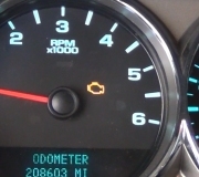
A faulty camshaft sensor can cause what you described. Interestingly, on many of these vehicles, a bad camshaft position sensor usually prevents the engine from revving over 2500 RPM's. Is that happening? Also, could you provide me with the actual code that was found?
If you plan to replace the cam sensor, here is a link that shows in general how it is done:
https://www.2carpros.com/articles/camshaft-angle-sensor-replacement
Here are the specific directions for replacement on your vehicle. Pictures 1 and 2 correlate with these directions.
______________________________________
REMOVAL
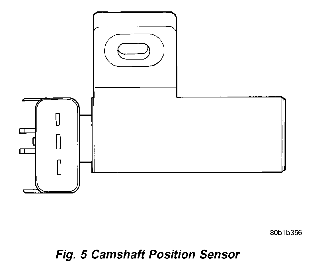
The camshaft position sensor is installed in the timing belt housing cover above the left camshaft sprocket.
1. Disconnect the negative battery cable.
2. Loosen the upper intake plenum, refer to the Intake System section.
3. Disconnect electrical connector from sensor.
4. Remove camshaft position sensor screw.
5. Pull sensor up out of the timing belt housing cover.
INSTALLATION
The camshaft position sensor is installed in the timing belt housing cover above the left camshaft sprocket.
Pic 1
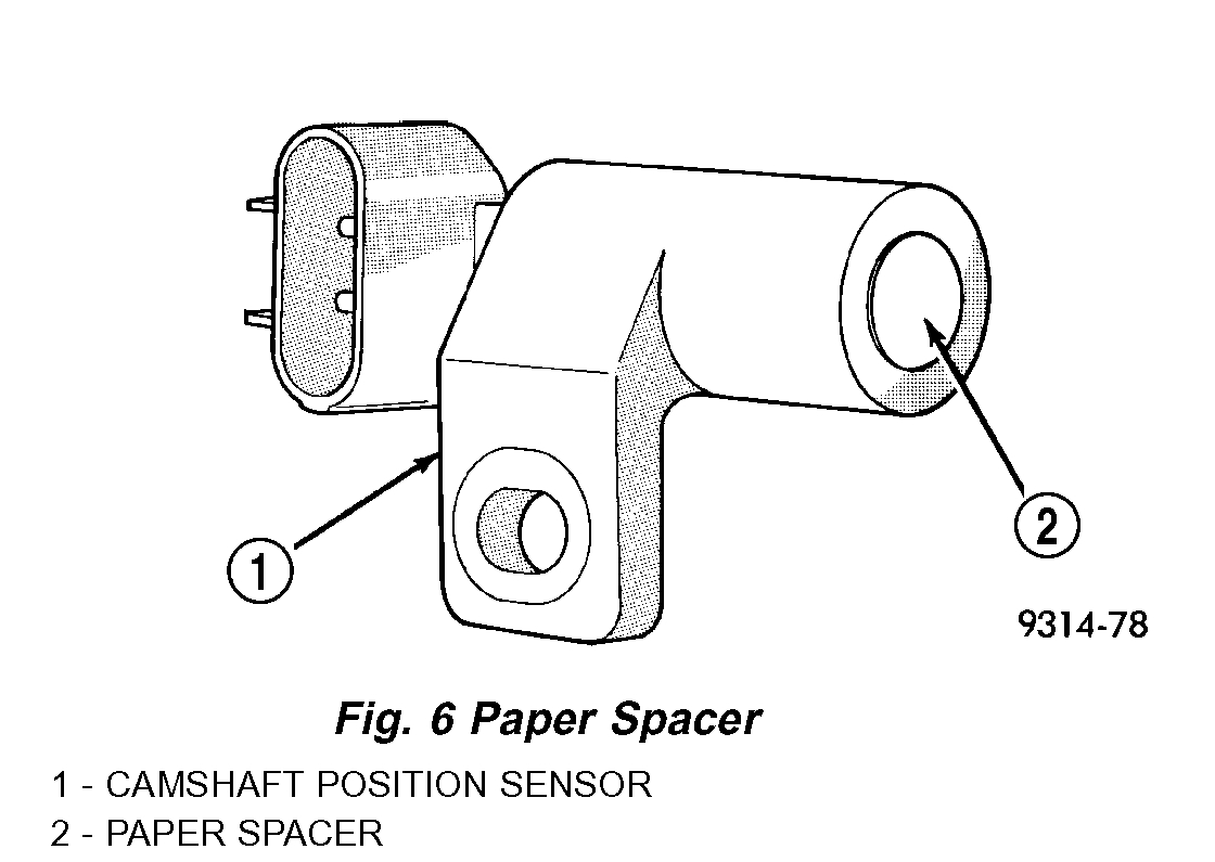
Fig. 6 Paper Spacer - 3.5L
pic 2
If the removed sensor is reinstalled, completely remove the old spacer from the sensor face. Attach a NEW SPACER to the face of the sensor before installation. If installing a new sensor, confirm that the paper spacer is attached to the face.
1. Install sensor in the timing belt housing and push sensor down until contact is made with the camshaft sprocket. While holding the sensor in this position, install and tighten the retaining bolt to 12 Nm (105 in. lbs.) torque.
2. Attach electrical connector to sensor.
3. Install the upper intake plenum, refer to the Intake System section.
4. Connect the negative battery cable.
____________________________
You will need to remove the upper intake manifold / plenum. Here are the directions for doing that.
INTAKE MANIFOLD UPPER
REMOVAL
1. Disconnect negative cable from remote jumper terminal.
pic 3
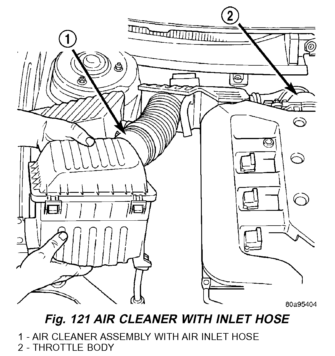
2. Disconnect the Inlet Air Temperature (IAT) Sensor connector. Remove air cleaner housing and inlet hose (Fig. 121).
3. Remove throttle and speed control cables from throttle arm and bracket.
4. Disconnect electrical connectors from the following sensors and actuators:
- Short Runner Valve (SRV) (If Equipped)
- Manifold Tuning Valve (MTV) (If Equipped)
- Throttle Position Sensor (TPS)
- Idle Air Control (IAC)
- Manifold Absolute Pressure (MAP)
5. Disconnect vacuum hoses from the following:
- Speed Control Reservoir
- Positive Crankcase Ventilation (PCV) Valve
- Proportional Purge Solenoid
- Power Brake Booster
Pic 4
Pic 5
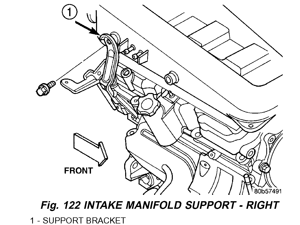
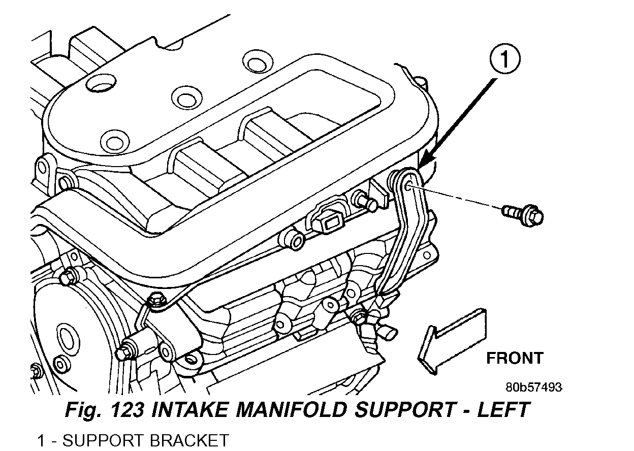
6. Remove right side (Fig. 122) and left side (Fig. 123) intake manifold supports.
pic 6
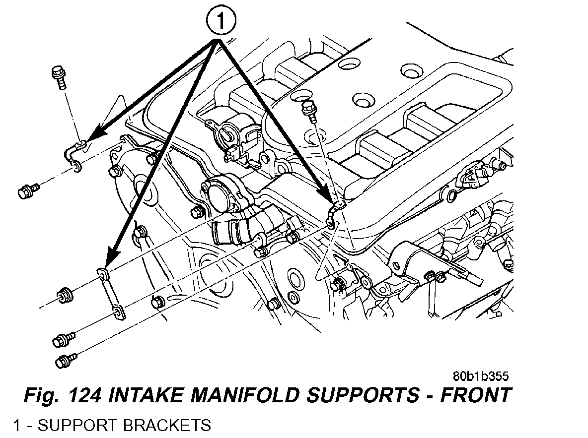
7. Remove support brackets at intake manifold front corners and at MTV (Fig. 124).
8. Loosen upper fastener attaching throttle body to support bracket.
pic 7
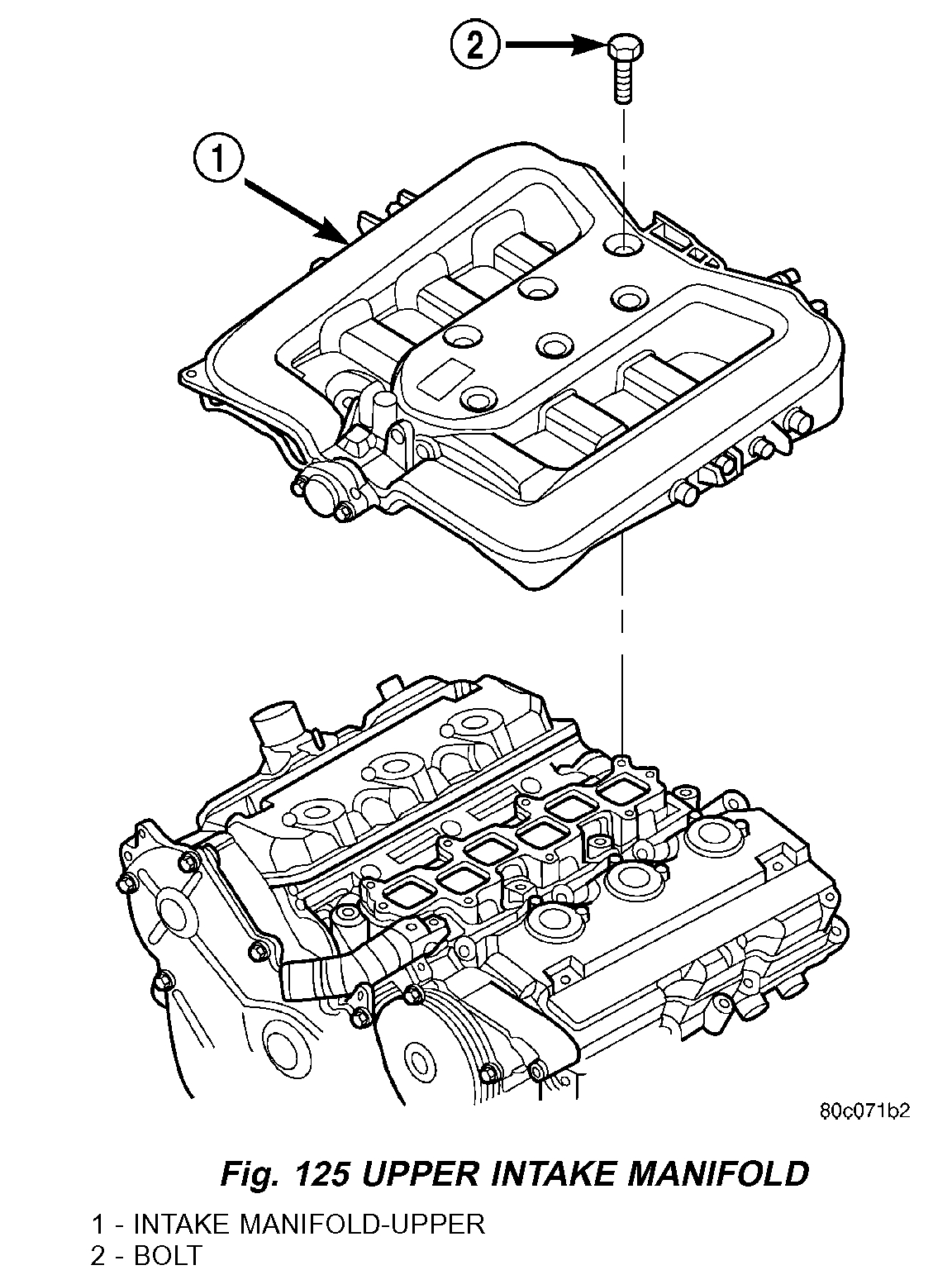
9. Remove bolts attaching intake manifold and remove manifold (Fig. 125).
INSPECTION
Check manifold for:
- Damage and cracks
- Gasket surface damage or warpage
- Damaged or clogged EGR ports
If the manifold exhibits any damaged or warped conditions, replace the manifold. Clean EGR ports as necessary.
INSTALLATION
1. Clean and inspect gasket sealing surfaces.
NOTE: Intake gaskets can be reused, provided they are free of cuts or tears.
2. Inspect gasket for cuts or tears. Replace gaskets as necessary.
3. Install intake manifold (Fig. 125) and hand start all attaching bolts.
Upper
pic 8
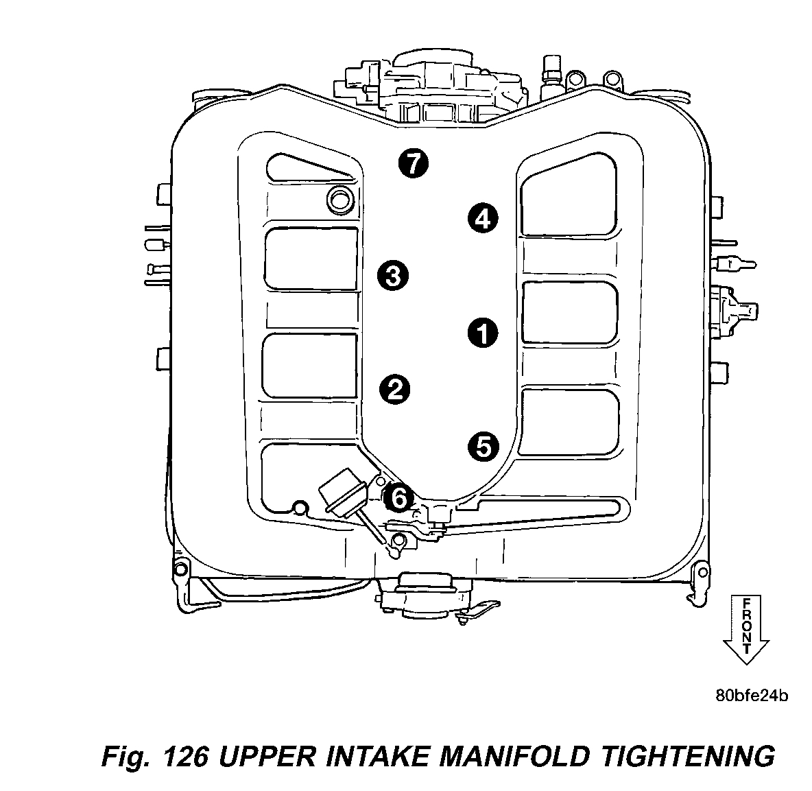
4. Tighten bolts gradually in sequence shown in (Fig. 126)until a torque of 12 Nm (105 in. lbs.) is obtained.
5. Install right side (Fig. 122) and left side (Fig. 123) intake manifold supports.
6. Install manifold support brackets at front corners and at MTV (Fig. 124).
7. Tighten fastener attaching throttle body to support bracket.
8. Connect vacuum lines to the following:
- Speed Control Reservoir
- Positive Crankcase Ventilation (PCV) Valve
- Proportional Purge Solenoid
- Power Brake Booster
9. Connect electrical connectors to the following:
- Short Runner Valve (SRV)(If Equipped)
- Manifold Tuning Valve (MTV) (If Equipped)
- Throttle Position Sensor (TPS)
- Idle Air Control (IAC)
- Manifold Absolute Pressure (MAP)
10. Install throttle and speed control cables to bracket and throttle arm.
11. Install air cleaner housing and inlet hose (Fig. 121). Connect Inlet Air Temperature (IAT) Sensor connector.
12. Connect negative cable to remote jumper terminal.
_______________________________________________-
Let me know if this helps or if you have other questions.
Take care,
Joe
Images (Click to make bigger)
Saturday, June 1st, 2019 AT 9:22 PM