1995 Buick Park Avenue Traction control system

Tiny
PART237
  • MEMBER
  • 1995 BUICK PARK AVENUE
  • 6 CYL
  • FWD
  • AUTOMATIC
  • 76,000 MILES
Tracion control (TCS) light comes on ~15mph. When car is started, "idiot" lights all come on and then extinguish. Can turn traction off and on with switch after engine start; but once it comes on while driving, cannot turn off or on with switch. The ABS light does not come on other than the normal indications at start up. Sometimes while driving the light will go off for awhile and then pops back on. As ABS and TCS both feed off of the same wheel sensors, I 'assume' that they are ok. Where should I start?
Friday, March 20th, 2009 AT 6:46 PM

6 Replies

Tiny
DAVE H
  • MECHANIC
  • 13,383 POSTS
Hello .. thanks for the donation .. much appreciated

Hope this helps .. let me know

PRE-DIAGNOSTIC INSPECTION
Before diagnosing ABS/TCS, perform a comprehensive visual inspection of system as follows.
Check ABS/TCS wiring harness connectors for looseness. Check harness routing; pay particular attention to wheel speed sensor wiring harness routing.
Check fuses No. 1D, 5B and 6B in instrument panel fuse block. Check fuses No. 1 and 2 in underhood fuse block.
Check brake fluid level in master cylinder reservoir.
Check brake fluid level in Pressure Modulator Valve (PMV) assembly reservoir.
Ensure parking brake is fully released.
Ensure parking brake switch is functioning properly.
Always perform ABS/TCS system functional check before using DIAGNOSTIC CODE CHARTS

The EBCM/EBTCM has self-diagnostic capability, which can detect system failures. Fault codes stored by EBCM/EBTCM can be displayed using Tech 1 scan tester. There are no provisions for flash code diagnostics.
Begin ABS/TCS diagnosis with PRE-DIAGNOSTIC INSPECTION procedure. If failures are found during pre-diagnostic inspection, perform necessary repairs, and proceed with ABS/TCS FUNCTIONAL CHECK. See Fig. 5 .
If no failures are found during pre-diagnostic inspection, go to ABS/TCS FUNCTIONAL CHECK. See Fig. 5 . The ABS/TCS FUNCTIONAL CHECK will either indicate ABS/TCS is functioning properly or direct technician to various diagnostic procedures such as diagnostic charts, symptom diagnosis or BRAKE warning light diagnosis.

CHART D - TRACTION OFF WARNING LIGHT ON CONTINUOUSLY & NO DTC SET (BUICK WITH UH8 OR U2A INSTRUMENT CLUSTER)
Circuit Description
When ignition switch is first turned to RUN position, EBTCM goes through a self-test, which lasts 2-4 seconds. During self-test, EBTCM commands TRACTION OFF indicator warning light on. Powertrain Control Module (PCM) can also command EBTCM to set a Code 75 which will illuminate TRACTION OFF indicator.
Traction control switch is located either on instrument panel center trim plate or driver's front door trim panel. Switch allows driver to select traction control mode (on/off). When traction control system is turned off, TRACTION OFF warning light comes on.
EBTCM monitors transaxle temperature through information provided by PCM. When transaxle becomes hot, about 320 °F (160 °C), EBTCM disables traction control system and turns on TRACTION OFF warning light. This allows brakes and transaxle to cool down.
When transaxle cools to 300 °F (149 °C), EBTCM keeps TRACTION OFF warning light on and disables traction control for an additional 3-5 minutes to allow sufficient cooling.
Diagnostic Aids
Check for short to ground in circuit No. 800 (Tan wire), circuit No. 1050 (Black or Black/White wire) and circuit No. 1571 (Brown/White wire). Check for faulty traction control switch or EBTCM.
NOTE:With traction control (if equipped), any symptom lighting ANTI-LOCK warning light will also light TRACTION OFF warning light. When both warning indicators are on, perform ANTI-LOCK warning light diagnosis if no DTC is set.


https://www.2carpros.com/forum/automotive_pictures/266999_AAA2_332.png

Was this
answer
helpful?
Yes
No
Friday, March 20th, 2009 AT 9:07 PM
Tiny
PART237
  • MEMBER
  • 3 POSTS
Thanks for the info. Unfortunatly I don't have a 'tech 1' scanner, and at 3K for one..
Your reply refers to figure 5. What is that?
I do appreciate your assitance with this.
Thanks
Was this
answer
helpful?
Yes
No
Monday, March 23rd, 2009 AT 12:09 PM
Tiny
DAVE H
  • MECHANIC
  • 13,383 POSTS
Hello.

Figure 5 is a breakdown of the diagnostic procedures. which is why i did not put it in the last post .. it is basically telling you to do the preliminary checks in the first part of my last post and then have the vehicle plugged into a TECH scanner !!


https://www.2carpros.com/forum/automotive_pictures/266999_tech_1.jpg


If you right click your mouse on figure 5 you should be able to save it to your computer and enlarge to read it better .. if you have done the visual check of the system most repair shops will be able to read the codes for you !!

hope this helps .. let me know


https://www.2carpros.com/forum/automotive_pictures/266999_AAA2_370.png

Was this
answer
helpful?
Yes
No
Monday, March 23rd, 2009 AT 12:38 PM
Tiny
DAVE H
  • MECHANIC
  • 13,383 POSTS
Hello.

I did also find this TSB that may be of interest to you ..!!

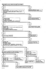
"ANTILOCK"/"TRACTION OFF" LIGHT STAYS ON - CODE 61
TECHNICAL SERVICE BULLETIN
Reference Number(s): 53-50-17

Related Ref Number(s): 53-50-17
ARTICLE BEGINNING
AMBER ANTILOCK WARNING LIGHT AND (IF EQUIPPED) AMBER TRACTION OFF WARNING LIGHT STAYS ON (APPLY SEALANT/GREASE)
Model(s): 1995 Buick LeSabre, Park Avenue; 1995 Oldsmobile Ninety Eight, Eighty Eight; 1995 Pontiac Bonneville
Bulletin No.: 5 - Brakes
Section: 53-50-17
Date: February, 1996
MODELS AFFECTED
1995 Pontiac Bonneville Built Prior to June 1, 1995.
CONDITION
Some owners may comment that the amber antilock warning light and (if equipped) amber traction off warning light stays on. Also, the antilock brake system and (if equipped) traction control system may become inoperative. The following conditions will occur:
Amber antilock warning light and (if equipped) amber traction off warning light turns on and stays on. The red brake warning light stays off.
EBTCM Diagnostic Trouble Code (DTC) 61 will be set.
NOTE:THIS CONDITION IN NO WAY AFFECTS THE OPERATION OF THE POWER BRAKES.

CAUSE
Fluids trapped in the wire harness in the area below the windshield washer reservoir. This allows the fluids to come in contact with the ground splice for the Pressure Modulator Valve (PMV) motor (S129) and to be wicked down CKT 1150 to the 4-way brake PMV connector C2. Sufficient fluids in the connector interfere with the pump run signal, causing a DTC 61 to set. This condition DOES NOT damage the Electronic Brake Traction Control Module (EBTCM).
CORRECTION
Seal splice S129 with electrical moisture sealant, P/N 11515174. Cut sealant into approximately a 2" x 2" square. Position seam in flexible conduit down or slit the bottom of the conduit in area of splice S129 and apply electrical connector grease, P/N 12377900, to terminals in connector C2.
PROCEDURE
Remove air cleaner and windshield washer reservoir. For 3800 super charged engines, if equipped, remove the auto level control air compressor.
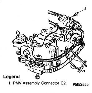
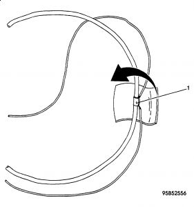
Remove flexible conduit covering the main harness 6 inches in both directions from the point where the wires break out to the PMV motor connector C2. See Fig. 1 .
Locate splice S129 and remove the tape covering it. See Fig. 2 . It is located about 2 inches forward from the point where the wires break out of the wiring harness for the connector C2.
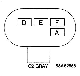
Open connector C2.
CAUTION:TO PREVENT PERSONAL INJURY, WEAR HEARING AND EYE PROTECTION FOR THE NEXT STEP.

Using compressed air and a blow gun, blow air down terminal E on the harness side of connector C2 until no fluid can be seen being expelled from the wire at S129. See Fig. 3 . This will take several minutes.
Thoroughly dry splice S129 and the wires 2 inches in both directions.
Thoroughly clean the wires 2 inches in both directions of splice S129 with an alcohol wipe (available locally) and allow to completely dry.
Cut a 2" x 2" piece of electrical moisture sealant. Apply the moisture sealant patch to the splice by folding it over the wires. Make sure that there is at least a 1/8 inch gap between any parallel wires to ensure that the patch can seal between the wires. See Fig. 4 . Press the patch together with your fingers or duck bill pliers, making sure that the wires are completely sealed.
Return the harness to its original condition, making sure that the conduit seam in the area of the splice is on the bottom of the harness or slit the bottom of the conduit and make sure that any tape used to secure the conduit will allow any trapped fluids to drain.
Using a brush such as an acid brush (available locally), thoroughly coat both the male and female terminals of connector C2 with the electrical connector grease.
Reconnect connector C2 and reassemble the washer fluid reservoir, air cleaner and, if necessary, the electronic level control pump.


https://www.2carpros.com/forum/automotive_pictures/266999_1_17.jpg


https://www.2carpros.com/forum/automotive_pictures/266999_2_15.jpg


https://www.2carpros.com/forum/automotive_pictures/266999_3_17.jpg


https://www.2carpros.com/forum/automotive_pictures/266999_4_13.jpg


Hope this helps .. let me know


https://www.2carpros.com/forum/automotive_pictures/266999_AAA2_371.png

Was this
answer
helpful?
Yes
No
+1
Monday, March 23rd, 2009 AT 12:46 PM
Tiny
PART237
  • MEMBER
  • 3 POSTS
I checked the connectors, no joy. Broke down and had the local dealer pull the codes. Found a DTC 74 code. In a further fit of despiration, ordered the complete shop manuals from Helm. Lo and behold, there is a seperate supplimental manual for the ABS/Traction control. So Meter in hand, I'm starting the checks. Hopefully it will all pan out.
Thanks for your assistance; will post if/when I get this puppy figured out.
Was this
answer
helpful?
Yes
No
Wednesday, March 25th, 2009 AT 4:07 PM
Tiny
DAVE H
  • MECHANIC
  • 13,383 POSTS
DTC 74 - PRESSURE MODULATOR VALVE (PMV) PRESSURE SWITCH CIRCUIT OPEN OR SHORTED
Circuit Description
Pressure switch monitors primary brake system pressure. Normally closed brake switch opens when brakes are applied (pressure exceeds 101 psi). If brakes are manually applied during traction control mode (if equipped), Pressure Modulator Valve (PMV) pressure switch input and brake switch input signal EBCM/EBTCM to disable traction control and allow manual braking. Pressure switch is part of PMV assembly and is not serviceable.
Test Description
DTC 74 will set if EBCM/EBTCM detects open or short to ground in PMV pressure switch circuit.
Diagnostic Aids
Check for open in circuit No. 853 (Light Blue/Black wire) and circuit No. 1659 (Light Blue wire). Check for short to ground in circuit No. 1659 (Light Blue wire) with brakes applied. Check for PMV pressure switch failure.
Fig. 54: DTC 74 Schematic
Courtesy of GENERAL MOTORS CORP.
Fig. 55: DTC 74 Flow Chart (1 Of 3)
Courtesy of GENERAL MOTORS CORP.
Fig. 56: DTC 74 Flow Chart (2 Of 3)
Courtesy of GENERAL MOTORS CORP.
Fig. 57: DTC 74 Flow Chart (3 Of 3)
Courtesy of GENERAL MOTORS CORP.

Let me know if you need any of the diagrams listed !!


https://www.2carpros.com/forum/automotive_pictures/266999_AAA2_392.png

Was this
answer
helpful?
Yes
No
Wednesday, March 25th, 2009 AT 7:48 PM

Please login or register to post a reply.

Sponsored links