Hi and thanks for using 2CarPros.com.
Here are general directions for replacing rear brakes and rotors:
https://www.2carpros.com/articles/how-to-replace-rear-brake-pads-and-rotors
Here are the directions specific to your vehicle. All attached pictures correlate with these directions.
___________________________
Brake Pads Replacement - Rear
Brake Pads Replacement - Rear
Caution: Refer to Brake Dust Caution in Cautions and Notices.
Removal Procedure
1. Inspect the fluid level in the brake master cylinder reservoir.
2. If the brake fluid level is midway between the maximum-full point and the minimum allowable level, no brake fluid needs to be removed from the reservoir before proceeding.
3. If the brake fluid level is higher than midway between the maximum-full point and the minimum allowable level, remove brake fluid to the midway point before proceeding.
4. Raise the vehicle and suitably support. Refer to Lifting and Jacking the Vehicle in General Information.
5. Remove the tire and wheel assembly. Refer to Tire and Wheel Removal and Installation in Tires and Wheels.
Notice: When using a large C-clamp to compress a caliper piston into a caliper bore of a caliper equipped with an integral park brake mechanism, do not exceed more than 1 mm (0.039 in) of piston travel. Exceeding this amount of piston travel will cause damage to the internal adjusting mechanism and/or the integral park brake mechanism.
6. Using a large C clamp, compress the brake caliper piston into the brake caliper bore to gain enough clearance to allow the brake caliper to pivot off the brake caliper bracket. Compress the piston until resistance is felt, but no more than 1 mm (0.039 in) of piston travel.
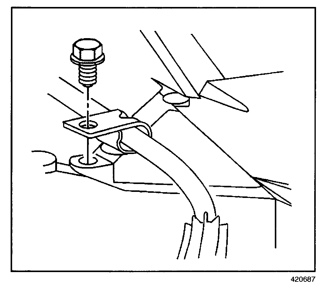
7. Remove the park brake cable guide bolt from the lower control arm.
8. Remove the bottom brake caliper pin bolt.
Notice: Support the brake caliper with heavy mechanic's wire, or equivalent, whenever it is separated from it's mount and the hydraulic flexible brake hose is still connected. Failure to support the caliper in this manner will cause the flexible brake hose to bear the weight of the caliper, which may cause damage to the brake hose and in turn may cause a brake fluid leak.
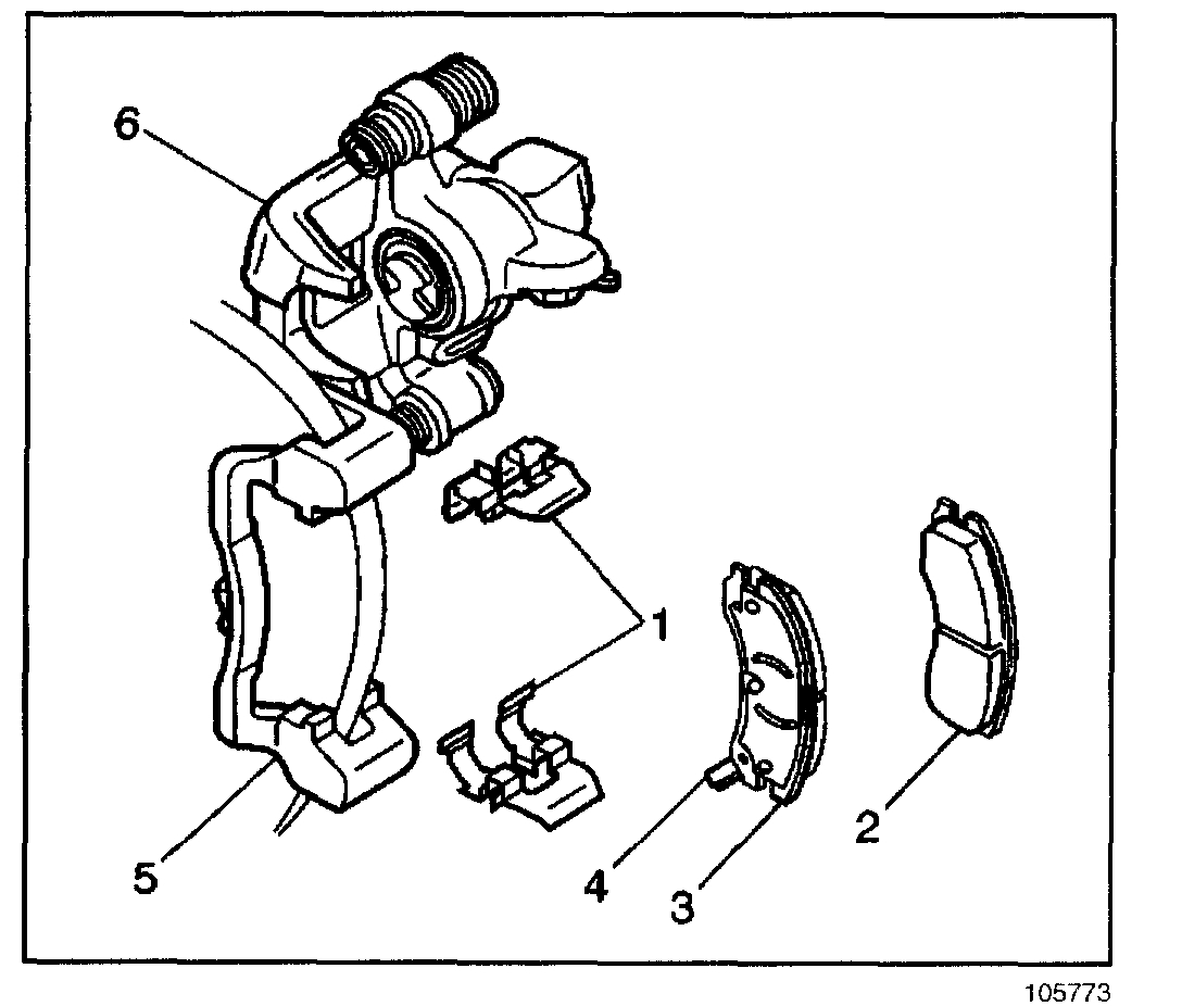
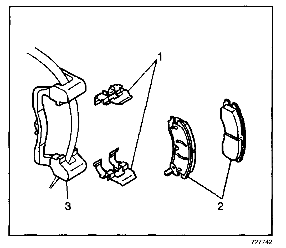
9. Pivot the brake caliper body (6) upward and secure out of the way with heavy mechanic's wire. Do NOT disconnect the hydraulic brake flexible hose from the caliper.
10. Remove the inboard (2) and outboard (3) brake pads from the brake caliper bracket (5).
11. Remove and inspect the brake pad retainers (1).
Installation Procedure
1. Inspect the brake caliper bolt suspension boots for cuts, tears, or deterioration. If damaged, replace the brake caliper pin boots.
2. Inspect the brake caliper pin bolts for damage or corrosion. Replace if damaged or corroded. Do not attempt to clean away corrosion. Corrosion is typically caused by damaged pin boots. Refer to Disc Brake Mounting and Hardware Inspection - Rear. See: Disc Brake System > Component Tests and General Diagnostics > Inspection - Rear
3. Inspect the brake caliper piston boot for deterioration, repair or replace the brake caliper if damaged. Refer to Brake Caliper Replacement - Rear. See: Brake Caliper > Procedures > Brake Caliper Replacement - Rear
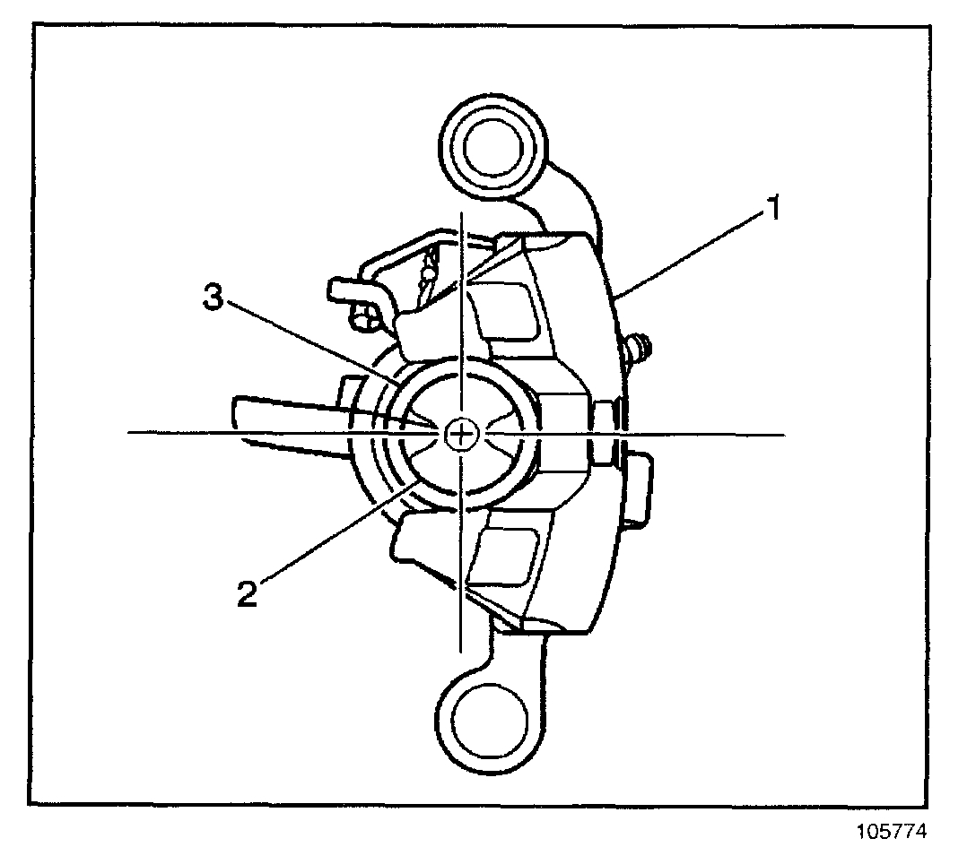
4. Retract the brake caliper piston (2) into the brake caliper bore. Use a spanner type wrench to turn the piston (2) clockwise until it bottoms in the brake caliper bore and align the piston.
5. Align the cutouts in the brake caliper piston to the alignment pins on the brake pads.
6. Apply a thin coat of high temperature silicone lube to the rear brake caliper bolts.
7. Install the brake pad retainers (1) into the brake caliper bracket (5).
8. Install the inboard (2) and outboard (3) brake pads into the brake caliper bracket.
9. Pivot the brake caliper down over the brake pads and into the brake caliper bracket.
Notice: Refer to Fastener Notice in Cautions and Notices.
10. Insert the lower brake caliper pin bolt.
Tighten
Tighten the brake caliper pin bolt to 27 N.m (20 lb ft).
11. Install the park brake cable guide bolt to the lower control arm.
Tighten
Tighten the park brake cable guide bolt to 24 N.m (18 lb ft).
12. Install the tire and wheel assembly. Refer to Tire and Wheel Removal and Installation in Tires and Wheels.
13. Lower the vehicle.
14. With the engine OFF, gradually apply the brake pedal to approximately 2/3 of its travel distance.
15. Slowly release the brake pedal.
16. Wait 15 seconds, then repeat steps 1-15 until a firm brake pedal is obtained. This will properly seat the brake caliper pistons and brake pads.
17. Fill the brake master cylinder reservoir to the proper level. Refer to Master Cylinder Reservoir Filling in Hydraulic Brakes.
18. Burnish the pads and rotors. Refer to Burnishing Pads and Rotors. See: Brake Pad > Procedures > Burnishing Pads and Rotors See: Brake Master Cylinder > Procedures > Master Cylinder Reservoir Filling
_____________________
Brake hardware replacement if needed:
DISC BRAKE HARDWARE REPLACEMENT- REAR
Disc Brake Hardware Replacement - Rear
Caution: Refer to Brake Dust Caution in Cautions and Notices.
Notice: Support the brake caliper with heavy mechanic's wire, or equivalent, whenever it is separated from it's mount and the hydraulic flexible brake hose is still connected. Failure to support the caliper in this manner will cause the flexible brake hose to bear the weight of the caliper, which may cause damage to the brake hose and in turn may cause a brake fluid leak.
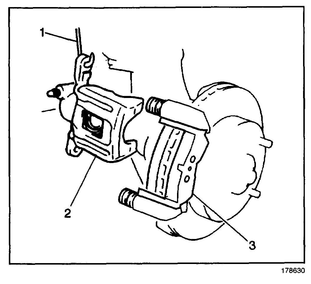
1. Remove the brake caliper from the mounting bracket and support the brake caliper (2) with heavy mechanic's wire (1), or equivalent; do NOT disconnect the hydraulic brake flexible hose from the caliper. Refer to Brake Caliper Replacement - Rear. See: Brake Caliper > Procedures > Brake Caliper Replacement - Rear
2. Remove the brake pads (2) from the brake caliper bracket (1).
3. Remove the brake pad retainers (1) from the brake caliper bracket (3).
4. Remove the brake caliper bracket (3). Refer to Brake Caliper Bracket Replacement - Rear. See: Brake Caliper > Procedures > Brake Caliper Bracket Replacement
5. Mount the brake caliper bracket (3) in a vise.
6. Clean all parts in clean, denatured alcohol.
7. Dry with low pressure, non-lubricated, filtered air.
8. Inspect the brake caliper bracket for cracks. If cracked, replace bracket.
9. Lubricate the brake caliper pin bolt sleeves with a thin coat of high temperature silicone lube.
10. Install the brake caliper bracket. Refer to Brake Caliper Bracket Replacement - Rear.
11. Install the brake pad retainers (1) to the bracket caliper bracket (3).
12. Install the brake pads (2) to the bracket caliper bracket (3).
13. Install the brake caliper to the brake caliper bracket.
_________________________________________
Brake Rotor Replacement
Brake Rotor Replacement - Rear
Tools Required
J 41013 Rotor Resurfacing Kit
J 42450-A Wheel Hub Resurfacing Kit
Caution: Refer to Brake Dust Caution in Service Precautions.
Removal Procedure
1. Raise and support the vehicle. Refer to Lifting and Jacking.
2. Remove the tire and wheel assembly.
3. Install a C-clamp over the body of the brake caliper, with the C-clamp ends against the rear of the caliper body and the outboard disc brake pad.
4. Using the C-clamp, compress the piston into the caliper bore just enough to allow the caliper to slide away from the rotor.
5. Remove the C-clamp.
Notice: Support the brake caliper with heavy mechanic's wire, or equivalent, whenever it is separated from its mount and the hydraulic flexible brake hose is still connected. Failure to support the caliper in this manner will cause the flexible brake hose to bear the weight of the caliper, which may cause damage to the brake hose and in turn may cause a brake fluid leak.
6. Remove the brake caliper and bracket from the vehicle, support the caliper assembly away from the rotor. Refer to Brake Caliper Bracket Replacement - Rear.
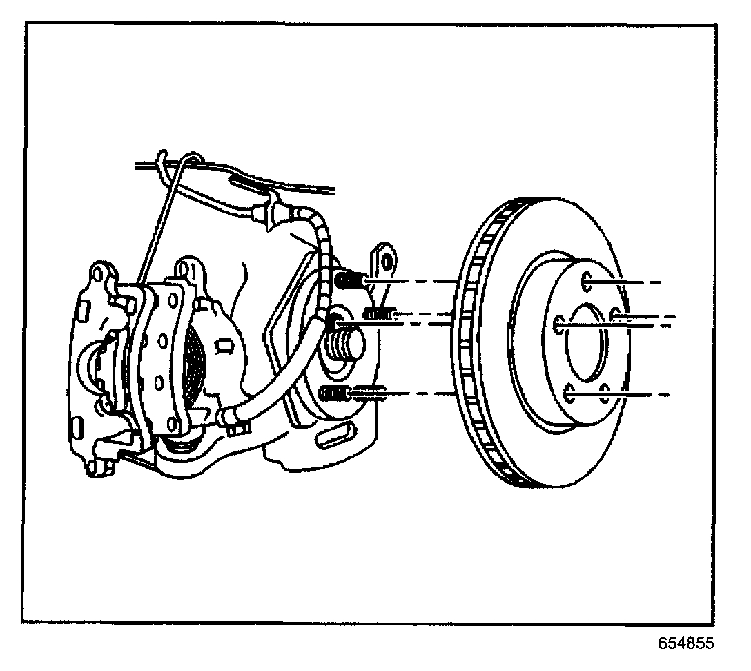
7. Mark the relationship of the rotor to the hub.
8. Remove the brake rotor.
Installation Procedure
Important: Whenever the rotor has been separated from the wheel bearing flange, clean any rust or contaminants from the wheel bearing flange and the brake rotor mating surfaces. Failure to do this may result in increased lateral runout (LRO) of the brake rotor, and brake pulsation.
1. Use the J 42450-A, thoroughly clean any rust or corrosion from the mating surface of the hub/axle flange.
2. Use the J 41013, thoroughly clean any rust or corrosion from the mating surface and mounting surface of the brake rotor.
3. Inspect the mating surfaces of the hub/axle flange and the rotor to ensure that there are no foreign particles or debris remaining.
4. Install the brake rotor to the hub/axle flange. Use the matchmark made prior to removal for proper orientation to the flange.
5. If the brake rotor was removed and installed as part of a brake system repair, measure the assembled LRO of the brake rotor to ensure optimum performance of the disc brakes. Refer to Brake Rotor Assembled Lateral Runout (LRO) Measurement.
6. If the brake rotor assembled LRO measurement exceeds the specification, bring the LRO to within specifications. Refer to Brake Rotor Assembled Lateral Runout (LRO) Correction.
7. Install the brake caliper and bracket assembly. Refer to Brake Caliper Bracket Replacement - Rear.
8. Install the tire and wheel assembly.
9. Lower the vehicle.
10. If the brake rotor was refinished or replaced, or if new brake pads were installed, burnish the pads and rotors. Refer to Burnishing Pads and Rotors .
________________________________
Let me know if this helps or if you have other questions.
Take care,
Joe
Images (Click to make bigger)
Tuesday, September 4th, 2018 AT 6:46 PM