Brake lights do not turn on after changing light bulbs?

Tiny
P1PTOPIA
  • MEMBER
  • 2013 HYUNDAI ELANTRA
  • 4 CYL
  • 2WD
  • AUTOMATIC
  • 110,009 MILES
My third light works and my signal light blinker work and my fuses in engine and underneath the dash check out. I even pried on the connector brass so to make sure the bulbs are making contact with the bulbs, and I still can’t get the light to work when I press on the brake. Is there a possibility you can share a wiring schematic so I can see what wires do what?
Saturday, October 1st, 2022 AT 9:20 AM

24 Replies

Tiny
AL514
  • MECHANIC
  • 4,108 POSTS
Hello, yes, we can get the wiring diagrams for you. Is this the Elantra Coupe, or GT sub-model? And is it just the Brake lamps on both sides not working? And did this start happening after changing the bulbs? What was the reason for changing the bulbs out if they were working?
Since your 3rd Brake lamp works, your issue is going to be in this connector or from the connector down the circuit to the brake lamps. This connector is located on the left (driver side) in front of the trunk. The Brake Lamp signal comes into this connector then branches out to all the brake lamps from there. It can't be a Ground issue because the turn signal, third brake lamp, and taillights all share a Ground, unless you have the setup in the third diagram which is the OEM manufactures diagram where it shows a defrost associated with the third brake lamp in which it has its own ground. Thats the only difference.

https://www.2carpros.com/articles/how-to-use-a-test-light-circuit-tester

https://www.2carpros.com/articles/how-to-use-a-voltmeter
Was this
answer
helpful?
Yes
No
Saturday, October 1st, 2022 AT 11:17 AM
Tiny
P1PTOPIA
  • MEMBER
  • 13 POSTS
I was able to unplug the connector and use a test light I had the blinker going and I had the brake pressed and as soon as I touched the male with test light it was blinking the same with the brake so it looks like I will need a new wiring plug. Would you agree? All my lights went out including the third light, so I replaced all of my lights because they were all blown out.
Was this
answer
helpful?
Yes
No
Saturday, October 1st, 2022 AT 3:05 PM
Tiny
AL514
  • MECHANIC
  • 4,108 POSTS
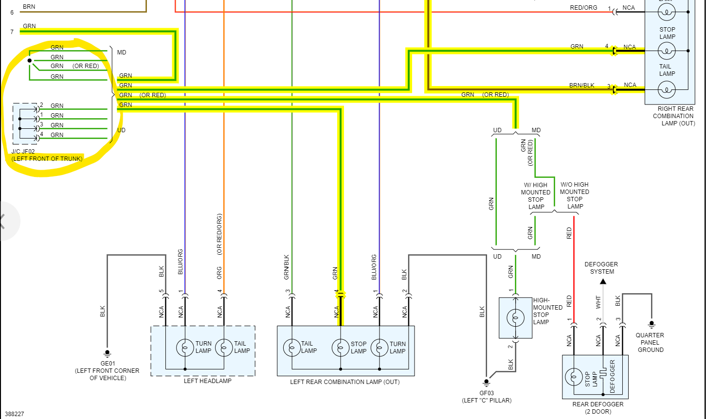
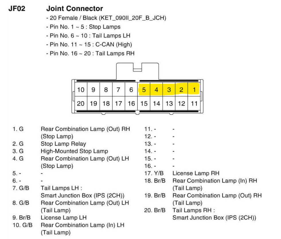
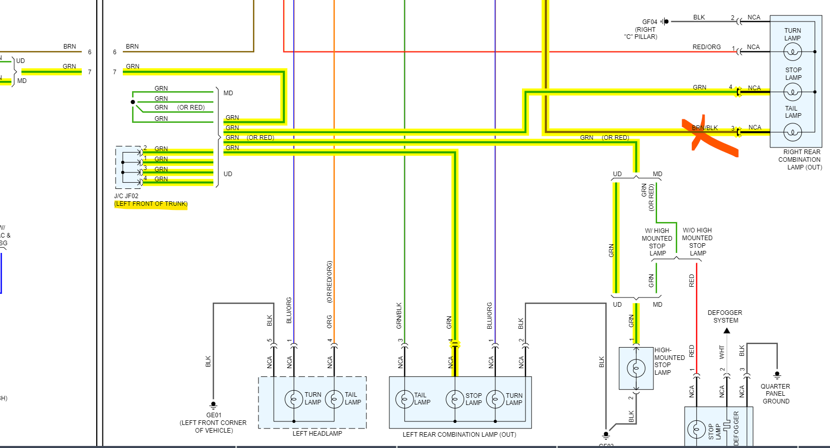
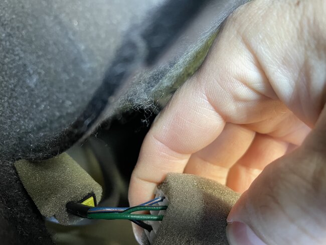
Do you mean that all the bulbs in the rear of the vehicle went out all at the same time? And just so I understand you correctly, you had the Jf02 connector unplugged, were you using the test light in series with the connector, or did you have the test light hooked to a body ground location, and just touching the pins one by one? This Joint connector has 5 pins that are linked together for the brake lights, 1 of those pins is the input and the other 4 are the output pins. But it also does the same for the 4 tail, 2 license plates with 1 feed wire. But it doesn't appear that the Turn signals come through this connector, if you notice pins 11 to 15 says c-can(high), those are computer network data wires. And Im sorry for the delay, but this is a complicated set up. I don't think you need to replace that joint connector unless it is full of corrosion. If the pins are clean. Then we have something else going on here. It doesn't look like you should have any Turn signals at those pins. Unless it's feeding back through one of the shared ground connections.
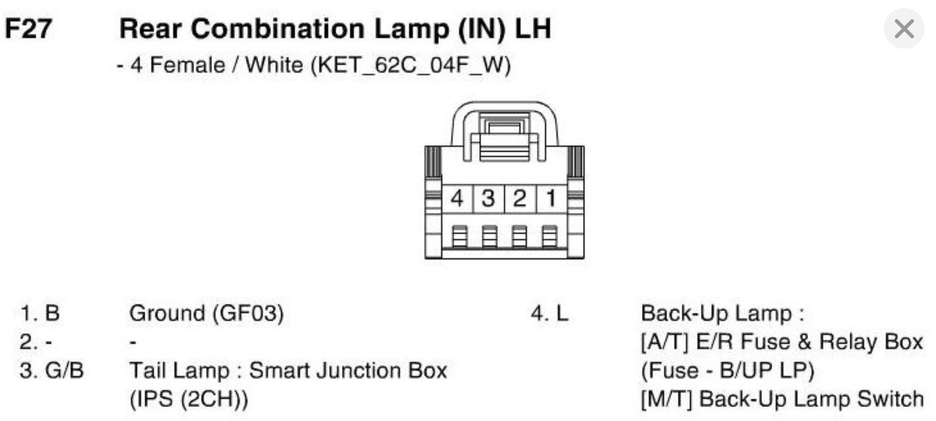
From the Joint connection diagram can you tell me what pins are giving you a turn signal flash? And also explain a bit about the bulbs burning out, did they all burn out at once and when you replaced them, did you look at the bulb and could see the actual filament burnt inside the bulb? I know it's a lot to ask. But if they all stopped working at the same time, that points to some other type of failure.
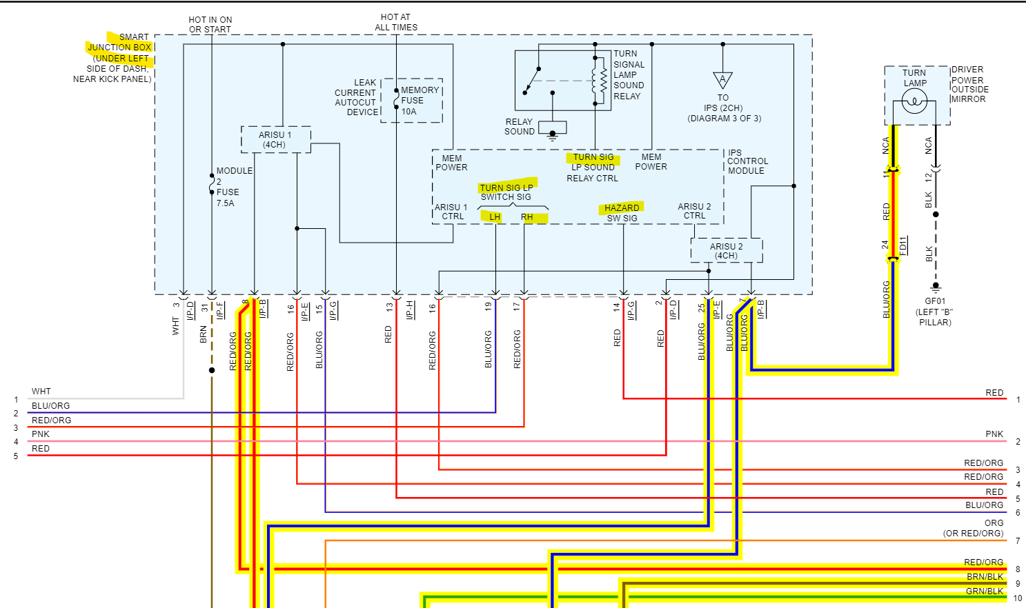
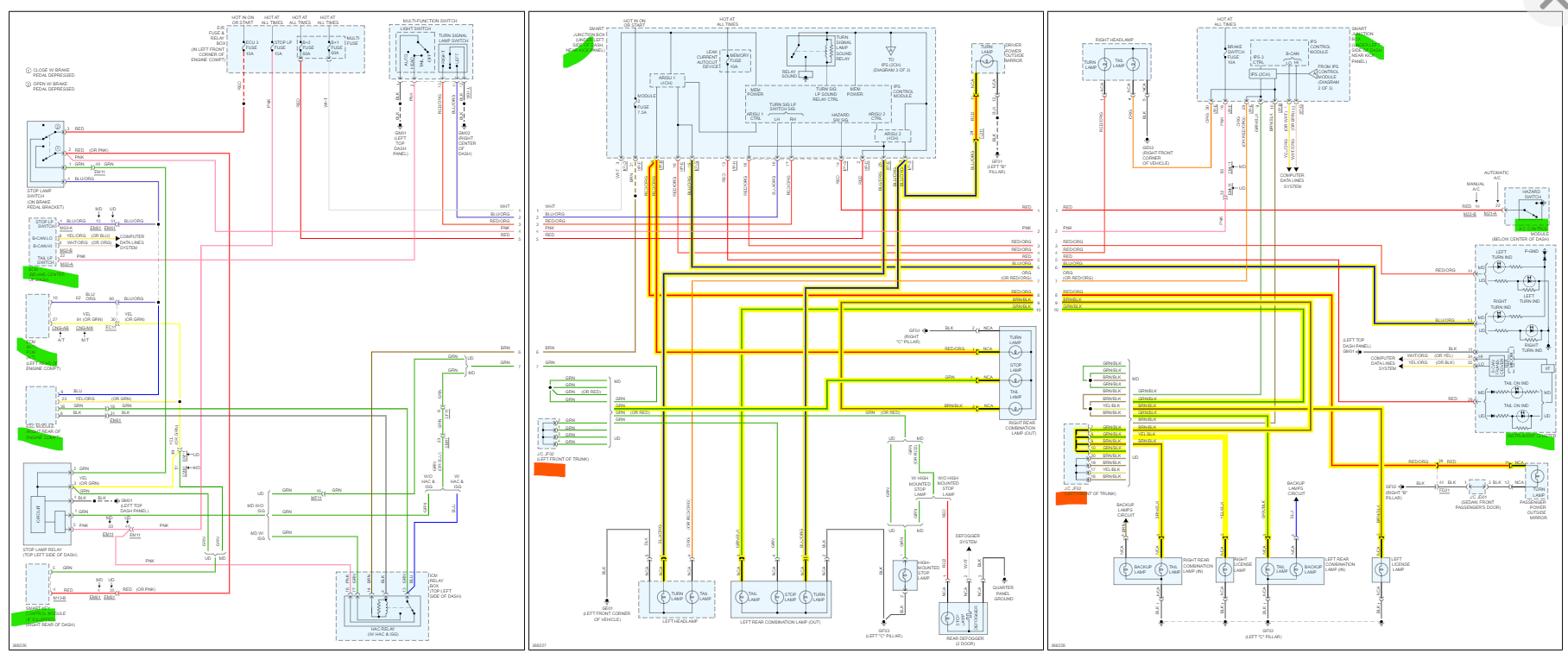
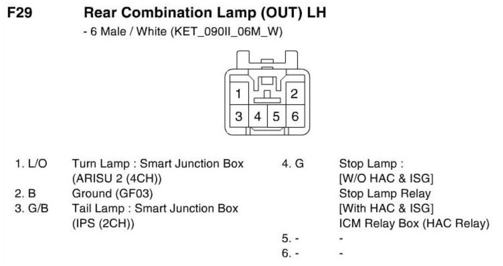
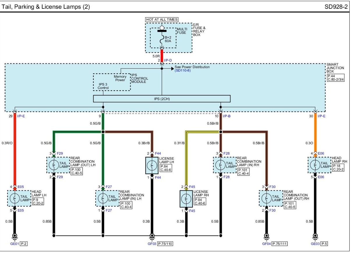
On another diagram I'm looking at the Turn Signals come from the Smart Junction Box (2nd diagram) on the driver side dash. And they don't go through that connector.
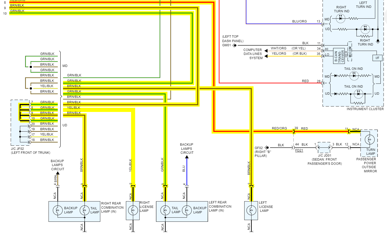
Another thing is that the Body Control Module, the Powertrain control module, the Instrument Cluster, the AC control module, Electronic Steering module, and a couple of these Smart Junction boxes are all part of the exterior lighting system and communicate together on the can-c network bus.
So, if all the lights quit together at the same time, I don't think it was just a matter of bulbs burning out all at once.
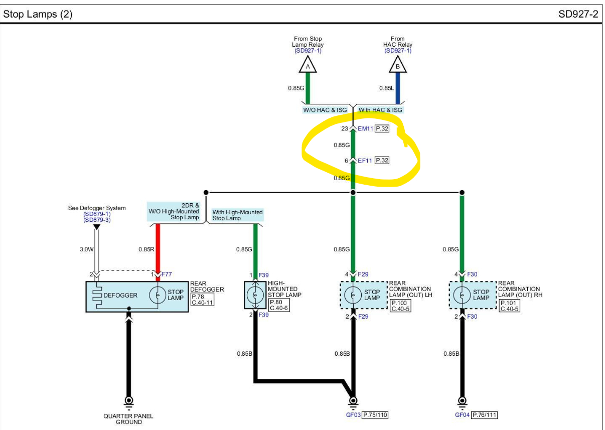
The 3rd diagram shows just the exterior lighting system and every green mark is a module(computer) and the reddish mark is that connector.
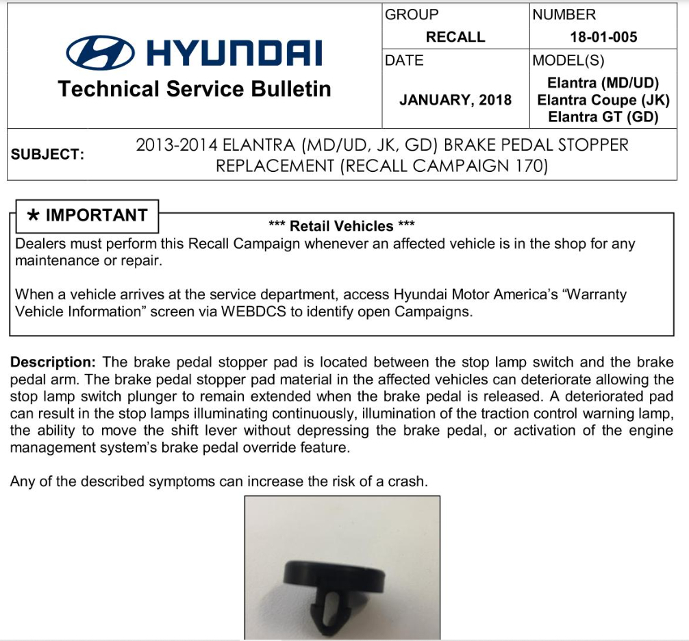
I'm going to go through and look for any Technical Bulletins on this as well.

Looking back at your last post saying they were all blown out, you may want to check the Alternator at this point to make sure there are no diodes inside that have failed and allowing any AC voltage ripple through the system.
Was this
answer
helpful?
Yes
No
Saturday, October 1st, 2022 AT 4:25 PM
Tiny
P1PTOPIA
  • MEMBER
  • 13 POSTS
I can’t say for sure that all the lights blew out at the same time. I just happened to notice that when I replaced the brake light bulbs, they didn’t work. I started going through the rest of the light bulbs thinking the circuit somehow was broken and that’s how I ended up changing all of them. My lights work, turn signals work and my reverse lights work along with my middle light. I did have the test light grounded and the ignition on. The gray wire I believe is to the brake light that did not come on when I probed it as well as the turn signal. When I unplugged the connector, I was touching the pins one by one and the lights were coming on just two of pins though I will send pics tomorrow.
Was this
answer
helpful?
Yes
No
-1
Saturday, October 1st, 2022 AT 6:29 PM
Tiny
AL514
  • MECHANIC
  • 4,108 POSTS
With the JF02 connector the feed from the Brake lamp relay will be pin 2. So, with the connector plugged in if you were to back probe the connector to check for voltage getting to the connector and then through it, you should have battery power 12v on pins 1 to 5 with the brake pedal depressed. With the tail/marker lights on you should have 12v on pins 6 to 10 for the left side and then also pins 16 to 20 for the right side. Pins 11 to 15 is the c-can bus and that will have a bias voltage of 2.5v. If using a multimeter, you might catch the can bus wires jumping up to 3.5v extremely briefly if at all because of how fast the data packets travel on the network.
But if you back probe the connector plugged in and you're getting the correct voltage readings on all the wires, then we will know that voltage is at least reaching that point. And using a multimeter the best thing to do is do a voltage drop test from the connector to the brake light bulb socket and see if there's a loss of voltage anywhere from the connector to the brake light assembly. Checking when the lights are on is the proper way to check because the circuit will be loaded at that point and carrying current. I'm going to try to find out what the data wires are for in that connector. I believe c-can is medium speed used for body and chassis controls.
But check the plug connected and see what you have there. Use a multimeter if you have one. If not, you only need a basic meter that can read dc volts up to 20v. You can get a meter cheap, about twenty dollars or less.
Was this
answer
helpful?
Yes
No
Saturday, October 1st, 2022 AT 7:25 PM
Tiny
P1PTOPIA
  • MEMBER
  • 13 POSTS
I was able to take a reading on the connector and on the three-color wires I got at least 12v but the black wire there was only.03v

On the socket in the middle, I got a reading of 12v but on the side where the black wire goes I got a reading of.03. The lights were on, and the brake was on too.
Was this
answer
helpful?
Yes
No
-1
Sunday, October 2nd, 2022 AT 10:49 AM
Tiny
AL514
  • MECHANIC
  • 4,108 POSTS
It looks like all the black wires are Grounds, so you would read about 0.3v on an active ground wire. So out of the 20 wires in this connector can you tell me which pin numbers had 12v? There are a few wires at the joint connector that are Brown with a Black stripe which might be had to see, and some wiring diagrams are not exactly correct, but all the grounds on this car are black wires. Are you getting any voltage reading at the bulb sockets themselves in the rear of the vehicle? And is everything out in the rear except the third brake light?
Looking at this diagram, the jf02 actually has the wires numbered, you can 2, 1, 3, 4. Those are the pins on that connector, and these are strictly the Brake light circuits. Granted the wire might not be green, it says they can be Red too. But these pins should all have 12v. And the pin 5 might be a ground (black wire), since it's not listed at the connector right there. It looks like pin 3 is your third brake light too, the high mounted lamp. Ignore the wire that has a red X on it, the program highlighted that by itself for some reason.
Was this
answer
helpful?
Yes
No
-1
Sunday, October 2nd, 2022 AT 12:04 PM
Tiny
P1PTOPIA
  • MEMBER
  • 13 POSTS
I got 12 v in the socket, lights work so does the turn signals.
Was this
answer
helpful?
Yes
No
-1
Sunday, October 2nd, 2022 AT 12:14 PM
Tiny
AL514
  • MECHANIC
  • 4,108 POSTS
Okay, so are you just wondering why they all went out at the same time?
Was this
answer
helpful?
Yes
No
Sunday, October 2nd, 2022 AT 12:20 PM
Tiny
P1PTOPIA
  • MEMBER
  • 13 POSTS
Where is the jf02?
Was this
answer
helpful?
Yes
No
Sunday, October 2nd, 2022 AT 12:25 PM
Tiny
P1PTOPIA
  • MEMBER
  • 13 POSTS
I want to know why I have no lights on my brakes.
Was this
answer
helpful?
Yes
No
Sunday, October 2nd, 2022 AT 12:26 PM
Tiny
AL514
  • MECHANIC
  • 4,108 POSTS
Oh, okay. I thought you had gotten them working, you said your lights are working. If this happened when you changed your turn signal lamps, are you sure you put the correct bulbs in? If you pull one of your turn signal bulbs out does the brake lamp for that side come on? Are the turn signal bulbs you took out a double filament bulb? And you possibly put single filament bulbs in by accident? Some systems are set up to flash the brake light bulb along with the turn signal when they are on.
Was this
answer
helpful?
Yes
No
Sunday, October 2nd, 2022 AT 12:38 PM
Tiny
P1PTOPIA
  • MEMBER
  • 13 POSTS
The bulbs are double filament.
Was this
answer
helpful?
Yes
No
Sunday, October 2nd, 2022 AT 12:57 PM
Tiny
AL514
  • MECHANIC
  • 4,108 POSTS
The only location it is giving me for this connector is Left front of trunk, so its somewhere on the driver side front of the trunk. There is no other location information for it. If it's not up top in the trunk ceiling, then it's going to be behind some paneling in the trunk. Can you think of anything else you may have moved when replacing the turn signals, nothing to do with the sockets, it looks like the brake lamps are double filament as well. This vehicle is not an Elantra Coupe or GT model, is it? You mentioned the connector for the bulbs as well, the brake blinking with the turn signal. Let's try just applying the brakes and that's all, turn off all the other lights and let's go from there, that way we can at least determine that there isn't another circuit taking current away from the brake lamp circuit.
There is a recall for a Brake pedal stopper that I came across, just so you have that info.
They also have the connector for the rear assembly, one labelled in and one out. These are just for the driver side rear, the inner tail lamp and outer tail lamp. I guess there really is a lot of bulbs in the rear of this vehicle.

In the 5th diagram which is the brake lamp circuit only, I was trying to find this splice where the left, right and center brake lamps branch off, but all I can find is this connector EF11 (6th diagram) which happens to be way up front down where your left foot would be under pillar A, you can see the driver's door in the picture. But since this happened right when you changed bulbs, I think it has more to do with that, for some reason. It can't be anything to do with the brake lamp relay because your third brake lamp works. So, it has to be down stream of all that.
Was this
answer
helpful?
Yes
No
Sunday, October 2nd, 2022 AT 1:10 PM
Tiny
P1PTOPIA
  • MEMBER
  • 13 POSTS
This is really confusing because that same light bulb lights up when I use the turn signal, but the other part of the bulb won’t light up for the brake and it has the same wire going into the socket which has 12v going in.
Was this
answer
helpful?
Yes
No
Sunday, October 2nd, 2022 AT 1:59 PM
Tiny
AL514
  • MECHANIC
  • 4,108 POSTS
Yes, I feel your pain, it's a bit confusing to me too. Can you swap the bulb for a different one and see if maybe it's a bad bulb, if it's not that then the socket is either not making contact inside, or there is something else going on with the harness plug or socket.
Maybe the bulb is not within spec, and not wide enough or long enough, what kind of bulb is it? Was it cheap? I assume you bought a set of two bulbs in one package.
Was this
answer
helpful?
Yes
No
Sunday, October 2nd, 2022 AT 2:06 PM
Tiny
P1PTOPIA
  • MEMBER
  • 13 POSTS
Do you know if they sell socket harness kit or something?
Was this
answer
helpful?
Yes
No
Sunday, October 2nd, 2022 AT 2:21 PM
Tiny
AL514
  • MECHANIC
  • 4,108 POSTS
Yeah, you can buy the socket with a pigtail (connector) at an auto parts store. You're sure it's not the bulbs though? Do the brake lamp sockets light your test light?

Also, do you notice any condensation on the inside of the lamp assembly?
Was this
answer
helpful?
Yes
No
Sunday, October 2nd, 2022 AT 2:30 PM
Tiny
P1PTOPIA
  • MEMBER
  • 13 POSTS
Actually the first test I did was with the test light then I was told to do the multimeter.
Was this
answer
helpful?
Yes
No
Sunday, October 2nd, 2022 AT 2:56 PM
Tiny
AL514
  • MECHANIC
  • 4,108 POSTS
Okay. So, it's something going on with the socket or bulbs then. Trying a different double filament bulb didn't work?
Was this
answer
helpful?
Yes
No
Sunday, October 2nd, 2022 AT 3:08 PM

Please login or register to post a reply.

Sponsored links