Please help:
1. Battery, starter and alternator tests passed three times, but with lower CCA on battery
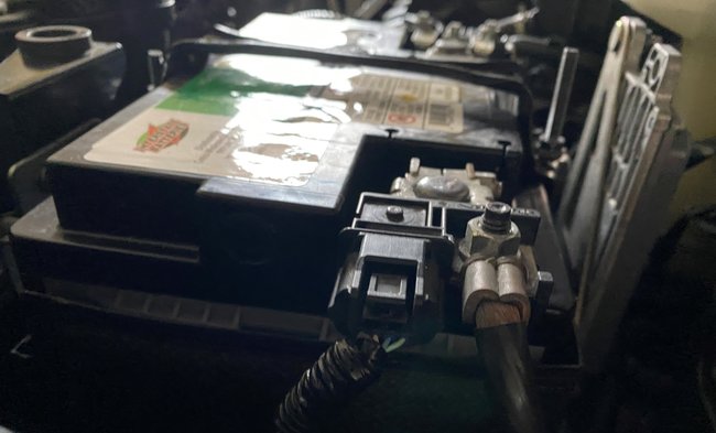
2. So I replaced 5 years old OEM Battery yesterday with an H5(47) AGM battery
3. Battery icon appears still
4. Voltmeter showed with engine off, 12.6 V on new battery
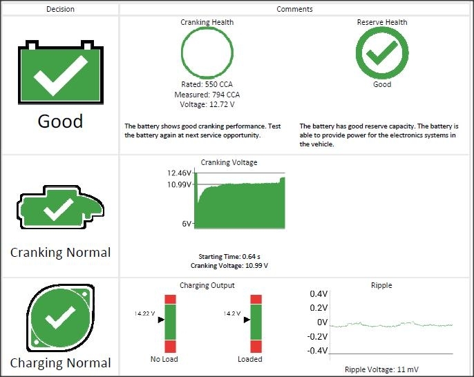
5. Drove just about 30 minutes local stop and go, few miles driven, and battery tested perfect! that is showed CCA more than Spec, all Voltage, Alternator charging and ripple voltage, starter test etc., for a normal healthy battery
6. Besides normal suspects alternator, belt, voltage regulator what could trigger battery warning?
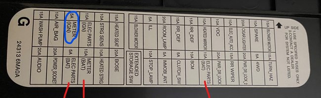
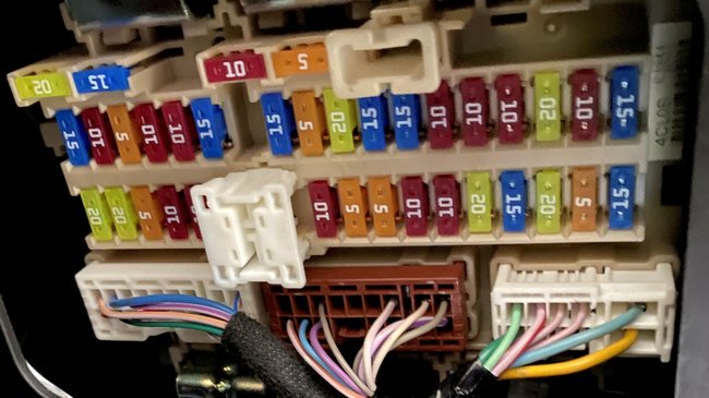
7. Are there fuses for alternator/Battery? And if fuse is out, why would it even run?
8. I am educating on +ve terminal fuses/fuse link but don't know much so if you can help, I will appreciate it.
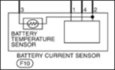
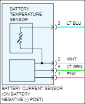
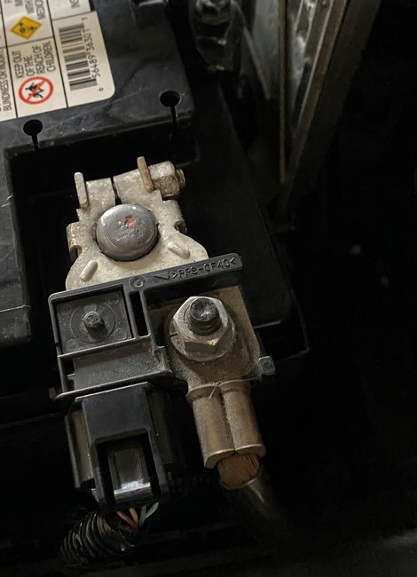
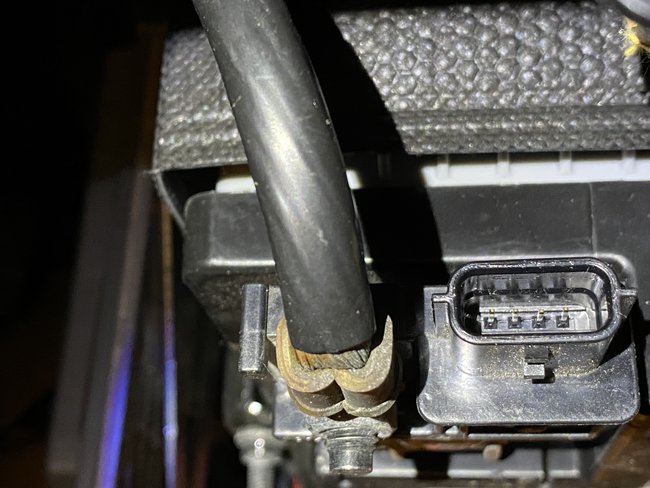
9. Could it be the current sensor on -ve terminal? or ECM?
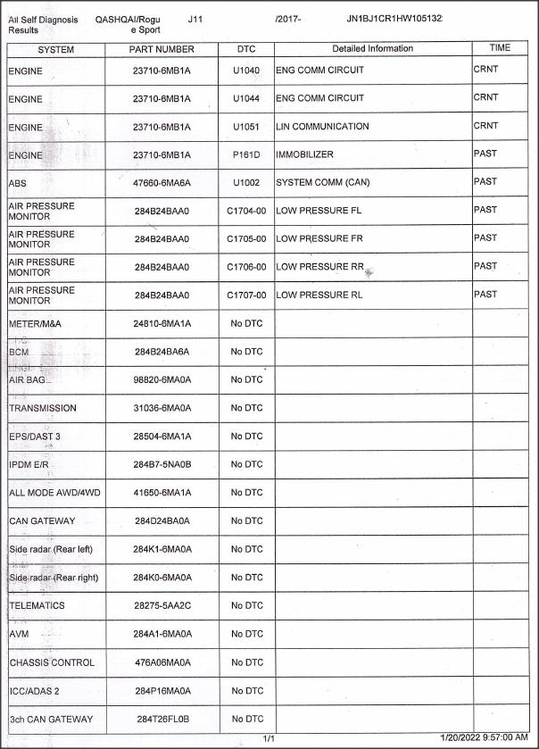
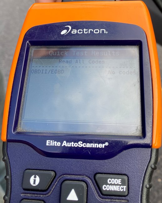
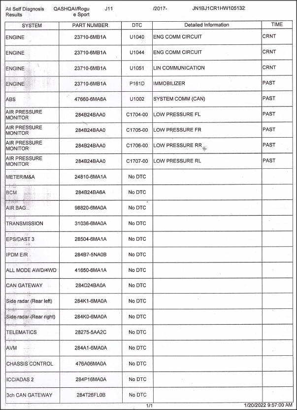
10. for fuses it refers to manual and manual does not have diagrams so got it from other fuse related sites (fuseandrelay dot com or fusecheck dot com) and no OBDII codes
Thanks for your help.
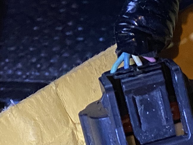
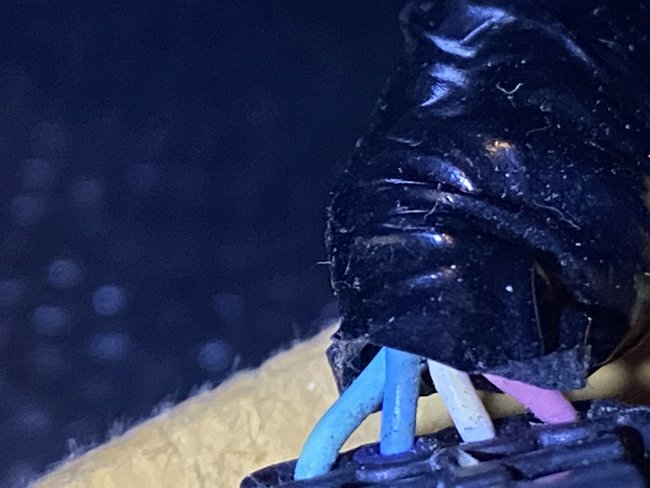
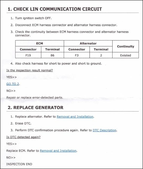
ECM Harness and Alternator Harness shows continuity. Therefore, I assume, the fusible links are not out. No shorts either.
Also, wouldn't fusible link out stop the car's engine from running?
1. Battery, starter and alternator tests passed three times, but with lower CCA on battery
2. So I replaced 5 years old OEM Battery yesterday with an H5(47) AGM battery
3. Battery icon appears still
4. Voltmeter showed with engine off, 12.6 V on new battery
5. Drove just about 30 minutes local stop and go, few miles driven, and battery tested perfect! that is showed CCA more than Spec, all Voltage, Alternator charging and ripple voltage, starter test etc., for a normal healthy battery
6. Besides normal suspects alternator, belt, voltage regulator what could trigger battery warning?
7. Are there fuses for alternator/Battery? And if fuse is out, why would it even run?
8. I am educating on +ve terminal fuses/fuse link but don't know much so if you can help, I will appreciate it.
9. Could it be the current sensor on -ve terminal? or ECM?
10. for fuses it refers to manual and manual does not have diagrams so got it from other fuse related sites (fuseandrelay dot com or fusecheck dot com) and no OBDII codes
Thanks for your help.
ECM Harness and Alternator Harness shows continuity. Therefore, I assume, the fusible links are not out. No shorts either.
Also, wouldn't fusible link out stop the car's engine from running?
Jan 20, 2022 at 2:40 PM