Good morning,
Go to the alternator and test for 2 wires that should have power with the key on.
https://www.2carpros.com/articles/how-to-check-wiring
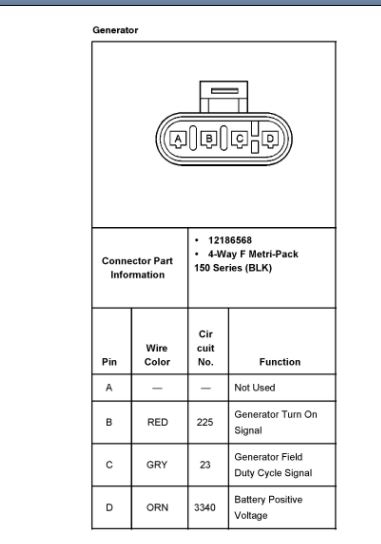
One is directly from the battery and the other is fuse controlled. I attached a picture of the connector as well.
If you have the power, then there is a good chance the ECM is the issue as it controls turning the alternator on and off to maintain the battery.
Roy
GENERATOR
The Denso generator is electrically similar to earlier models. The generator features the following major components:
- The delta stator
- The rectifier bridge
- The rotor with slip rings and brushes
- A conventional pulley
- Dual internal fans
- The regulator
The pulley and the fan cool the slip ring and the frame.
The generator features permanently lubricated bearings. Service should only include tightening of mount components. Otherwise, replace the generator as a complete unit.
REGULATOR
The voltage regulator controls the rotor field current in order to limit the system voltage. When the field current is on, the regulator switches the current on and off at a rate of 400 cycles per second in order to perform the following functions:
- Radio noise control
- Obtain the correct average current needed for proper system voltage control
At high speeds, the on-time may be 10 percent with the off-time at 90 percent. At low speeds, the on-time may be 90 percent and the off-time 10 percent.
CIRCUIT DESCRIPTION
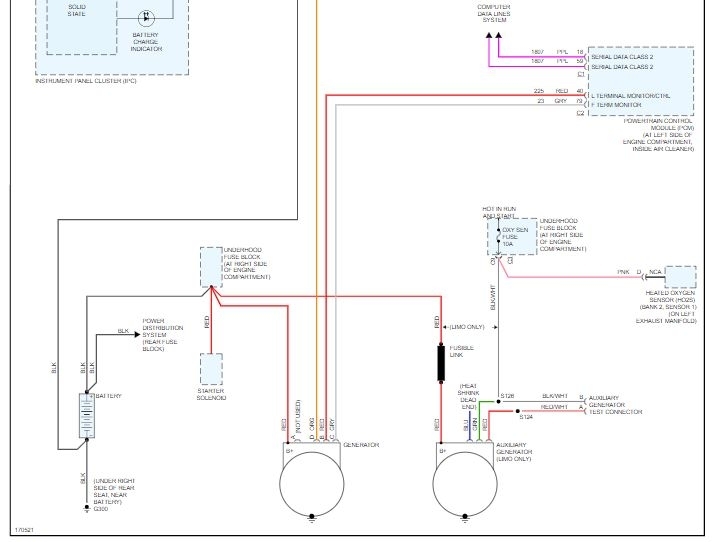
The generator provides voltage to operate the vehicle's electrical system and to charge its battery. A magnetic field is created when current flows through the rotor. This field rotates as the rotor is driven by the engine, creating an AC voltage in the stator windings. The AC voltage is converted to DC by the rectifier bridge and is supplied to the electrical system at the battery terminal.
When the engine is running, the generator turn-on signal is sent to the generator from the PCM, turning on the regulator. The generator's voltage regulator controls current to the rotor, thereby controlling the output voltage. The rotor current is proportional to the electrical pulse width supplied by the regulator.
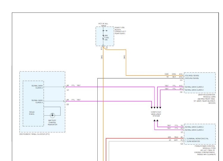
When the engine is started, the regulator senses generator rotation by detecting AC voltage at the stator through an internal wire. Once the engine is running, the regulator varies the field current by controlling the pulse width. This regulates the generator output voltage for proper battery charging and electrical system operation. The generator F terminal is connected internally to the voltage regulator and externally to the PCM. When the voltage regulator detects a charging system problem, it grounds this circuit to signal the PCM that a problem exists. The PCM monitors the generator field duty cycle signal circuit. The system voltage sense circuit receives battery positive voltage that is Hot At All Times through the DIM fuse in the rear fuse block. This voltage is used by the regulator as the reference for system voltage control.
LIMO (WC5)
This is a dual generator system, with a primary and secondary generator. The primary generator is the standard equipment generator. and operates as described in the above text.
The secondary generator is a smaller generator. Refer to Generator Usage. This generator is used to maintain battery voltage over an extended idle period with high loads. This generator functions the same as other generators, but is not PCM controlled.
When the engine is running power is sent to the battery positive voltage sense circuit, turning on the regulator. The regulator uses the input voltage to control the output of the generator.
The battery positive voltage output circuit of this generator is connected to the battery positive voltage terminal on the underhood bussed electrical center.
The wiring harness for this generator also contains a test terminal for the lamp circuit of the generator.
CHARGING SYSTEM INDICATORS
The IPC illuminates the charge indicator when the following occurs:
- The PCM detects that the generator output is less than 11 volts or greater than 16 volts. The IPC receives a class 2 message from the PCM requesting illumination.
- The IPC determines that the system voltage is less than 11 volts or greater than 16 volts. The IPC receives a class 2 message from the dash integration module (DIM) indicating the system voltage.
- The IPC performs the displays test at the start of each ignition cycle. The indicator illuminates for approximately 3 seconds.
BATTERY NOT CHARGING - 7
The IPC illuminates the BATTERY NOT CHARGING - 7 indicator in the DIC when the PCM detects a malfunction with the generator output. The IPC receives a class 2 message from the PCM requesting illumination.
BATTERY SAVER ACTIVE - 27
The IPC illuminates the BATTERY SAVER ACTIVE - 27 indicator in the DIC when the dash integration module (DIM) reduces or disables the performance of some vehicle systems in order to reduce the load on the charging system. The IPC receives a class 2 message from the DIM requesting illumination.
BATTERY VOLTAGE HIGH - 8
The IPC illuminates the BATTERY VOLTAGE HIGH - 8 indicator in the DIC when the IPC determines that the system voltage is greater than 16 volts. The IPC receives a class 2 message from the dash integration module (DIM) indicating the system voltage.
BATTERY VOLTAGE LOW - 6
The IPC illuminates the BATTERY VOLTAGE LOW - 6 indicator in the DIC when the IPC determines that the system voltage is less than 11 volts. The IPC receives a class 2 message from the dash integration module (DIM) indicating the system voltage.
SERVICE CHARGING SYS - 102
The IPC illuminates the SERVICE CHARGING SYS - 102 indicator in the DIC when the PCM detects a malfunction with the generator output. The IPC receives a class 2 message from the PCM requesting illumination.
REMOVAL PROCEDURE
The Denso SC1 (KG9) generator is serviced as a complete unit only.
1. Disconnect the battery negative cable.
2. Remove the drive belt
3. Remove the radiator.
imageOpen In New TabZoom/Print
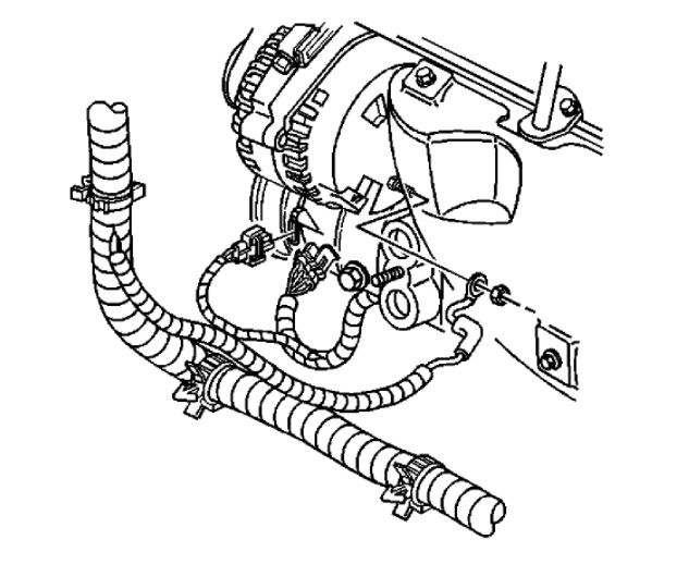
4. Disconnect the wiring harness connector from the generator.
5. Reposition the protective boot from the generator output BAT terminal for access.
6. Remove the generator output BAT terminal nut and disconnect the positive lead from the generator.
imageOpen In New TabZoom/Print
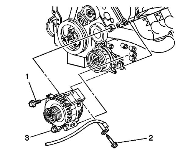
7. Loosen the lower generator bolt (3).
8. Remove the generator bolts (1, 2) from the generator.
9. Remove the generator from the vehicle.
GENERATOR
The Denso generator is electrically similar to earlier models. The generator features the following major components:
- The delta stator
- The rectifier bridge
- The rotor with slip rings and brushes
- A conventional pulley
- Dual internal fans
- The regulator
The pulley and the fan cool the slip ring and the frame.
The generator features permanently lubricated bearings. Service should only include tightening of mount components. Otherwise, replace the generator as a complete unit.
REGULATOR
The voltage regulator controls the rotor field current in order to limit the system voltage. When the field current is on, the regulator switches the current on and off at a rate of 400 cycles per second in order to perform the following functions:
- Radio noise control
- Obtain the correct average current needed for proper system voltage control
At high speeds, the on-time may be 10 percent with the off-time at 90 percent. At low speeds, the on-time may be 90 percent and the off-time 10 percent.
CIRCUIT DESCRIPTION
The generator provides voltage to operate the vehicle's electrical system and to charge its battery. A magnetic field is created when current flows through the rotor. This field rotates as the rotor is driven by the engine, creating an AC voltage in the stator windings. The AC voltage is converted to DC by the rectifier bridge and is supplied to the electrical system at the battery terminal.
When the engine is running, the generator turn-on signal is sent to the generator from the PCM, turning on the regulator. The generator's voltage regulator controls current to the rotor, thereby controlling the output voltage. The rotor current is proportional to the electrical pulse width supplied by the regulator.
When the engine is started, the regulator senses generator rotation by detecting AC voltage at the stator through an internal wire. Once the engine is running, the regulator varies the field current by controlling the pulse width. This regulates the generator output voltage for proper battery charging and electrical system operation. The generator F terminal is connected internally to the voltage regulator and externally to the PCM. When the voltage regulator detects a charging system problem, it grounds this circuit to signal the PCM that a problem exists. The PCM monitors the generator field duty cycle signal circuit. The system voltage sense circuit receives battery positive voltage that is Hot At All Times through the DIM fuse in the rear fuse block. This voltage is used by the regulator as the reference for system voltage control.
LIMO (WC5)
This is a dual generator system, with a primary and secondary generator. The primary generator is the standard equipment generator. and operates as described in the above text.
The secondary generator is a smaller generator. Refer to Generator Usage. This generator is used to maintain battery voltage over an extended idle period with high loads. This generator functions the same as other generators, but is not PCM controlled.
When the engine is running power is sent to the battery positive voltage sense circuit, turning on the regulator. The regulator uses the input voltage to control the output of the generator.
The battery positive voltage output circuit of this generator is connected to the battery positive voltage terminal on the underhood bussed electrical center.
The wiring harness for this generator also contains a test terminal for the lamp circuit of the generator.
CHARGING SYSTEM INDICATORS
The IPC illuminates the charge indicator when the following occurs:
- The PCM detects that the generator output is less than 11 volts or greater than 16 volts. The IPC receives a class 2 message from the PCM requesting illumination.
- The IPC determines that the system voltage is less than 11 volts or greater than 16 volts. The IPC receives a class 2 message from the dash integration module (DIM) indicating the system voltage.
- The IPC performs the displays test at the start of each ignition cycle. The indicator illuminates for approximately 3 seconds.
BATTERY NOT CHARGING - 7
The IPC illuminates the BATTERY NOT CHARGING - 7 indicator in the DIC when the PCM detects a malfunction with the generator output. The IPC receives a class 2 message from the PCM requesting illumination.
BATTERY SAVER ACTIVE - 27
The IPC illuminates the BATTERY SAVER ACTIVE - 27 indicator in the DIC when the dash integration module (DIM) reduces or disables the performance of some vehicle systems in order to reduce the load on the charging system. The IPC receives a class 2 message from the DIM requesting illumination.
BATTERY VOLTAGE HIGH - 8
The IPC illuminates the BATTERY VOLTAGE HIGH - 8 indicator in the DIC when the IPC determines that the system voltage is greater than 16 volts. The IPC receives a class 2 message from the dash integration module (DIM) indicating the system voltage.
BATTERY VOLTAGE LOW - 6
The IPC illuminates the BATTERY VOLTAGE LOW - 6 indicator in the DIC when the IPC determines that the system voltage is less than 11 volts. The IPC receives a class 2 message from the dash integration module (DIM) indicating the system voltage.
SERVICE CHARGING SYS - 102
The IPC illuminates the SERVICE CHARGING SYS - 102 indicator in the DIC when the PCM detects a malfunction with the generator output. The IPC receives a class 2 message from the PCM requesting illumination.
Images (Click to make bigger)
Thursday, January 28th, 2021 AT 7:22 AM