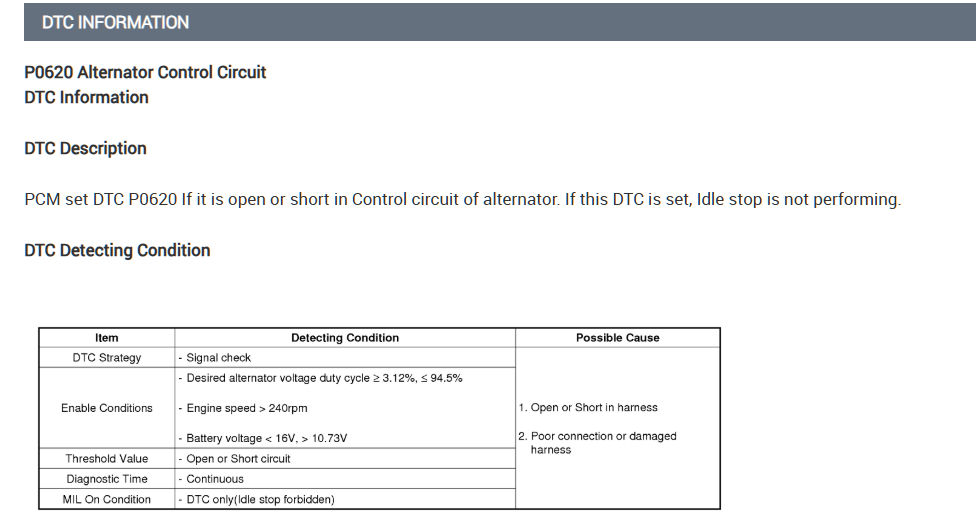
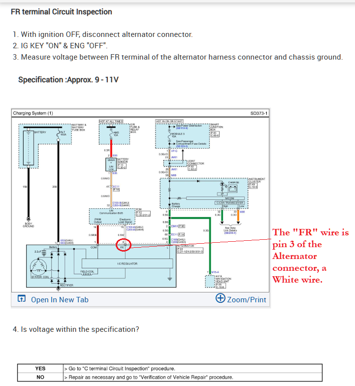
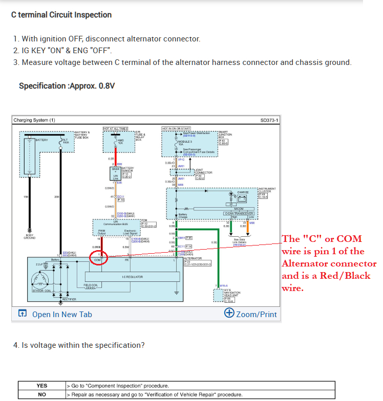
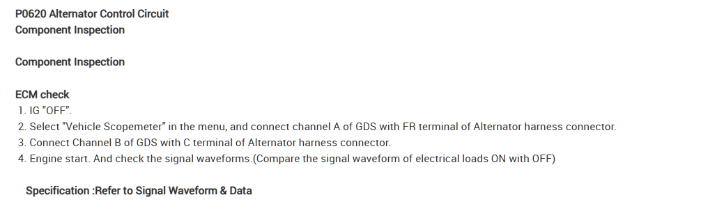
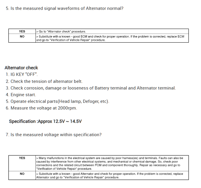
This is the code setting criteria and the testing method for this code. Service info from Hyundai first gives some testing that can be done with a multimeter (diagrams 2,3,4). With the Alternator unplugged and key On, it shows the FR wire should read 9-11volts, and on the "C" COM wire should read roughly 0.8volts (800mv).
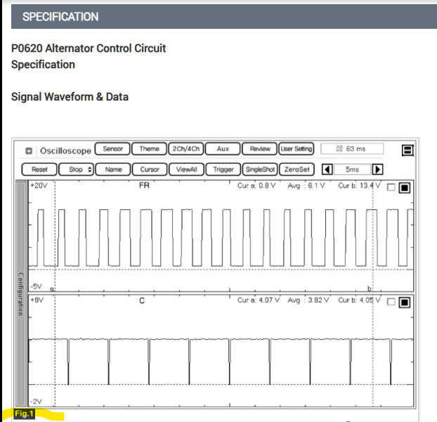
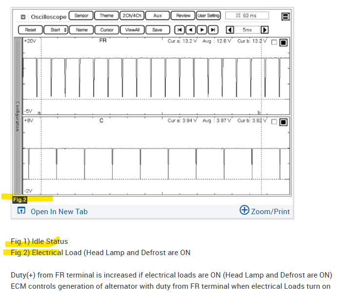
Diagrams 6,7,8 are for testing the actual signal on both of those wires, where at idle the On Time of the FR wire varies but is around 50% duty cycle, meaning its on 50% of the time and off the other 50%. The 2nd waveform shows more electrical load on the charging system, so the FR wire has a much higher duty cycle where it looks to be around 90-95% On time.
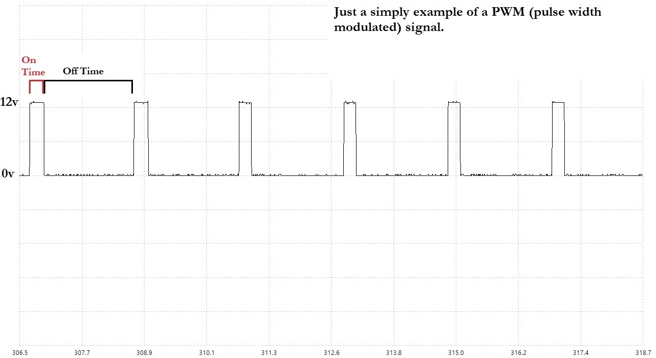
The last diagram is just a simple PWM signal for example.
The PCM regulates the FR (pin 3) wire according to the electrical load of the vehicle, Most likely what is happening is the PCM is not seeing any voltage on one of these wires. And is therefore setting the P0620 code. It can be a broken wire (open circuit) or shorted to ground on either wire.
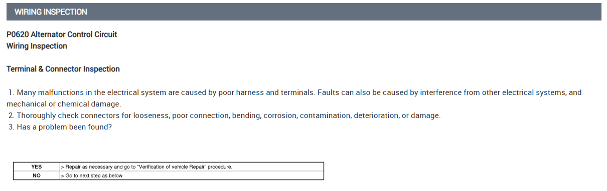
You can check the plug on the alternator for any damage, or signs of overheating which would discolor the connector and possibly melt part of it.
I would also check the fuses in the wiring diagram to see if any of them are blown, which can happen if any wires are shorted to ground. If a fuse is blown due to a short to ground, that will have to be tracked down.
Hyundai is pretty good about providing what a Known Good waveform should look like for newer vehicles.
But you can start with the multimeter testing if you are comfortable with that. Scope use gets to be much more technical. Let us know what you find.
https://www.2carpros.com/articles/how-to-use-a-voltmeter
https://www.2carpros.com/articles/how-to-check-a-car-fuse
Images (Click to enlarge)
Sep 14, 2025 at 10:23 AM