Alternator not charging battery or compensating for accessories

Tiny
MICHAEL EMULATE KAI
  • MEMBER
  • 1996 DODGE DAKOTA
  • 3.9L
  • V6
  • 2WD
  • AUTOMATIC
  • 217,000 MILES
I purchased this truck recently with this being the only issue.
It is a SLT model.

Previous owner mistakenly put the battery in backwards. It stopped charging after that and he replaced alternator, and starter motor. It won't hold the charge of the battery. It's barely pushing 11 v at the back of the little black regulator.


It's a new alternator that's been tested, the batteries are holding a charge from my wall charger. I've read a few things about PCM and tests but I'm pretty lost on what's going on.

The GEN light is on and has been the whole time. If I don't use any of the lights or anything it'll run fine and slowly drain. Please advise. Got a steal on it other than this issue, which I know has to be fixable.
Wednesday, December 30th, 2020 AT 2:08 PM

21 Replies

Tiny
CARADIODOC
  • MECHANIC
  • 33,727 POSTS
What you're describing as the "little black regulator" is in fact just a plastic terminal block with wires running through it. The voltage regulator is inside the Engine Computer. Chrysler's older firewall mounted regulators had temperature compensation built in. By putting it inside the computer, it can adjust for many other variables.

The diagnosis can be started by measuring the three voltages on the back of the alternator, but that has to be done with the engine running. You must find full battery voltage on the large wire bolted to the output stud. If that's missing, we'll have to check the fuse link wire. That comes off a stud on the power distribution center, (under-hood fuse box). My green arrow is pointing to it.

On the two smaller nuts by that black block, one must have full battery voltage, and the other one should have less, but not 0 volts.

Let me know what you find.
Was this
answer
helpful?
Yes
No
Wednesday, December 30th, 2020 AT 3:58 PM
Tiny
MICHAEL EMULATE KAI
  • MEMBER
  • 23 POSTS
The small terminal closest to the A/C compressor was the 12.2.
The next small one was like a half volt.

My multimeter has stopped working, but I was reading those two earlier before it broke.

If that helps I'm looking at getting another one here tomorrow.
Was this
answer
helpful?
Yes
No
Wednesday, December 30th, 2020 AT 4:20 PM
Tiny
MICHAEL EMULATE KAI
  • MEMBER
  • 23 POSTS
The voltage of the alternator at the small terminal.
Was this
answer
helpful?
Yes
No
Wednesday, December 30th, 2020 AT 4:21 PM
Tiny
CARADIODOC
  • MECHANIC
  • 33,727 POSTS
We'll call half a volt "0" volts. There's only two ways that voltage can be that low. The K20 18 dark green wire is shorted to ground, or the brushes are worn inside the alternator. Even a shorted voltage regulator can't bring that voltage all the way down to 0 volts due to all the additional circuitry inside the computer. When the regulator wants the system to charge wide-open, it will only pull that circuit down to about 4 volts. The lower that voltage is, the bigger the difference is between them, and the bigger the electromagnetic field it builds, which creates more output.

If the dark green wire was shorted to ground, the system would be full-fielded and charging wide open. You have the opposite problem. I've run into this three times over the years on my older Caravans and Voyagers. In two of them I was able to replace the brush assemblies without removing the alternators from the engine. The last one had badly torn up Philips-head bolts, so I had to do the repairs with the alternator on the bench.

You're going to have the little silver Nippendenso alternator. Once you remove the three nuts, and then the wires, there's two or three larger nuts that hold the stamped rear cover on. Pry that cover off, then the brush assembly will be visible. In this photo, the red arrow is pointing to what worn brushes look like. The blue arrow is pointing to the new ones. This assembly costs around ten dollars. I don't know if you can buy them at auto parts stores. I get mine from a local starter / generator rebuilder company. Most larger cities have at least one. If you can't find any, ask at any heavy truck repair shop or heavy equipment dealer. They send starters there all the time to be rebuilt.

When you take the two small nuts off, they are often rusted tight and the small studs might twist off. The two orange arrows are pointing to them. That entire block can be unbolted, then use a small punch to drive the broken bolt out, and pop in a new one of similar size. You can also harvest that part at a pick-your-own-parts salvage yard.

Normally that block stays on the alternator. If you look at the new assembly, you'll see three metal tabs with holes in them. The three corresponding screws are all that have to be removed. One of them is shown removed on the old assembly at the top of the photo.

You'll have to hold the spring-loaded brushes retracted to slide them over the slip rings. Other manufacturers have a small hole to stick a toothpick or paper clip through to hold them out of the way until they're installed. You don't need that with this alternator.

Of course you could just replace the entire alternator. Before you approach this either way, do a continuity test between the two small terminals. You should find 4 ohms, plus whatever resistance is in your meter's leads. Be aware it is real common, even with brand new brushes, for a little debris to get under them and hold them up from making good contact with the slip rings. That will not be an issue once the field winding is spinning. If you come up with an open circuit, just irritate the belt a little. The slight movement of the pulley will usually make a good enough connection to verify the brushes are okay.
Was this
answer
helpful?
Yes
No
Wednesday, December 30th, 2020 AT 4:56 PM
Tiny
MICHAEL EMULATE KAI
  • MEMBER
  • 23 POSTS
Okay, got a digital meter here are readings.

Small terminal driver side : 11.43.

Small terminal middle : 0.45 - 0.50.

Large cable : 46- 47 V (had to use 200 not 20v to measure).

That help diagnosis?
Was this
answer
helpful?
Yes
No
Wednesday, December 30th, 2020 AT 4:59 PM
Tiny
MICHAEL EMULATE KAI
  • MEMBER
  • 23 POSTS
It is a brand new alternator. Had it tested yesterday and it passed completely. The previous owner had tried to solve the issue a few ways. I can swap it at AutoZone for a new one and see if that solves the issue?

I did an OBDII test for codes and it's all clear.

I believe you could be right just want to get all the information I can before I break open a shiny alternator.
Was this
answer
helpful?
Yes
No
Wednesday, December 30th, 2020 AT 5:17 PM
Tiny
CARADIODOC
  • MECHANIC
  • 33,727 POSTS
You can't have 47 volts in a 12-volt system. Are you using an auto-ranging digital voltmeter? I've used a friend's a few times, and have always made mistakes by overlooking the range the meter selected for me, especially when the "mv" is so tiny you can barely see it. If you're actually getting.47 volts on the output stud, the fuse link is burned open. That would be due to the previous owner connecting the battery backward. There's six diodes inside the alternator. Those are one-way valves for electrical current flow, and they're in there backward, which is what prevents the alternator's stator windings from being a dead short to ground. When the battery is reversed, that puts the diodes in there in the "forward-biased" direction, and they act like a piece of wire. That will burn open the fuse link wire.

With the fuse link burned open, you'll find 0 volts on the alternator's output stud with the engine off. At the same time, since you have a new / good alternator, the voltage regulator is going to be doing everything it can to get system voltage up to 13.75 to 14.75 volts with the engine running, but it's not going to see success. Now you'll find high voltage on the output stud, as in perhaps 16 to 18 volts. For demonstration purposes in the classroom, I've been able to get as much as 35 volts, but that's with no voltage regulator in the system, and only to prove what is possible when we use invalid troubleshooting techniques.

When you find that fuse link wire, tug gently on it to test it. If it's good, it will act like a piece of wire. If it's burned open, it will act like a rubber band. You can buy these at any auto parts store. The color of the insulation denotes its current rating, just as with regular fuses. You'll get a piece about 12" long which can be cut to make three or four repairs. The length is not important. It just needs to be smaller than the wires it protects, so it's the weak-link-in-the-chain. When you splice and solder them, seal the joints with heat-shrink tubing with hot-melt glue inside to seal out moisture. Don't use electrical tape as it will unravel into a gooey mess on a hot day.

Don't use regular wire to replace a fuse link wire. The insulation on fuse links is designed to not burn or melt. Regular wire might indeed protect the circuit, but it could also start a fire.
Was this
answer
helpful?
Yes
No
Wednesday, December 30th, 2020 AT 5:41 PM
Tiny
MICHAEL EMULATE KAI
  • MEMBER
  • 23 POSTS
Where would they be in the harness? Or should I look for a diagram? I'm not seeing any obvious fuse links. I will start up again tomorrow.
Was this
answer
helpful?
Yes
No
Wednesday, December 30th, 2020 AT 9:09 PM
Tiny
CARADIODOC
  • MECHANIC
  • 33,727 POSTS
From what I see on the diagram, there's two studs on the Power Distribution Center, (under-hood fuse box). On one off them, 12 volts comes through a black bullet connector and wire from the battery. The fuse link wire is connected to the other stud. On newer models, they use a regular fuse and sometimes two, built into the battery cable clamp, but yours is shown as a wire.
Was this
answer
helpful?
Yes
No
Wednesday, December 30th, 2020 AT 9:29 PM
Tiny
MICHAEL EMULATE KAI
  • MEMBER
  • 23 POSTS
Still a bit lost. Is the disconnected black bullet connector the one you're referring to?
Was this
answer
helpful?
Yes
No
Thursday, December 31st, 2020 AT 8:41 AM
Tiny
MICHAEL EMULATE KAI
  • MEMBER
  • 23 POSTS
Is this isolated wire the fuse link?
Was this
answer
helpful?
Yes
No
Thursday, December 31st, 2020 AT 8:43 AM
Tiny
MICHAEL EMULATE KAI
  • MEMBER
  • 23 POSTS
Located and removed. It's a 10 gauge. Fuselink. Do I need souldering or can I splice it in?
Was this
answer
helpful?
Yes
No
Thursday, December 31st, 2020 AT 9:04 AM
Tiny
CARADIODOC
  • MECHANIC
  • 33,727 POSTS
Rats. You got ahead of me. I'm going to post these photos anyway for the benefit of others who may research this topic.

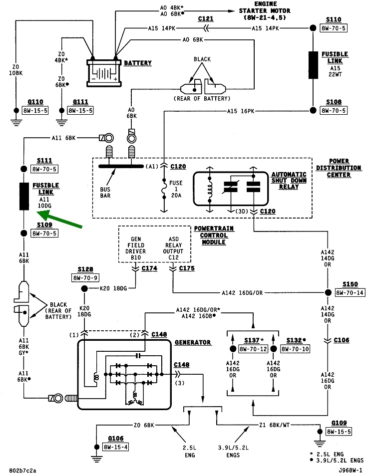
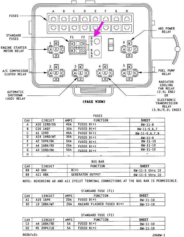
First of all, I see the reason for some confusion. The first drawing is of your Power Distribution Center, (PDC), under the hood. I had expected to see the two buss bar studs in one corner, sticking out from the box. In fact, yours are tucked away in the middle, as shown with my purple arrow. You should be able to reach down in there and measure 12 volts on both studs all the time. For your current problem, I suspect you'll find 0 volts.

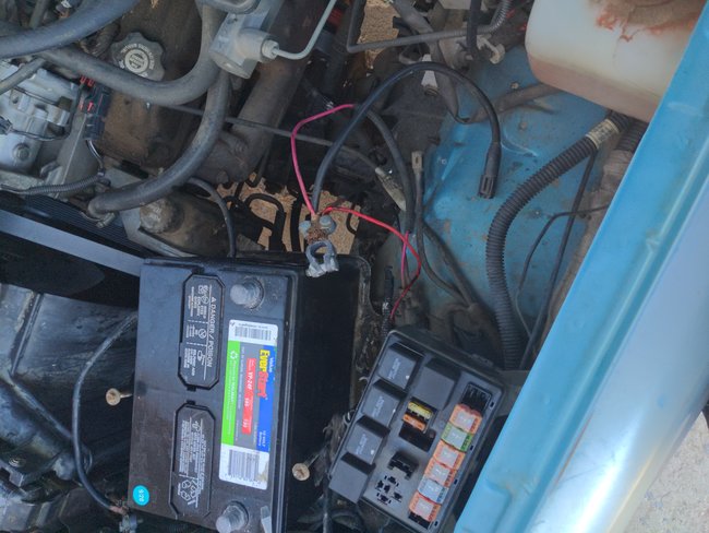
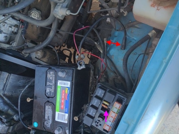
In the third photo, you did find the bullet connector. I added red arrows to it.

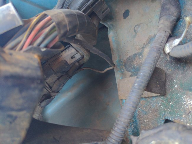
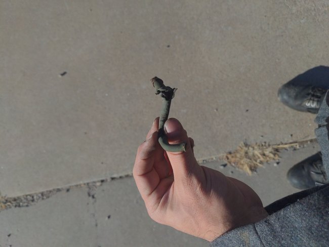
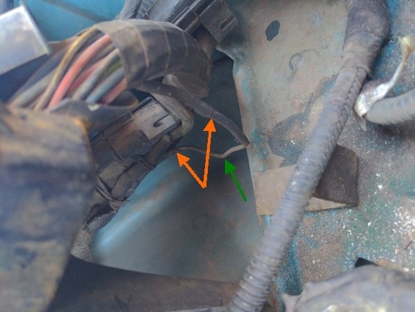
In the fourth photo, you found the fuse link wire. It's common to hide them away as you don't have to access them very often. On the older front-wheel-drive cars from the mid '80s to mid '90s, you'll find a whole bunch of fuse link wires wrapped together in a bundle going around the left front strut tower. The two orange arrows are pointing to the moisture-proof heat-shrink tubing used at the factory. The green arrow is pointing to the fuse link wire itself.

To replace the fuse link, cut the 6 gauge black wire just beyond the heat-shrink tubing on both ends of the fuse link. Strip those back about a half inch. Be sure the copper wires are clean and shiny, otherwise solder won't adhere to them. Cut a piece of the new fuse link long enough to easily connect to the two black wires, and strip those ends. When splicing the joints, it's easiest to not twist the ends together like you would with house wiring and wire nuts. That makes them too hard to seal. Instead, overlap the two ends, and twist them around each other to make a good mechanical connection first, then solder them to make a good electrical connection.

When the first joint is soldered, slide on a piece of moisture-proof heat-shrink tubing, and warm it with a lit match or hot-air gun until the glue oozes out on both ends. Don't try to use electrical tape. That will unravel into a gooey mess on a hot day.

The next step is one we often forget. Slide a second piece of heat-shrink tubing onto one of the wires where it will be far enough away from the heat of the soldering iron. Curl the two remaining wires around each other, then solder them. Before you slide the heat-shrink tubing over the joint, feel for sharp points left from an end of one of the wires sticking up. If you find any, squeeze them down with a needle-nose pliers so they don't poke through the heat-shrink tubing over time. Warm that tubing, and you're done.

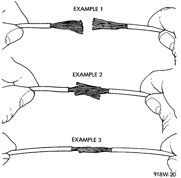
The fifth drawing shows the recommended splicing method. I prefer example 2, but that has the greater potential to leave sharp points sticking up that are easy to overlook. With larger diameter wires, some people will take a single strand a few inches long and wind it around the joint to hold it together while they solder it. The method I'm recommending is example three. It's faster and easier.
Was this
answer
helpful?
Yes
No
Thursday, December 31st, 2020 AT 2:37 PM
Tiny
MICHAEL EMULATE KAI
  • MEMBER
  • 23 POSTS
So in response, ordered a length of proper 10 gauge fuse link. Going to do a real splice job when it's delivered. To test it I had some alligator clips and a regular length of 10 g wire. Charging at 15v solved the issue very quickly. Appreciate the full explanation and as soon as the fuse link wire arrives I will do a proper solder and heat shrink job I have that just not the proper wire.

For anyone else wondering like myself. Yes, it will work with a regular wire. The fuse link is important because it's mostly fire proof insulation, unlike regular wire. So I won't be using this temporary fix more than a few days.
Chose alligator clips to make it easily removed.

Hope you don't scold me for proof of concept for myself but it was definitely just that.

Thank you again. I hope this helps anyone else who has my issue!
Was this
answer
helpful?
Yes
No
Thursday, December 31st, 2020 AT 2:55 PM
Tiny
CARADIODOC
  • MECHANIC
  • 33,727 POSTS
I'm not concerned. This was caused by the previous owner connecting the battery backward. That turns any "AC generator" into a dead short across the battery.

As a point of interest, "AC generator" is the official term today. Chrysler developed the AC generator for 1960 models and copyrighted the term, "alternator". Other manufacturers designs didn't show up until starting in 1964. Most of them don't use the term "alternator", but we all know what is meant when you ask for one.

Chrysler also had the first electronic voltage regulator in 1970. Their list of firsts is really long.
Was this
answer
helpful?
Yes
No
Thursday, December 31st, 2020 AT 4:32 PM
Tiny
MICHAEL EMULATE KAI
  • MEMBER
  • 23 POSTS
Just as a last question the 15v isn't a bad thing correct? I know typically it's pushing 14v but I don't think anything under 18v is dangerous? Again assuming the regular wire is giving a bit more flow?
Was this
answer
helpful?
Yes
No
Thursday, December 31st, 2020 AT 4:35 PM
Tiny
CARADIODOC
  • MECHANIC
  • 33,727 POSTS
That wire doesn't matter. It's smaller than the wires it protects, so it will have just slightly more resistance, and therefore more heat will be developed, but they take that into account when designing the circuit. The 15 volts you're finding is nothing to worry about. Depending on which text book you read, 13.75 to 14.75 volts is acceptable. Below 13.75 volts, the electrons won't have any incentive to be pushed into the battery's plates to be stored there. Above 14.75, we start to worry about boiling the water out of the battery acid.

Related to this, when a battery gets to be around three or four years old, you may see system voltage rise a little. As they age, the lead flakes off the plates and collects in the bottom of the case. With less lead left on the plates, the battery, in effect, becomes smaller, but charging current doesn't go down accordingly. The electrons coming in have to pile into what's left of the plates, and that generates more heat than normal. What's left of the plates become fully-charged faster, then it's normal for voltage to start to increase.

As the heat goes up, the acid bubbles more vigorously. Those bubbles can reach the underside of the top of the case and pop there, leaving liquid on the case. From there it migrates to the posts and out next to them, resulting in the white corrosion we find there.

What I found over years at the dealership was if you find corrosion around the battery's posts, it is going to fail with a shorted cell within ix months. They're usually close to the end of their typical five-year life span at that point. Cleaning off the corrosion won't solve anything. Conversely, if you don't find that corrosion, there is no need and no advantage to using chemical treatments such as the "juicy rings" we like to sell with new batteries.
Was this
answer
helpful?
Yes
No
Thursday, December 31st, 2020 AT 4:50 PM
Tiny
MICHAEL EMULATE KAI
  • MEMBER
  • 23 POSTS
Alright I'll invest in a new battery I can imagine this one is pretty old.
Was this
answer
helpful?
Yes
No
Thursday, December 31st, 2020 AT 4:53 PM
Tiny
CARADIODOC
  • MECHANIC
  • 33,727 POSTS
I didn't mean you need a new battery. I just posted that great and wondrous information to share with anyone who is interested.
Was this
answer
helpful?
Yes
No
Thursday, December 31st, 2020 AT 5:19 PM
Tiny
MICHAEL EMULATE KAI
  • MEMBER
  • 23 POSTS
Agreed, but given this was the one he drained constantly to drive the truck without a charge circuit I'd say I need a new one. Again thanks so much!
Was this
answer
helpful?
Yes
No
Thursday, December 31st, 2020 AT 5:20 PM

Please login or register to post a reply.

Sponsored links