1991 Dodge Dakota charging problem

Tiny
WASWIFTSR
  • MEMBER
  • 1991 DODGE DAKOTA
  • 119,000 MILES
Ok, after reading a lot of threads on this site and others I have yet to get a clear picture of the charging system on my 1991 dakota w/v8 tbi.
i know the voltage regulator is in the ecu.
i understand the charging control via the field coil.
i have read many times about the battery temp sensor (the one that none of the parts stores ive contacted, not even dodge lists for this vehicle). The earliest parts list refernce to a bts is on a 96.

i cannot find a connector for one on the drivers side firewall or fender. I have seen what they look like on newer models at the wrecking yard.

i have not found a bts on any wiring diagram for this year or as an input to the ecu.

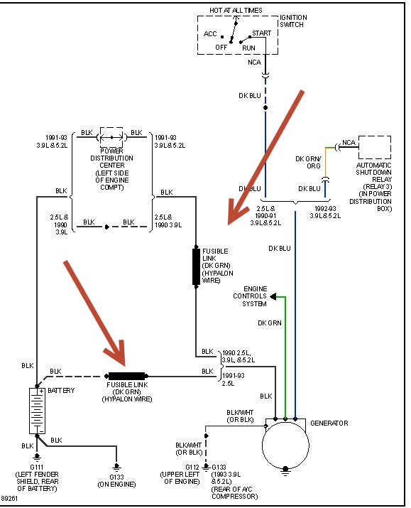
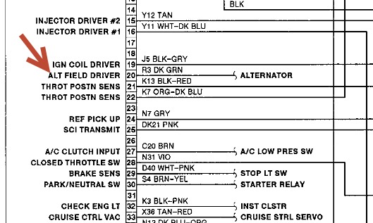
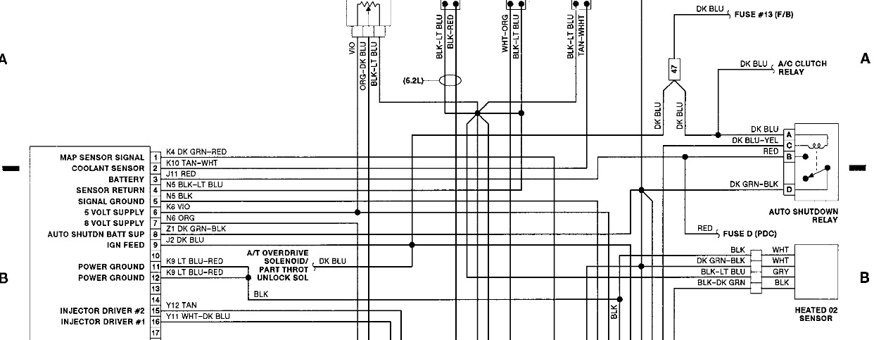
my ecu connector has a blue wire on pin 10 going to one side of the field on the alternator and a dark green going to pin 20 from the other field terminal.
this morning, for maybe 30 seconds, the input to the field was pulsing, it stopped, and did not come back even after restarting.

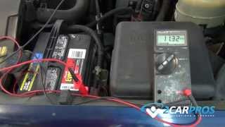
both the battery and alternator bench tested (off the truck) good.

before I spring for a new ecu, I want to be certain there is no bts on this model and the wiring is correct.

does anyone have wiring diagrams for the 1991 that actual show the bts and its inputs to the ecu?

i'm no stranger to mechanical or electrical trouble shooting, I do howerver like to have as much CORRECT information as I can get before changing costly parts.

can anyone provide correct diagrams or links to then?

Thanks
Art
Saturday, June 1st, 2013 AT 8:13 AM

10 Replies

Tiny
HMAC300
  • MECHANIC
  • 48,601 POSTS
Check the two things that are pointed to those are fusible links and they go to alternator if one or the other is burnt up your alternator won't charge cause it won't get the power it needs.
Was this
answer
helpful?
Yes
No
+6
Saturday, June 1st, 2013 AT 8:18 AM
Tiny
WASWIFTSR
  • MEMBER
  • 6 POSTS
Thanks for the quick responce.
I will recheck the conncection between the battery and the output of the alt.

If memory serves, I checked for continuity and voltage (engine not running) between the bat. + And the alt. Output terminal. Checked good.

Ill get back later
Was this
answer
helpful?
Yes
No
+2
Saturday, June 1st, 2013 AT 8:32 AM
Tiny
HMAC300
  • MECHANIC
  • 48,601 POSTS
Check those links on both sides they should have the same voltage reading ifnot then they are bad and alternator will screw up. What I sent is the correct diagram we have.
Was this
answer
helpful?
Yes
No
+1
Saturday, June 1st, 2013 AT 8:33 AM
Tiny
WASWIFTSR
  • MEMBER
  • 6 POSTS
Will check again.

Does your wiring diagram show a bts input to the ecm/u?
If this model year does not use a bts would I be correct to assume it monitor bat. Voltage and uses that to regulate charging?
Was this
answer
helpful?
Yes
No
-1
Saturday, June 1st, 2013 AT 8:40 AM
Tiny
HMAC300
  • MECHANIC
  • 48,601 POSTS
The charging system is what I showed you unless it is late year. I have no idea what a bts is and unless your automatic shutdown relay is interfering somehow and as long as you have power through the lfusible links and your battery is good it should charge. The ecu hasn't much to do with the charging anyhowif the black wire leading to the link has 12.4 volts and power is coming from ign switch on blue wire to activate the exciter then t should work.
Was this
answer
helpful?
Yes
No
+1
Saturday, June 1st, 2013 AT 11:21 AM
Tiny
WASWIFTSR
  • MEMBER
  • 6 POSTS
BTS= battery temp sensor
later dakota models (96 up)show the bts in both wiring diagrams and parts lists.
The ecm uses the battery temp as part of the charging algorithem hotter battery slower charge rate. At least one wiring diagram showed it in series with the field controlm output from the ecm.
Per your drawing, the green wire from the alternator goes to the engine controls system.

All my research indicates dodge put the voltage regulator/control (EVR) in the ecm/u, including other posts on this site.

The dark green wire and the blue wire control the field coil in the alternator.

Please check for your diagrams ecm/u conector for the alternator input, pin 10 most likely.
As I said previously, before I spring for a new ecu, I want to be certain there is no bts on this model and the wiring is correct.

Your continued assitance is greatly appricated.

Below is a discription of the EVR system from another site.
Its for a newer model but the priciples are the same.

The Electronic Voltage Regulator (EVR) is not a separate component. It is actually a voltage regulating circuit located within the PCM (Powertrain Control Module) (within the ECM for diesel engines). The EVR is not serviced separately. If replacement is necessary, the PCM must be replaced.

The amount of direct current produced by the generator is controlled by EVR circuitry contained within the PCM. This circuitry is connected in series with the generators second rotor field terminal and its ground.

Voltage is regulated by cycling the ground path to control the strength of the rotor magnetic field. The EVR circuitry monitors system line voltage (B+) and battery temperature (refer to Battery Temperature Sensor for more information). It then determines a target charging voltage. If sensed battery voltage is 0.5 volts or lower than the target voltage, the PCM grounds the field winding until sensed battery voltage is 0.5 volt above target voltage. A circuit in the PCM cycles the ground side of the generator field up to 100 times per second (100Hz), but has the capability to ground the field control wire 100% of the time (full field) to achieve the target voltage. If the charging rate cannot be monitored (limp-in), a duty cycle of 25% is used by the PCM in order to have some generator output.
Was this
answer
helpful?
Yes
No
+3
Saturday, June 1st, 2013 AT 12:12 PM
Tiny
HMAC300
  • MECHANIC
  • 48,601 POSTS
First thing you dont' have that system on your truck the regulator is in the alternator if your battery is in bad shape the alternator won't charge a bit. I have seen no replies of you checking anything that's I've sent to you. What you have is a single board engine controller that powers the field through the green wire and nothing else. I have no further suggestions to offer. You do not have the same system as a 96 so I dont' even no why you are going there. Like I said I have nothing further to offer.
Was this
answer
helpful?
Yes
No
+2
Saturday, June 1st, 2013 AT 12:26 PM
Tiny
WASWIFTSR
  • MEMBER
  • 6 POSTS
You are correct I have not yet RE-CHECKED the fusable link, your drawing indicates the second one is for a differnt model.

Please, help me understand why, if the regulator is in the alternator, there are external field terminals alternator.

I previously said the alternator and battery checked good of the truck.

Your drawing is correct, its pin not 10. What does your diagram show going in pin 10?
I have a larger gauge blue wire at pin 10 on my connector.
Was this
answer
helpful?
Yes
No
Saturday, June 1st, 2013 AT 1:05 PM
Tiny
WASWIFTSR
  • MEMBER
  • 6 POSTS
I RE-CHECKED the fusable link.
0 ohms from thr bat + to the alt. +
0 ohms bat + to bat side of the link
0 ohms relay side of the link to the relay pin
0 ohms relay pin to alt +
battery voltage 12.7vdc bat + and alt + (what it should be)

YOUR drawing indicates the second link is for a differnt model.

Please, help me understand why, if the regulator is in the alternator, there are 2 external field terminals alternator.

I previously said the alternator and battery checked good off the truck.
Regulator is in the alternator?

Your drawing is correct, its pin not 10. What does your diagram show going in pin 10?
I have a larger gauge blue wire at pin 10 on my connector.

What does my single board engine controller use as a referance (battery voltag?) To determine when to power the field through the green wire?

You have asked me to re-check items I check already and stated in my first post.
You have told me the regulator is in the alternator which is contrary to my research.
You said you never heard of a bts, even if not used on this model it is on newer ones!

My original?
Does anyone have wiring diagrams for the 1991 that actual shows the bts and its inputs to the ecu?

I aslo stated:
i'm no stranger to mechanical or electrical trouble shooting.
I do howerver like to have as much CORRECT information as I can get before changing costly parts.
Was this
answer
helpful?
Yes
No
Saturday, June 1st, 2013 AT 5:37 PM
Tiny
HMAC300
  • MECHANIC
  • 48,601 POSTS
What part don't you understand you don't have a bts in your system. There is something else going on in this system and don't pin 10 is not connected to your omputerit's pin9 which goes to ignition switch as well as auto shutdown relay. Which I think is interfering with your charging system as the same wire goes to the alternator. Like I said in many replies past. YOu keep asking abot the correct diagram which has been sent. You may have experience mechanically but you are tracking in the wrong area looking for something YOU DON"T HAVE. Disconnect eh auto shutdown relay and see what happens or replace it with a like relay. This is the last i'll answer.
Was this
answer
helpful?
Yes
No
+1
Sunday, June 2nd, 2013 AT 6:16 AM

Please login or register to post a reply.

Sponsored links