Alignment problem

Tiny
WRENCHERHEAD
  • MEMBER
  • 1996 CHEVROLET CAVALIER
  • 2.2L
  • 4 CYL
  • 2WD
  • AUTOMATIC
  • 138,000 MILES
I have replaced all four struts complete, all four hub/brg asm, R&P, outer t/rods lower c/arms complete, stab bar bushings, link kits, half shafts, rotors, drums, pads and shoes and purchased "QuickTrick" alignment kit that does caster, camber and toe because after I finished installation the frt end has a major positive camber (+1.9 / +2.0 deg). All parts are (stock direct replacements) measured and verified to match OEM components before installing and scribed knuckle to strut and strut tower position before disassembling. The only difference I noticed was the bottom hole in the struts are elongated compared to factory struts which aren't, but again I positioned new struts to scribe marks, so there shouldn't be a difference from original as far as camber change. All bolts were also torqued to specs, to include torqueing c/arms at ride height. I have also allowed suspension to settle. What is causing the camber to be so off? The only thing left to do is put camber kits in, but it shouldn't need them with stock replacements. In the 53 years I've been wrenching I've never run across this situation. For the first time I'm at a loss. Am I missing something?
Monday, June 17th, 2019 AT 10:36 PM

21 Replies

Tiny
CARADIODOC
  • MECHANIC
  • 33,752 POSTS
Those elongated lower holes are the camber adjustments. When the car is jacked up with the suspension hanging, the spindles are going to tip out as far as possible, as you have now. Once you calibrate the projectors or mirrors, and set the car down on the turntables, reach over the top of the tire with a long-handled ratchet with the appropriate extension and socket, loosen the two nuts, then nudge the wheel until camber comes down to specs. When you need to do that with the original struts, you have to remove the lower bolt, then use a die grinder to elongate the hole. GM couldn't be bothered to do that for you.

You can also buy aftermarket cam bolts to put in the lower holes. Those came standard on most Chrysler products right from the factory. The large heads help hold the strut to the spindle so camber can't slip when you hit pot holes, and they make fine-tuning the adjustment real easy by loosening the nuts, then rotating the cam bolt. Always start too low, then adjust camber up higher until you get it where you want it, then tighten the nuts. That way the head of the bolt is already holding the strut up and the weight of the car can't make the adjustment slip.

Forget about changing caster. That has half the effect on pulling as does camber, on trucks and older rear-wheel-drive cars, but it has no effect at all on front-wheel-drive cars. I've had cars with as much as 3.00 degrees difference in caster, and they went straight down the road.

Let me add one word of warning that to my knowledge, only applies to GM front-wheel-drive cars. Major engine or transmission repairs are done by lowering the cross member with the struts still attached to the spindles. You absolutely must mark the orientation of the four bolts for the cross member before they are removed, then you have to reinstall it the same way. Chrysler uses special bolts that force the cross member to line up perfectly, and on Fords, the cross members are welded in place. On GM cars, if the cross member is reinstalled off to either side, both lower ball joints will be moved to the side, and that makes both struts tip that way too. Inexperienced alignment mechanics will see the two camber readings with both wheels tipped one way, and they'll try to readjust them Usually you can get them to specs, but the ball joints are still moved and the struts are tipped at unequal angles. That angle is called "steering axis inclination", (SAI). Even though camber will look equal on the alignment computer, that unequal SAI will cause the car to be way too miserable to drive. There will be no "predictability", meaning you have no idea which direction it is going to dart with the tiniest of bumps in the road. People will think you're drunk. No spec is ever given for SAI but every alignment computer measures it while you do the caster swing. All that is important is SAI is exactly equal on both sides, plus or minus about 0.2 degrees. A typical SAI value is between 28 and 32 degrees. Most alignment mechanics never bother to look at this secondary alignment angle unless they're working with a crash repair or if they're told the cross member was removed recently. When SAI is seen to be unequal, the four bolts can be loosened right there on the alignment rack, then it can be slid with a pry bar to center it.

Don't use any anti-seize compound on the struts or lower bolts. Camber settings are maintained by the sides of the strut clamping to the spindle. Anti-seize compound makes that clamping impossible. A coworker thought he was doing me a favor by using that, then he sent the car to me to align. Three times I raised the car off the tires, pulled the spindles out, snugged the nuts, then set the car down to let gravity help sneak camber down to specs. All three times both sides slipped and the wheels tipped in as far as they could go. I thought I just hadn't tightened the nuts enough, so the third time I went overboard, and I snapped one of those bolts with a hand ratchet! You see how fat those bolts are. It pulled apart right in the middle, and I'm not that strong. There was no friction with the anti-seize compound in there. I had to wash it off both sides, find a new bolt, then start the alignment all over.

GM used strut bolts with serrations under the heads on most of their front-wheel-drive cars. Those don't work well with struts with the lower holes elongated. You have to loosen the nuts to lower the clamping forces, then nudge the wheel to specs. When you tightened the nuts, it pulled those serrations into the spindle, then they don't like to release when you loosen the nuts. You'll usually find they hold the strut tightly in place even though the nuts are real loose. You'll have to crawl underneath to tap on the thread-end to push the head out a little, then camber will slip down as far as it can go, and you have to start all over. Better to just put the four new bolts in right away. Two will have the off-center head. Those go in the bottom holes. The other two go in the top holes.

Scribing the orientation of the old struts was a good idea, but in this application, it has no value. Even if you had been reinstalling the old struts, you can end up with camber way off when that line looks perfect. The only thing that is good for is to get camber close enough for the car to driven comfortably to the alignment shop. With new struts, there is way too much tolerance in where the holes are punched, plus, there is no guarantee the flange on the new struts is the same size as on the old ones. In fact, unlike with most original GM struts, the replacements have a shoulder for the cam bolts to push on. To make room for that larger head, the flange has to be wider so the head will fit in there. Your scribe marks will be covered.
Was this
answer
helpful?
Yes
No
+1
Tuesday, June 18th, 2019 AT 1:14 AM
Tiny
WRENCHERHEAD
  • MEMBER
  • 34 POSTS
Hey there CARADIODOC. Long time since we've communicated. I must say I enjoy corresponding with you the most. You are always very thorough in your answers filled with explanation, information, and even history as to why manufacturers did or did not do certain things in their engineering process. You educate and enlighten me in the process as I always hunger for knowledge. Unfortunately most other techs don't come anywhere near your insight in providing information. You stand above them in a league of your own. From here on out my questions will be directed to you if that's alright with you. Getting to my situation on my camber problem. Here's what I left out. I put in camber kits but get this, the instructions specifically stated to install bolt in upper hole which never sat right with me, especially with the elongated hole in the bottom of strut. Even their illustrated view shows installing in the top hole. Why else would they have gone to the extent of elongating lower hole. I've always tried to rely on common sense and logic, but I assumed the manufacturer knew what they were doing, after all they're the experts (laugh). I did minimize the (+) camber but not enough to obtain factory spec of (-.2) which being the perfectionist I am didn't satisfy me. After all there's a reason why the factory comes up with their figures, it's for ideal situation to obtain maximum tire wear and handling /stability characteristics, within (+/-) tolerance range. I haven't seen on the internet specifying a different camber kit for upper or lower so I'm assuming I can use the same camber kit for the bottom. Also I'm doing the alignment myself with a QuickTrick align tool kit so I'm on the ground which (as you know) means I have to lift car and remove tire/wheel to make my adjustments, so when I set the car back down I have to settle the susp again before taking another reading. It's a pain in the rear and time consuming to say the least. But after calling several alignment shops and being told it would cost me in the range of $200-$300 with my situation, I decided to buy my own alignment kit at $289.00 and do it myself whenever needed plus other vehicles with 13-18" wheels. Now that I've used it I'm not so sure. It's labor intensive with the car on the ground, especially with the ground so rough and uneven. I look forward to your advice and suggestions. Wrencherhead (Mark)
Was this
answer
helpful?
Yes
No
Tuesday, June 18th, 2019 AT 11:08 AM
Tiny
CARADIODOC
  • MECHANIC
  • 33,752 POSTS
I just bought a used alignment computer on an auction, exactly like the one I used at the dealership. Problem is my garage is packed with house stuff after I had a house fire, so there's no room to put a hoist, and I don't have the turn tables yet. Took me an hour of moving furniture around so I could shoe-horn the computer into the garage. This model was an $18,000.00 computer when the dealer bought it for me in 1995. I got it for $300.00 at the auction.

There's a better alternative for you if you're going to do this kind of work multiple times. That is to look for an old mechanical caster / camber gauge at repair shop auctions or places like eBay. The gauge sticks to the hub magnetically, and you have to transfer it from wheel to wheel. Also, for front-wheel-drive cars, there are screw-on adapters that screw onto the stub axle / end of the outer CV joint. You might have to remove the cotter pin and stamped retainer so the adapter can butt up tightly to the axle nut. We had different adapters with different threads for different car models.

The Ammco gauge I used is shown in the photo. It's about 7" to 8" long. Another type can be seen by searching for item # 352689371546 on eBay, and there's item # 372655163514 that includes a rim clamp that will work on any vehicle.

The issue still is the tires have to be able to slide out when the suspension is settled. That requires the turn tables. When caster isn't important, you could fashion a pair of boards that sit on multiple pieces of electrical conduit, or galvanized water pipe. That would help, but it won't let the wheels turn slightly as the lower ball joint moves out but the tie rod linkage doesn't. Using my imagination, I'd try to find the large steel balls I used to save from outer CV joints or pressed-in front wheel bearings, and put a bunch of those between two thick boards. For this to work for measuring camber, the two boards have to be the same height so the front of the car is level from side-to-side. If the rear tires are on ground that's higher or lower, that would only affect the caster readings, but those don't affect pulling on front-wheel-drive cars, so it doesn't pay to try to measure it.

If you had one of the mechanical gauges, they all measure camber directly by adjusting a level so the bubble is centered, then you read the number where an arrow is pointing to the camber scale. If you wanted to measure caster, the gauges have you turn the wheel to the left, center the camber level, turn to the right, center the bubble with a different adjustment, then read caster on another scale. Basically, since caster causes a wheel to lean out on top when steered out away from the car, and it leans in when steered toward the center of the car, the amount of camber difference is proportional to the caster value. That's why two camber readings are used to calculate caster. The problem with this is the more you turn the wheel left and right, the higher the caster will appear to be. To eliminate that variable, all the gauges specify how far to turn each wheel, and you need the turn tables for that. They have a protractor scale to show how many degrees you turned that wheel. Most gauges are calibrated to be accurate when you turn the wheel out 20 degrees, set the bubble to level, then turn the wheel in 20 degrees, level the bubble, then take the reading.

After becoming accustomed to the precision of an alignment computer, I don't want to go back to mechanical gauges. Those were good enough for older rear-wheel-drive cars where a tolerance of 1/16 degree was okay, but today a lot of cars need the computer's precision that gets down to 0.01 degree.

The first thing you need to do is switch the strut bolts so the one with the eccentric head is on the bottom. It sounds like someone sold you a kit that also fits other car brands. Some imports do have the offset head on the top bolt, so if the bolts fit, revert back to your common sense and don't look at the sheet of instructions. Those bolts have to be of the same diameter as the original ones. If they're skinnier, when you rotate the cam bolt, the threaded part won't push on the spindle to move it. It also won't provide the extra security when clamping the strut to the spindle, that keeps it from shifting over time and bumpy roads.

You shouldn't have to remove a wheel to make the adjustments. We don't have enough time left in our lives to fiddle around doing that. It occurred to me that when reaching over the top of the tire, and feeling around to slide the socket onto the nuts, I needed to use a shorter extension with a swivel adapter on GM cars. The bolts are tucked inside the wheel where you can't get a straight shot at them. I have 18"-long flex-head ratchets to get enough leverage to loosen the nuts. It takes some experience to know about how much to loosen the nuts so the spindle can be pushed and pulled, but not too much that it slips down to the end of its travel due to gravity. The nice thing with old mechanical gauges is you can bang on the tire to convince the spindle to move. With the computer's projectors, you always have to worry the shock will cause the wheel adapter to shift. Those have four fingers that clamp to the outer edge of the wheel, and they slide under the tire's bead. I've had those shift without noticing, then I have to raise the car up, recalibrate the projector, set the car down, then start all over.

When you install the bolts, it doesn't matter if you put the nuts to the rear or to the front. I preferred putting them to the rear only because I felt more comfortable using the ratchet behind the tires.

I can't imagine why you were quoted such a high amount for the alignment. Probably my best suggestion would be to look for a nearby community college with an Automotive program, and ask if they'd like to use your car for training. We were always looking for live work from the community to give our kids real-world experience. They were always respectful, and well-supervised, and we charged ten dollars per hour for what the job was supposed to take. The problem is you'll only be able to bring the car in when they're teaching Suspension and Alignment. For me, that was once a year for eight weeks. Part of that time we were still learning, and part of each day was spent in the classroom, so it could take a few days to get the car back. We never did unrelated work, such as electrical repairs in Brakes class, because doing so could take work away from the shop owners who hired our graduates. Also, eight weeks means we have to stuff a lot of learning into a short time period. We have to stick to the subject being studied.

Thank you for the wonderful comments. Suspension and Alignment, Electrical, and Brakes are my three main areas I specialized in. We have a bunch of other experts who can help with these and their own areas of expertise. When you post another problem, it goes on a list that we can all read, then when the first person replies, it kind of becomes a private conversation between the two of you, but others can add comments if they previously chose to "follow" it. We do that when we don't feel comfortable that we can see the problem through to a diagnosis, but we want to learn about it or see what the final answer is. Often we'll enlist the help of other experts and get them involved when we know they can help. The goal is to solve the problem, but it can just as important to understand how the system works and what caused the problem in the first place.

Keep me updated on your progress.
Was this
answer
helpful?
Yes
No
+1
Tuesday, June 18th, 2019 AT 5:56 PM
Tiny
WRENCHERHEAD
  • MEMBER
  • 34 POSTS
I didn't get a chance to read your message until late last night and was too tired to write back till this morning. I live with and caretaker for both parents 24/7 who are 90 and 94, to include housekeeping, prepare meals, grocery shopping, doctor visits, so depending on the days schedule I have little to no time for myself to do what I need to do. Anyhow, I wish I knew then what I know now. When I read that you got the alignment computer for $300.00 my mouth hit the floor. I could have spent my money for that instead of this Mikey-Mouse kit that gets me in the ball park but not accurate enough for the $289.00 I spent. But I don't have a garage to house the computer in. I'm doing this work in a carport with that 35 year old with what used to be asphalt. It's mostly loose gravel and dirt with patch work from underground water leaks with every square inch of surface uneven with a 1 to 2 degree, grade change running downhill perpendicular to parking the car. To say the least, I don't have the ideal conditions. So I'm always fighting an uphill battle. If you get a chance when you are on the internet, take a look at my kit and let me know your opinion. It's from "Quicktrickalignment. Com" called "4th Gen". The more that I use it, the more I feel I've wasted my money. Back to my situation. The camber kit I have is Moog K90474 which has the eccentric/cam on the threaded shaft which is smaller dia than original bolts. I have to stop here. I have to attend to parents. I will continue as soon as I can. I only have one more day left on ten day permit to get it smogged for my tags. This is the fourth time for my permit and only get six per year. I'm up against the wall.
Was this
answer
helpful?
Yes
No
Thursday, June 20th, 2019 AT 10:28 AM
Tiny
WRENCHERHEAD
  • MEMBER
  • 34 POSTS
To continue about the camber kit. Again my common sense kept saying to me, how is this smaller dia bolt going to be able to secure the strut to the knuckle with all that free play on the nut side, but I tried it in the bottom hole and it wouldn't work at all. This type bolt set-up has a round washer up against the head with an angled tab/ear that interferes with the strut flange or the raised hump that is the bolt stop, which is where I needed to set the tab, so being stubborn and curious I moved the tab in between so it would flush just to test it to see if would move the knuckle any and it did nothing when I rotated the bolt, so I put back in the top hole where it did move the knuckle and torqued everything down again so I could set the car back down temporarily until I got the chance to get in touch with you. I did however manage to get the alignment into spec range temporarily so hopefully I can at least drive the car gingerly to get it smogged and get that monkey off my back. But before I drive it I wanted to get your opinion if this will be safe or not. Here are my settings as of now: camber LH FRT (+.3deg) RH FRT (-.3deg) factory spec (-.2 +/- 1deg) TOE OUT (68" FRT; 68.3/16" RR) 3/16" overall. So roughly 3/32" adj. Maybe a little less to keep within factory spec (-.1 +/-.2). By the way, is the toe spec in inches or mm? The supposed tech at Quicktrick didn't specify but after further research and printed an article "The what and why of wheel alignment states that wheel specs are normally given in angular values degrees and minutes, but in certain circumstances toe values are given in mm, therefore rim size is imperative. I'm going to assume that is for computer alignment & not in my case. I'm also going to assume the toe spec he gave me is inches. But I've been wrong before. I also haven't been able to find a camber kit with the offset head for the cavalier. Can you help me on that one?
Was this
answer
helpful?
Yes
No
Thursday, June 20th, 2019 AT 12:16 PM
Tiny
CARADIODOC
  • MECHANIC
  • 33,752 POSTS
Well, I'm going to share more than I know. First of all, when I get my garage set up to where I can use my computer, this looks like a good place to buy turntables. I've had stainless steel plates before that were real expensive, but I don't need that for home use.

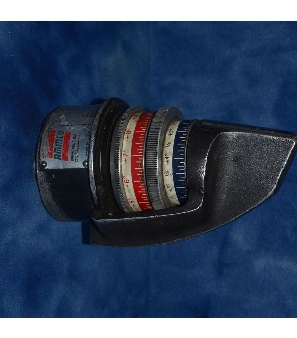
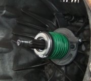
It looks like this is an upgraded version of what I used at a Sears Auto Center in the '80s. That equipment used light beams from little 12 volt car bulbs, so it could be hard to see on bright days. The biggest thing I see that concerns me is how the equipment is attached to the wheels. Some older high-end projectors used four fingers that gripped the outside of the wheel lip, and slid under the tire bead as you tightened the clamp. Others went inside the wheel lip, then the clamp was expanded to hold it there. Either way, it was always a worry that one of those fingers would slip, either from the shock when I was banging on something, or when I was pressing against it while reaching in back to put the socket on the adjuster bolt. When I thought that might have happened, I'd recalibrate that projector. That was a real pain with the first computerized aligner I used because to recalibrate one, you had to raise the vehicle on both ends and recalibrate all four projectors at the same time. The newer computer, like the one I got on the auction, lets you recalibrate just one projector at a time.

What I'm referring to is the projector sees an infrared light beam from the other projector on that side of the car, to measure toe, and it has a swinging pendulum and sensor for measuring camber. Those require the projector to be perfectly parallel to the wheel. Calibrating is done with the tire off the turntable with the car jacked up. Nothing has to be level at this point, but it has to be perfectly stable and not rocking or moving. There's a bubble level on each projector that is used only for this calibrating process. You spin the wheel by hand, then when the projector is not parallel to the wheel, the bubble will move in and out as that wheel is rotated. There's three adjustment wheels that position the projector to tweak the angle it's sitting on, and you keep doing that until the bubble never moves in and out as you spin the wheel. With experience, it takes up to a minute to do each one. When learning, it can take a few minutes for each one.

My reason for sharing this is how do you know this equipment is sitting perfectly parallel to the wheel? My procedure eliminates errors caused by a bent wheel, the fingers aren't pushed on equally, or you set a finger on a weld bead on the wheel that holds it out a little.

I couldn't tell how the measurements are taken. With the old Sears equipment, the front projector sent a light beam back to the rear wheel that had a flag, or metal screen on it. That beam also reflected back to the front projector to a screen on the back of it. The problem is that light beam's angle was affected by turning the front wheel in or out from 0.00" toe, as well as if the rear wheel was toed in or out. We had to do a lot of calculating between the readings to figure out what each wheel had. This was further aggravated by the rear wheels being closer together than the front wheels on most cars. With all these variables, this would be great for older rear-wheel-drive cars with solid rear axles, but I wouldn't trust it for the accuracy I needed for front-wheel-drive cars.

As for those specs, a lot of people set their computers up to read in degrees and minutes, as you've observed. I have to work too hard to comprehend it that way. I used to know how to convert in my head from inches of toe to degrees. As I recall, it took twice as many degrees to equal inches, as in.25" equals.50 degrees, for toe. I used degrees and hundredths of a degree for caster and camber, and hundredths of an inch for toe. All alignment computers can be set to read one or two places after the decimal point. Mechanics who set theirs to read to a tenth of a degree are after speed. Make a few adjustments until all the readings change from red to green, and that's close enough. I found that with most of the front-wheel-drive Chrysler models I was working on at the dealership, I was guaranteed no one would come back with a complaint when I set the left front wheel 0.06 degrees camber higher than the right front. The cars also went perfectly straight on my favorite test-drive route. If I had my computer set to read to tenths of a degree, 0.34 would be rounded down to 0.3 degrees, and 0.36 would be rounded up to 0.4 degrees. That looked like I had a 0.1 degrees pull to the left to make up for road crown, which is too much, when I really had 0.02 degrees, which is not enough. Luckily, unlike at Sears, my bosses and service managers never yelled at me once for taking too long on any job, so I was free to do a better alignment to keep our customers happy.

Here's what I found for specs for your car:

1996 Chevrolet Cavalier
L4-2.2L VIN 4

Front Alignment Specifications
CASTER ANGLE, DEGREES [1]
Desired. +4.3
Limits. +3.3 to +5.3

CAMBER ANGLE, DEGREES
Desired. -0.2
Limits. -1.20 to + 0.85

TOTAL TOE, DEGREES. +0.1

[1] Non-adjustable, for inspection purposes only.

Camber agrees with what you listed. Negative means the wheels are tipped in on top. Any time you see a negative camber spec, it is almost always for better cornering at the expense of tire wear. Most cars call for slightly positive camber because that tends to place the vehicle's weight directly over the center of the wheel bearing. On older cars that was to set the weight right over the larger inner wheel bearing which carried the load. The smaller outer bearing was just there to hold the wheel in position.

The acceptable range of roughly plus or minus one degree is absolutely not acceptable. At either of those extremes you'll have almost as much tire wear as you get with older Ford front-wheel-drive cars where camber was not adjustable. Tires on Escorts and Tempos lasted about 15,000 miles. The reason GM allows such a wide range of tolerance is when the car comes in under warranty with a complaint of tire wear or pulling, they will not pay for a warranty alignment if the wheels fall within that huge range. They have a lot of ways like that of getting out of paying for things other manufacturers would cover.

Your camber readings are going to cause a pretty hard pull to the left, although camber affects different car models differently. You have a 0.6 degree pull left. Remember, I used to adjust in a 0.06 degree pull to offset road crown and make the cars go straight.

For many years, GM front-wheel-drive specs were real easy to remember. "0.00" all the way around. 0.00 degrees for front and rear camber, and 0.00" of toe. There might be some confusion with your toe specs. You listed "toe-out", but the numbers show toe-in. I suspect you're using a tape measure, then the 68" is irrelevant to the story. We're interested in the difference between the readings in front and in back of the front tires. The computers go off the front and rear edges of the wheel, so the difference between a 13" or 14" wheel is negligible. When you go from the outer edges of the tires, the difference is going to be greater.

The 0.1 degree spec you listed equates to 0.05". I set all my cars to 0.06" so both wheels were the same. That's 1/16" toe in. Back in the late '70s there were a few new front-wheel-drive models that did call for a little toe-out, thinking the stress of pulling the car would pull them forward and make them perfectly parallel. That thinking has gone away. Almost all cars call for a little toe-in, then road forces pull them back while driving, to make them parallel to each other.

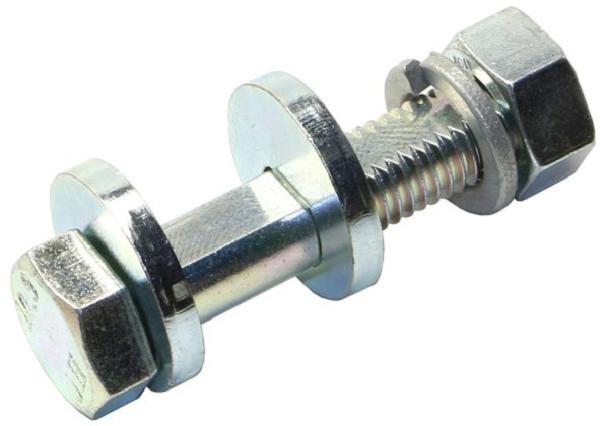
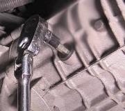
I see the problem with the cam bolts you were given. Those are for use with GM's original struts that don't have the elongated lower hole. The bolt is skinnier except for the small section in the middle. That part stays centered within the hole, then as the rest of the bolt is turned, since it's offset, it moves the head in and out. The special washer has two tabs to lock it to the strut, so the bolt head pushes and pulls on the strut to move it.

You need the bolts that look like that in this photo. You'll see your replacement struts have a shoulder for the offset washers to push on. This bolt will be the same diameter as what you removed. The flat side is only there to key the washers to it.
Was this
answer
helpful?
Yes
No
+1
Thursday, June 20th, 2019 AT 6:11 PM
Tiny
WRENCHERHEAD
  • MEMBER
  • 34 POSTS
I just spent approximately 2 to 2 and a-half hours writing an explanation of what my alignment kit consists of and how it operates and at 8:30 pm I got called by may father and had to stop so I hit reply to send and it looks like it got wiped out so I don't know if you got it. Usually I can review it after replying but it's gone. That's also how slow I type. I'm gonna try to give you a quick overview. The kit comes with 4 squared alum tubes and when assembled is an upside down "T". 2 horizontals and 2 verticals for both wheels with 6 shaped pins shaped at the tips to mount it to different type wheels and adjustable for different size wheels. 2 pins to the horizontal and 1 to the vert forming a triangular mount and has a slider slot on the vert to snug to wheel. Also has a digital torpedo gauge and bubble, calibrate and a zero out button for grade/slope and a pointer for pos/neg. And 1st used to square/level tool. Camber is read by attaching it horizontally to the vertical by a bracket. Caster read by placing gauge to horizontal following sequence of turning wheels to 20 deg and back. Gauge not used for toe. Instead 2 tape measures provided attach to slots in horiz ends from 1 wheel to the other wheel in front and behind the wheels/tires, so the reading is from the wheels, not from the tires and yes I had it backwards, it is toe-in. Front is 68" and rr is 68 & 3/16". 3/16" difference overall. Is that correct or wrong? Now, more confusion, my inaccurate Chilton paperback repair states that toe-in is neg and toe-out is pos, yet all the info I've read states just the opposite. Which is correct? I've also looked at the exact style cam kit you showed me and yet when I enter my cavalier, every source keeps showing what I already have and doesn't show the style you showed. Do you know a site I can go to that shows this type? I'm getting extremely frustrated and irritated. I've got 1 more day before my temp permit expires. To get it smogged and get my tag and get that monkey off my back but don't wanna risk damage or injury by driving it without proper cam bolts.
Was this
answer
helpful?
Yes
No
Thursday, June 20th, 2019 AT 10:20 PM
Tiny
CARADIODOC
  • MECHANIC
  • 33,752 POSTS
The kit you were given is for use with the original struts that don't have the elongated lower hole.

Okay, after 35 miles, three auto parts stores, and a dealership, I finally found the correct part when speaking with an alignment specialist at a Firestone store. It's part # 41-8245 in the Northstar catalog. They show three sizes for three different groups of GM vehicles.

Towards the end of my journey, it occurred to me you don't need any of these special bolts. They are all alignment aids, not necessities. You can use both of the original bolts, but setting the wheel to the desired setting can be a tedious trial and error affair. You have to loosen the top nut just enough to remove its clamping force. The bottom nut has to be backed off to the end of the threads, then the bolt has to be tapped out far enough to slide the serrations out past the flange on the strut. Push or pull the wheel to where you want it, then tighten the bolts. The fellow at the dealership said he uses a helper to hold the wheel in position while he crawls underneath and tightens the bolts. When I did these myself, I tightened the top bolt just enough to hold the wheel, but still loose enough that I could force it to move.

Rather than using that force, and getting frustrated at having to do it over and over, the cam bolt allows you to make the adjustment by slowly turning the bolt. The eccentric washers push the strut one way or the other, and then holds it there while you tighten the bolts.

I remembered the cam bolts were blister-packed on a piece of white cardboard. Upon doing a search for "Northstar alignment aids", I found "Specialty Products Company. That sounds familiar, but I don't know where to buy these parts locally.

You're right that toe-in is positive toe.

I think there's a two-hour limit before passwords have to be renewed due to inactivity. That might explain why your post was lost. In my case, I'm often fighting with my computer, especially the last one I had with Windows 10. I found a dandy older computer with Windows XP that works much better, but sometimes it locks up while doing something, and it always seems to be when I'm in a hurry. I did figure out that when I get the blue screen of death, then the computer restarts, it goes right back to the page I was on, and if I wait another 15 - 30 seconds, all of my previous typing comes back. It was being saved on the site. Regardless, now I always copy it just before I click, "Reply". When I type long replies, I often copy and paste it into an MS Word document a few times, in case it gets lost.
Was this
answer
helpful?
Yes
No
+1
Friday, June 21st, 2019 AT 2:53 PM
Tiny
WRENCHERHEAD
  • MEMBER
  • 34 POSTS
OMG, I didn't mean for you to personally spend your day and your gas searching for the camber bolts, I was hoping you knew a web-site that carried that style. I feel bad and guilty. No one has ever done something like that for me before. You have my sincere admiration and appreciation for your exemplary efforts in trying to help me. I don't know if you get compensation from this site, but I will be first in line to demand that you get a raise if that's possible. My hat's off to you! Can I at least pay for the gas you used? Also, sorry I couldn't respond until now, It's been hell these past few days. Even at this moment I have only a few minutes before I have to try and squeeze in some more time on the car. I did find some camber kits that have the same bolt size as the originals, although I'm concerned about them using a nylon cam that has a split in them for either R and R or to work differently once inserted. Seems to me they will wear down quickly. They're kit K5330 MOOG. I've already installed them in the top as the instructions emphasized to not put them in the bottom hole with elongated bolt holes. I'm going to have to finish this most likely tonight after 9:00 - 10:00 pm. I'm still running into some problems with aligning. I'll cover that tonight. Till then, wrencherhead.
Was this
answer
helpful?
Yes
No
Tuesday, June 25th, 2019 AT 12:44 PM
Tiny
CARADIODOC
  • MECHANIC
  • 33,752 POSTS
I was 40 miles from home attending the Midwest Energy Fair, then I sat at the local library using their wireless internet. While chasing for your part, I stopped at other stores to do some shopping for things I desperately needed but didn't know it yet, so I killed two rocks with one bird.

I never used this type of kit, but regardless of what you use, remember these are all just alignment aids. When you elongate the lower hole with a die grinder, or install new struts with the elongated hole, that hole allows you to choose where to adjust the strut to so you can fine tune the camber setting. That can all be done with the two original bolts. Knowing how much to loosen the bolts so the strut can be moved in or out without it slipping too far from gravity takes experience, a lot of frustration, and usually trial and error. These alignment aids are just designed to take out some of the frustration and trial and error. You don't have to use any of them because once you have the wheel set where you want it, it's up to the clamping forces of the bolts to hold it there. The cam bolts that I listed help hold the strut from moving or slipping when you hit pot holes. The type you have is best for setting the position without having to resort to muscle to get the strut where you want it.

Your bolt allows the spindle to be moved in and out by sliding the upper hole in or out. The elongated lower hole allows for the same adjustment by sliding the lower hole in or out. You actually have two means now of adjusting camber.
Was this
answer
helpful?
Yes
No
+1
Tuesday, June 25th, 2019 AT 6:05 PM
Tiny
WRENCHERHEAD
  • MEMBER
  • 34 POSTS
You're not kidding about the trial & error & frustration before finding the right amount of loosening or tightening the bolts to hold & still allow adjustment, so I took a break from it & burned some brain cells as to what I could use to help make the job run a little smoother. First off I made some turn plates from 4 MDF boards (2 ea. Wheel) 1/2"x12"sq. With smooth veneered surfaces, drilled & recessed center holes to accept bolts, nuts & flat washers & not protrude above surface, cinched them snug enough to hold them together & still let them turn without binding, (similar to a "Lazy Susan") then laid out center & 20 deg lines. Since the wheels were already off I snugged up the strut bolts enough to hold the knuckle in place, put the wheels back on & placed the turn plates under the wheels & set the car down & reattached the alignment tool so I could check my readings as I adjusted the camber & a pry bar between the knuckle & strut to keep it in place. All-in-all, it worked out pretty darn well & made the labor less intensive, which of course is what I was after. The boards moved with the tires when jouncing & settling the suspension easier, quicker & cooperated when adjusting. The most frustrating & tiresome was all the countless times in trying to find the right combination of tools & positions to torque down the bolts. What a chore that turned to be, but I finally got it. Hearing the torque wrench click was music to my ears. Once again, I have to stop & help my parents. I do have some questions still & hope to get back to you in a while.
Was this
answer
helpful?
Yes
No
Wednesday, June 26th, 2019 AT 4:28 PM
Tiny
CARADIODOC
  • MECHANIC
  • 33,752 POSTS
Rather than being able to turn, try using a bunch of pieces of conduit between the pieces of wood. Turning 20 degrees in and out is only for measuring caster with a computerized alignment machine. You can't change caster from what you have, and it doesn't affect pulling like it does on rear-wheel-drive cars and trucks. It's more important for the tires to be able to slide out as the suspension settles. That "at-rest" position is when the camber readings relate to the specs given.
Was this
answer
helpful?
Yes
No
+1
Thursday, June 27th, 2019 AT 4:23 PM
Tiny
WRENCHERHEAD
  • MEMBER
  • 34 POSTS
That's the main reason I made the turn plates was to help aid me in getting the tires to cooperate with me instead of resisting when wrestling to get them to settle "at-rest" & when adjusting the camber. It didn't fight me near as much. I know that caster is non-adjustable, I was just curious to see how close or far from spec. They might be. That's why I laid out the 20 deg lines. What I need to know is will having the front end 1" higher on the turn plates affect only the caster reading or will it also affect camber & toe? I don't think it affects camber/toe but I wanna be sure. Of course that thought didn't come to mind before I set & torqued everything back down & I managed to get the camber to spec (-0.2) for both sides. I'm still fine tuning the toe. That reminds me, the (supposed) tech at "Quicktrick alignment" gave me the toe spec as (-.1) & you showed me (+.1). I tend to trust your info more than his, so I set it for 1/16" per side (steering whl. Centered) toe-in as per your info. Just wanted to verify with you. I used the "string-line"Took it for a test drive yesterday afternoon
Was this
answer
helpful?
Yes
No
Saturday, June 29th, 2019 AT 1:42 PM
Tiny
WRENCHERHEAD
  • MEMBER
  • 34 POSTS
Something happened while I was still typing, the screen scrolled up then down & my message to you was no longer in the reply area, it was now placed with the prior conversations we've had as though I was done & hit reply. I must have hit a wrong key accidentally. That does happen to me sometimes, so I hope what I wrote got sent to you. So i'm gonna continue where I left off. The last thing I was stating was I used the "string-line" method to get as accurately as possible with the measurements, even used a degree wheel to center steering whl, but is extremely time consuming in getting it squared-up with the car, especially with the ground so tore up & slope perpendicular to the car port & winds for the last 3 days. Here's yesterday's settings from the wheels not tires: lt frt= 1 1/4" lt rr= 1 3/16"(.06), same for rt side. Took it for a test drive. Had a minor pull to the right from possible road crown(2 lane rd). Drove it on a 3 lane highway used center lane to try & get a flat/level drive, since it's crowned through all 3 lanes. Still pulled slightly to the right. Had approx. 2-3 deg steering wheel compensation to the left which isn't much. Should have driven on the freeway but didn't have the time at that point. This morning set-up string-line again & remeasured again with steering whl centered as before. This time it was lt frt 1 1/4" lt rr 1 3/16 same: rt frt 1 5/16 rt rr 1 1/4 different. Wouldn't that cause a lh pull instead of rh? I know that visually &/or with a deg/angle-finder on the steering whl it's next to impossible to duplicate the wheel/tires to the exact position especially after moving the car from where the car sat prior. What i'm baffled at is how the lt side stayed the same but the rt side changed. Checked all of susp & steering for looseness & everything was tight. Is it possible the rt strut/knuckle shifted even though it's torqued? That just brought a thought to mind, maybe I should take a camber reading again to see if it changed/slipped. The frustration is taking hold again, especially being so close to the end. Help
Was this
answer
helpful?
Yes
No
Saturday, June 29th, 2019 AT 3:03 PM
Tiny
CARADIODOC
  • MECHANIC
  • 33,752 POSTS
I'm not clear on where you're measuring toe, but it sounds like you have toe-out on both wheels. Toe does not cause a pull, ... However, the rolling resistance of the tires is going to pull both of them back a little more, then you'll have considerably more toe-out while in motion. The two front wheels will be steering away from the center of the car, and away from each other. The car can't follow both tires, so it's going to follow the one with the most weight on it, which is almost always the right one since road crown makes the car lean onto that tire. By following the right tire, which is steering slightly to the right, the car will seem to pull that way. Toe-out also makes a car unstable in cross winds. When the wind blows from left to right, it pushes on the car and pushes more weight onto the right tire, so the car will follow that one. The wind and the direction that wheel is steering both make the car go to the right. When you have excessive toe-in, with the wind blowing the same way, the right tire will want to steer the car to the left, offsetting that wind.

Negative toe definitely is toe-out. With caster, camber, and toe, normal settings are always positive. The only cars I can remember calling for 1/16" total toe-out were the late '70s Omni and Horizon. The thinking was the tugging forward of the tires would pull on the steering linkages and cause there to be 0.00" toe or slightly toe-in when going down the road. There also was a full-size van that called for 1/16" toe-out, but that was because with toe-out on the alignment rack and turntables, the van would actually have a little toe-in when in motion.

If you do have some toe-out on front, it will show up as a choppy tire wear pattern, mostly on both inner edges. When everything else is equal, total toe always affects both tires equally as far as wear. It doesn't matter if one or both wheels are misadjusted. The only visual symptom when any one wheel is wrong is the steering wheel will be off-center. If, for example, the right wheel is toed-out a full inch and the left wheel is at 0.00", to make the car go straight, you have to turn the steering wheel to the left so the individual toe readings are equal; in this case, -0.50" toe out.

To make toe wear easier to understand, exaggerate it to help your imagination. Suppose both wheels were toed-out a real lot, then more, ... And more, ... Until both were turned 90 degrees to the car. Now it's easy to see the "leading edge" of the tread is the inner edges. Those come down the road ahead of the outer, or "trailing edges". Now imagine standing a pencil straight up, and resting the eraser on a table top. Press down a little, then drag the eraser across the table. You'll see the leading edge folds under and makes eraser crumbs, while the trailing edge lifts up off the table, and no wear takes place on that part. That is what happens to the tires with toe-out. Unlike the one-piece eraser, the tire's tread is cut into blocks of rubber, and each block is treated like that eraser. The leading edge scrubs off, and the trailing edge is left alone, so it doesn't wear down.

To boil this down, as far as tire wear, camber always only affects the one tire. It can be off equally on both, then they'll have the same wear, but incorrect camber on one wheel doesn't affect tire wear on the other tire. Toe is the opposite. We only look at total toe, and that affects both tires on that axle equally. To tell the difference, camber wear occurs on the edge of the tread, depending on which way the wheel is leaning, and the wear pattern will be smooth, but greatly accelerated on that edge. Toe wear results in the choppy pattern on both tires, and usually more so on the inner edges when there's too much toe-out, and the outer edges when there's too much toe-in. When this toe wear is real bad, you'll be able to see it. When it's not that bad, you can identify it by running your fingertips back and forth around the tire. One way will feel fairly smooth, but the other way your fingers will catch on the high edges. This is one trick I use when performing quick visual inspections during other routine services like oil changes. I can recommend an alignment in the notes, along with a number of other things customers aren't aware of.

For all practical purposes, caster doesn't affect tire wear, but for the benefit of anyone else researching this topic who might be getting ready to take the ASE certification test, caster does affect tire wear. The rationale is the higher the caster, the more the wheel will lean into a turn. (Remember, caster can't be measured directly. It's calculated from the difference in the two camber readings when doing that 20 degree swing left and right). If you look at some older GM rear-wheel-drive cars, you'll see they have 15 to 20 degrees of camber when turned fully to the side. The ASE officials think that severe tilt will lead to excessive tire wear, I guess because they think you'll be turning sharp one way in a parking lot while going 60 mph. You can't argue that caster causes tire wear, but that is about the same as saying the river level is going to rise when I empty the water out of my thimble.

To address the numbers changing after a test-drive, welcome to my world. The biggest problem professionals have is sand or dirt getting into the turntables. Those tables are free enough to let you push the car sideways with one finger. One grain of sand can cause one of the marbles to stick, and when the table doesn't slide freely, there can be sideways pressure on the tire tread, then the normal flex in control arm bushings will result in a different camber reading. I'm in the habit of bouncing the car a few times to insure they're moving freely, then I take my final readings that will be on the printout.

Your caster readings won't be affected very much by having the front tires up on the tables. This is about the same as adding one dead body in the trunk.
Was this
answer
helpful?
Yes
No
+1
Saturday, June 29th, 2019 AT 8:45 PM
Tiny
WRENCHERHEAD
  • MEMBER
  • 34 POSTS
I don't have much time to go into detail at the moment about how I got the toe readings, so I'll give you a brief explanation on the (+.1) toe in spec you gave me. I used the "string-line" method: 4 jackstands, string-line down both sides of car off center of axles & squared up (strg whl centered), measurements from outer wheel lip distance front & rear of (front wheels not tires) to string line. 1 5/16" from frt. Whl lip to string, 1 1/4" rear lip to string. Same reading for other wheel, I/16"(.0625") toe-in per wheel for a total toe-in of 1/8"(.125"). If my math is right, that equates to.05deg per whl total toe (+.1 deg)With this method the further the distance from (front or rear) wheel lip to string indicates which direction wheels are toed & which side to adjust to eliminate/minimize pull before test drive, &/or you could count the threads of the tie rods but to me is not as accurate. Is this right? So much for a brief explanation. Now for the next problem. This was done after a test drive where it had a minor pull to right probably road crown. Drove it on a 3 lane hwy in center lane (road crown both sides of road, still slight pull with a 2-3 deg left strg whl compensation. I made the toe adjustments you see now, but I forgot to re-check camber before adjusting current toe & camber now reads (-.3 deg left si, /-.1 deg rt si.) Even though it's within GM's wide range of tolerance, should I leave the left side alone & adjust the right to (-.2 deg) spec to allow for road crown or bring them both back to (-.2 deg) Unfortunately my gauge doesn't show 100'ths only 10'ths. I also read a while ago that camber affects toe, but toe doesn't necessarily affect toe. Is that correct?
Was this
answer
helpful?
Yes
No
Monday, July 1st, 2019 AT 11:07 AM
Tiny
WRENCHERHEAD
  • MEMBER
  • 34 POSTS
I just came back on-line & saw that I made a typo at the very last question. Is it correct that camber affects toe when adjusting but toe doesn't necessarily affect camber? That's why camber is the 1st adjustment to perform so says what I read. Also, when you get a chance go to "Quicktrick alignment. Com to get a clear view of how it works. The one I have is called "Gen 4 or 4th Gen, can't recall at the moment. That will be the quickest way instead of trying to explain. It just takes me too long to type the explanation with the narrow window of time I have. It's already at 100 deg outside at noon, & supposed to hit 105 deg today. Thanks
Was this
answer
helpful?
Yes
No
Monday, July 1st, 2019 AT 12:20 PM
Tiny
WRENCHERHEAD
  • MEMBER
  • 34 POSTS
Again I found another typo when I associated the pull to toe. That's what happens when I get in such a rush when typing. If I remember correctly camber is the main cause for pull. Which ever side having more (+) will pull in that direction acting like a cone that rolls in a circle. Being that the left is (-.3 ) & the right is (-.1) would tend to pull the car to the right, or in my case since both sides are (-) with.2 difference, would the higher neg side cause the pull since it wants to roll in a clockwise direction with more force than the lessor (-) side? I hope I'm learning correctly.
Was this
answer
helpful?
Yes
No
Monday, July 1st, 2019 AT 1:22 PM
Tiny
CARADIODOC
  • MECHANIC
  • 33,752 POSTS
You're correct about camber pull. Each tire wants to pull in the direction it's leaning. The goal, besides being in specs, is to have both sides equal so they counteract each other, then a little more positive camber on the left, (or slightly more negative camber on the right), to offset road crown. You're also correct that camber is the first thing that is adjusted. On most older rear-wheel-drive cars, two adjustments usually affected caster and camber on each wheel, and they had to be jockeyed back and forth until both were good on one wheel, then we had to struggle to match them on the other wheel.

The reason toe is done last can be seen if you lay on the ground in front of the wheel and look up at the steering linkage. Start at the lower ball joint. That point is fixed, at least on your car and on most models. Now find where the movement takes place when you adjust camber. On a lot of cars, that's the upper strut mount, which is a good 15" to 18" higher than the ball joint. On your car it's the slotted hole in the bottom of the strut. That's maybe 8" above the ball joint. Now look at where the steering arm is cast onto the spindle. That is roughly half as far up from the ball joint as the slotted hole is. That means if you slide the top of the spindle / bottom of the strut in a half inch, the steering arm will move in 1/4". The spindle / steering arm moved in, but the tie rod linkage stayed the same. It needed to also become 1/4" shorter to accommodate the movement of the steering arm. In effect, the steering linkage is 1/4" too long, so it pushed the end of the steering arm out, and that turned the wheel toward the center of the car. This would equate to, ... Oh, ... Perhaps an inch of toe-in.

Thanks to positive caster, camber changes as you turn the wheel left or right, but adjusting toe even a full inch is so minimal as far as changing camber that it isn't worth mentioning. The exception would be when a lot of parts are replaced when rebuilding the entire suspension system, that nothing is close to specs when starting the alignment. Then we would "rough in" camber and toe to get them reasonably close, then we'd take the first real readings and start from there.

Be aware too that for cars that call for high positive or high negative camber, the tires will be riding on an edge. When a wheel is adjusted far enough, that stub axle is going to raise or lower a little, and that will change the height on that corner, which changes camber on the other side.

Besides good tire wear, the goal of camber is to shift where the car's weight is pressing down on the wheel bearings. On older cars with inner and outer wheel bearings we used to repack with grease, the inner bearing is the larger of the two. It is intended to hold up the weight of the car, so camber is specified where it puts the weight on that bearing. The smaller outer bearing is just there to hold the wheel straight up and down. It isn't intended to hold up vehicle weight.

Wheel bearing assemblies for front-wheel-drive cars use two rows of steel marbles, and they're both the same size, so camber isn't so critical for bearing life. Negative camber helps the car take corners better at high speeds, but the trade-off is comfort. With the wheel tipped in on top, the outer row of marbles is a little higher than the inner row, so it is holding more weight. Being an inch further out from the strut, it has more leverage when you hit a bump in the road. That makes it easier to transmit that road shock up into the car's body. Now, common sense says you aren't going to feel that difference, but when you add in all the other factors that affect comfort and ride quality, if you relax each one just a little, pretty soon you'll be selling fewer cars because the competition's rides better.

We chuckled years ago when Chrysler went to aluminum master cylinders for their brake systems, to save two pounds, but that was just part of lightening their cars by a few hundred pounds.

Older rear-wheel-drive cars almost always used the "short-arm / long-arm", (SLA) suspension system where the lower control arm sat parallel to the ground, and the upper control arm was considerably shorter, and angled down toward the upper ball joint. That system was strong and offered the best possible ride quality, but it was heavy and expensive. Road shock was transmitted through the tire, wheel, and spindle before it changed direction to go through the lower ball joint and lower control arm, then it changed direction again to go through the spring, then up into the body. Such a long indirect route absorbed most of the road shock before it got to the passengers.

With a strut suspension, the shock travels through a more direct route. The tire absorbs a lot of that shock, then it travels straight up through the wheel, bearing, spindle, and spring, up into the body. Now individual things that affect ride quality become more important because there's fewer of them. The engineers at Ford tried to hide that rough ride by calling for 2 7/16 degree camber on the front of the '80s Escorts. What the salespeople wouldn't tell you is the most you could expect from a set of tires was 15,000 miles. Tire stores wouldn't give customers a mileage warranty when putting tires on those cars. To add to the insult, camber was not adjustable and couldn't be made adjustable on the front. I was involved with a lot of unhappy car owners, but Ford sold a real lot of them because by riding on the outer edges of the tires, they absorbed most of the road shock, so they appeared to have better ride quality than other small cars. We sold dozens of outer tie rod ends for those cars every week because those were another miserable design with a really high failure rate. Those cars were a real disaster. The people who designed them should have been fired.

About the biggest thing to worry about with your car is the lower control arm bushings. Those bushings used to last the life of the car, but to improve ride quality where you'll notice it most, (small lightweight cars), they're made of softer rubber compounds to absorb road shock better. That means they deteriorate faster too. Some car models seem to eat them and need new bushings every few years, but you might need replacements maybe once in the car's life. Their life is also shortened by the lower control arms being shorter than on older rear-wheel-drive cars. That means when the car bounces up and down, the control arm swings through a larger arc, so the bushings twist further.

I'm sorry to hear about your 'puter problems, but it's nice to know it isn't just me. I had a Lenovo laptop with Windows 10 that was such a horrible pile, I had to throw it in the corner. I'm using my fourth 12-year-old Sony with Windows XP, and everything works so much better. I do run into problems once in a while with the wireless systems I jump onto, and sometimes it gets bogged down with advertising. I've found if I have to restart the computer, it comes up on the web page I was last on, and if I wait sometimes as much as 30 seconds, my typing comes back, maybe missing the last two sentences, but at least I don't have to retype everything. I can thank the web site owners for setting it up like that. I'm in the habit of copying every reply multiple times while typing, and if it's a long one, I paste it in MS Word, then that gets deleted once the reply is posted. You might also consider typing your replies in MS Word at your leisure, then copy and paste it into the reply box and post it when you're ready.
Was this
answer
helpful?
Yes
No
+1
Monday, July 1st, 2019 AT 9:39 PM
Tiny
WRENCHERHEAD
  • MEMBER
  • 34 POSTS
I wanted to let you know that I finally finished setting my alignment and the car drives nice and straight and the steering wheel centered, all due to your expertise, especially in explaining how, what and why of steering geometry and its characteristics. Thanks so much for educating and expanding my knowledge of things. Wrencherhead
Was this
answer
helpful?
Yes
No
Tuesday, July 9th, 2019 AT 4:00 PM

Please login or register to post a reply.

Sponsored links