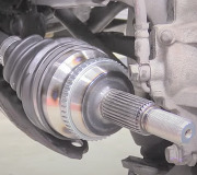
AXLE SHAFT
NOTE:With axle shaft removed and axle shaft nut NOT tightened to specification, ensure vehicle weight DOES NOT rest on wheel bearings and hub.
Removal
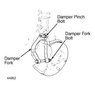
Raise and support vehicle. Remove front wheels. Drain transaxle fluid. On Legend, it is not necessary to drain transaxle fluid if removing left axle shaft only. On all models, remove lock tab from axle shaft nut and remove nut. Remove damper pinch bolt and damper fork bolt. Remove damper fork. See Fig. 1 .
Remove lower ball joint cotter pin and loosen castle nut half the length of the ball joint threads. Using a ball joint puller, separate ball joint from front hub. Remove ball joint castle nut. Lower control arm and steering knuckle. Pull steering knuckle outward and remove axle shaft from hub assembly. Use a plastic hammer to drive axle out of hub if necessary.
NOTE:DO NOT pull on inner CV joint or disassembly may occur. Be careful not to damage seals.
Using a large screwdriver, carefully pry the inner CV joint and shaft assembly approximately .5" (12.7 mm). This will dislodge the retaining ring from the groove at end of the drive axle. Grip both sides of the inner CV joint and remove the axle shaft and CV joint from vehicle.
NOTE:DO NOT disassemble the outer CV joint, as this must be replaced as an assembly. On inner CV joint, mark rollers and roller grooves to ensure exact reassembly.
Fig. 1: Locating Damper Fork & Pinch Bolt
Courtesy of AMERICAN HONDA MOTOR CO., INC.
Disassembly
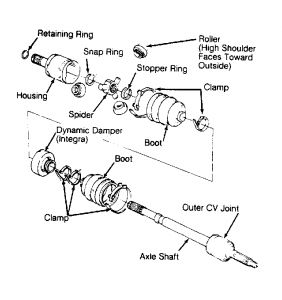
Remove axle shaft from vehicle and place on work bench. Remove inner CV joint boot clamps and discard. Slide boot toward the outer CV joint to access inner CV joint. See Fig. 2 .
Index axle shaft, inner CV joint housing and spider roller to ensure reassembly to original location and position. Remove housing from spider assembly. Index rollers and spider to ensure reassembly to original location. Remove rollers from spider.
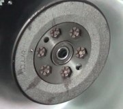
Remove snap ring securing spider to axle shaft and remove spider. Remove stopper ring and slide boot off axle shaft. Remove outer CV joint boot clamps. Slide boot off axle shaft's inner CV joint end. DO NOT disassemble outer CV joint. Replace outer CV joint as an assembly only.
Reassembly
Thoroughly clean and inspect axle shaft for wear. Replace all defective parts. Wrap axle shaft splines with vinyl tape to prevent damage to dynamic damper (Integra only) and CV joint boots.
Install outer CV joint boot, dynamic damper (Integra models) and inner CV joint boot. Remove vinyl tape from axle shaft. DO NOT install CV joint boot clamps at this time.
Install stopper ring in groove on axle shaft. Install spider on axle shaft by aligning marks made at disassembly. Install snap ring into groove. Pack outer CV joint boot with molybdenum disulfide grease. Lube spider and inside bore of rollers.
Ensure rollers are aligned with marks made at disassembly and high side of rollers are facing outward. Install rollers. Pack inner CV joint and boot with molybdenum disulfide grease. Align housing marks made at disassembly and install housing on spider assembly. Adjust standard length of axle shaft. See Fig. 3 and Fig. 4 . Position boots halfway between full compression and full extension and install new boot clamps.
Lightly tap doubled-over portion of boot clamp to reduce clamp height. Install a new retaining ring on end of inner CV joint and install axle shaft.
CAUTION:Always use a NEW retaining ring when installing axle shaft.
Fig. 2: Exploded View of Axle Shaft
Courtesy of AMERICAN HONDA MOTOR CO., INC.
Installation
Measure the assembled axle shaft and ensure length is within specifications. See Fig. 3 or Fig. 4 . On Integra models, install damper to specified position. See Fig. 5 . On all models, install a new retaining ring in groove at end of axle shaft. Install new clamps on boots.
Slide axle into transaxle or intermediate shaft. Ensure retaining ring seats fully in groove. Check by attempting to pull axle out of installed position.
Pull hub assembly away from axle shaft and slide axle into hub assembly. Install axle shaft nut and lightly tighten. Position ball joint in hub. Raise lower control arm with floor jack and install ball joint nut. Tighten ball joint nut to specification. See TORQUE SPECIFICATIONS .
Install cotter pin and secure. Remove floor jack. Tighten axle shaft nut to specification. See TORQUE SPECIFICATIONS . To complete installation, reverse removal procedure.
Saturday, November 22nd, 2008 AT 4:12 PM