Hi and thanks for using 2CarPros.com.
Based on the code, a C1165 tells me there is a problem with the right rear ABS sensor. Chances are it is the sensor itself. Here are the directions for testing the system. They are extensive.
XT100-016
MODEL
X-TYPE
DATE
07 Dec 2006
SECTION: 100-00 - GENERAL INFORMATION
Wheel Speed Sensor Concerns Diagnosis
AFFECTED VEHICLE RANGE:
X-TYPE
VIN:
C00001 onwards
Model Year:
2002 onwards
CONDITION SUMMARY:
DIAGNOSTIC GUIDANCE FOR WHEEL SPEED SENSOR FAULTS
Situation:
This bulletin has been issued to provide diagnostic guidance for wheel speed sensor faults.
Action:
Should a wheel speed sensor fault arise, refer to the Repair Procedure detailed in this bulletin to resolve the concern.
PARTS:
No parts provided for this bulletin. Diagnostic information only.
WARRANTY:
No warranty necessary for this bulletin. Diagnostic information only. Normal warranty policy and procedures apply.
REPAIR PROCEDURE
CLASSIFICATION OF WHEEL SPEED SENSOR FAULTS
NOTE :Wheel speed sensor faults are classified as either "electrical faults" or "signal faults" and will indicate a potential problem as follows:
^ Electrical faults indicate a problem with the wheel speed sensor electrical circuit. The problem may be with the sensor, the control module or the wiring between the speed sensor and the control module. Warranty analysis indicates that the wiring is the most likely source of wheel speed sensor electrical faults.
^ Signal faults indicate that there is no detectable fault with the wheel speed sensor circuit but there is an abnormality with the signal from the sensor. The abnormality may be in the form of an implausible change in signal level, as a step or a spike, or it may be that it is at an implausible level compared to other wheel speed signals, for example, one signal may remain at zero while the others show a normal road speed.
NOTE :After fixing some wheel speed sensor faults, it will be necessary to drive the vehicle above a speed of 10 mph (16 kph) in order to extinguish the ABS warning lamp.
NOTE :A Midtronics battery charger PSC550 must be connected to the vehicle battery during diagnostic sessions.
1. Connect the diagnostic equipment to the vehicle and begin a WDS or IDS session.
NOTE :DTCs and snap shot data should be noted at all stages during the diagnosis. This information will be needed in the event further assistance is requested from Jaguar Technical Helpline.
2. Note DTCs and collect snap shot data.
NOTE :Where there is a combination of electrical faults and signal faults, the electrical faults should be corrected before investigating the signal faults. Correcting the electrical fault may also resolve a signal fault.
3. If no 'electrical faults' have been logged, proceed to the SIGNAL FAULT DIAGNOSTIC GUIDELINES section of this bulletin.
ELECTRICAL FAULT DIAGNOSTIC GUIDELINES
NOTE :Wheel speed sensor faults may be either "permanent" or "intermittent". Intermittent faults can be difficult to find but are usually caused by wiring or connector issues. If a wheel speed sensor Anti-lock Braking System (ABS)/Dynamic Stability Control (DSC) module fault is intermittent, it is highly unlikely that the cause of the fault is the ABS/DSC module.
A fault may be determined to be either "permanent" or "intermittent" by using the diagnostic tool to clear the Diagnostic Trouble Code (DTC) and carrying out an ignition reset.
1. Determine if a DTC is 'permanent' or 'intermittent' as follows:
^ Clear the DTC.
^ Carry out an ignition reset.
^ If the fault immediately returns on the next ignition reset, and if it is the only fault that returns, the fault is 'permanent' and the control module should be replaced.
NOTE :Wiring damage includes any signs of fatigue, rubbing, stretching or brakes. Damage to the wire insulation only is included as this can allow water into the wheel speed sensor head.
2. Carry out a detailed visual inspection of the wheel speed sensor cable from the point it connects to the sensor to the point it connects to the body or link harness.
3. If any damage is found, replace the wiring and sensor.
4. Disconnect each connector between the ABS/DSC module and the suspect wheel speed sensor and perform the following checks:
^ Check connectors for signs of pin corrosion, water ingress or damage.
^ Check that the pins are not bent or backing out.
^ Lightly pull the wheel speed sensor wires from the back of each connector to ensure they are securely crimped to the pins.
5. Reconnect all connectors and check to see if the DTC will clear.
6. Verify that a wheel speed sensor is working correctly by performing the following:
^ Disconnect the suspect sensor and a non-faulting sensor from respective wheels.
^ Electrically connect the suspect sensor to the wheel of the non-faulting sensor.
^ Carry out an ignition cycle (ignition on/off) and use the diagnostic tool to read the fault memory.
^ If an 'electrical fault' DTC has been logged for the wheel to which the suspect sensor has been connected, the sensor should be replaced.
7. Disconnect the ABS/DSC module connector and the connector closest to the wheel speed sensor.
8. Carry out wiring integrity tests (continuity, short-circuit, short-to-ground and short-to-power) on the wiring between the two connectors.
9. If a fault is 'intermittent', 'wiggle' the wires/cable harnesses, where they are accessible, and search for intermittent breaks/shorts.
10. If no faults were found and the wheel speed sensor fault was determined to be 'permanent' in step 1, the ABS/DSC module should be replaced.
11. If the fault is 'intermittent' and the wheel speed sensor was verified to be OK in Step 6, replace connector pins and link harnesses, where possible, in the wheel speed sensor circuit, as the likely root cause of the fault is an intermittent wiring or connector fault.
SIGNAL FAULT DIAGNOSTIC GUIDELINES
NOTE :Wheel speed sensor signal faults can be caused by sensor installation issues, wiring issues, or even vehicle behavior.
NOTE :A wheel speed sensor signal fault will clear and not return after a normal test drive if the fault was a result of either of the following situations:
^ Individual wheels or pairs of wheels having been rotated independently of the others, such as when the wheels have been driven while the vehicle is on a wheels-free ramp.
^ A loss of traction on one or more wheels for extended periods.
1. Check that the vehicle has the correct wheel and tire sizes and that the tires are properly inflated.
2. If any discrepancies were found, correct and re-test.
3. Visually inspect to ensure that the sensor is correctly installed and seated.
4. If the encoder ring is visible, check that it is clean and that none of the teeth are damaged.
5. If the encoder ring is installed in the wheel bearing, and there is no excessive play in the bearing, remove the bearing and check the encoder ring for contamination or damage.
6. Check the sensor lead for any signs of damage to the outer insulation.
7. Check the sensor lead connector for damage or any signs of water ingress.
8. If any faults were found, correct and re-test.
9. If the diagnostic tool supports a data logging application, perform the following:
Set up to monitor the output from all four wheel speed sensors during a road test.
NOTE :As the vehicle speed increases from stand still, all four signals should rise simultaneously and show the same output, within an average of +/- 1.2 mph (+/- 2 kph). There should not be any random or regular signal spikes or deviations on individual signals.
^ Test drive the vehicle slowly at approximately 10 mph (16 kph) in a straight line on a smooth road.
^ Check for any random spikes/deviations occurring on any individual signal that will indicate an electrical fault.
^ Check for any regular spikes/deviations occurring on any individual signal that will indicate a problem with the sensor encoder ring.
10. Perform the following integrity checks on the wiring between the sensor connector and the control module connector:
^ Check for shorts to power or ground.
^ Check for signs of corrosion or water ingress into the connectors.
^ Check for any cuts or abrasions in the wiring insulation, where possible.
11. Disconnect and re-connect all connectors between the ABS/DSC module and the suspect wheel speed sensor and check to see if the DTC clears.
12. Determine if the root cause of the problem is the sensor as follows:
^ Swap the left-hand and right-hand sensors on an axle.
^ Test drive the vehicle above a speed of 10 mph (16 kph).
^ If the fault moves with the sensor, the sensor is faulty.
13. If no faults have been found, clear all DTCs and take the vehicle on a test drive of at least 10 miles (16km) above a speed of 10 mph (16 kph).
14. If there are no faults, the vehicle can be returned to the customer.
______________________________
Here are general directions for replacing a sensor:
https://www.2carpros.com/articles/how-to-replace-an-abs-wheel-speed-sensor
______________________________
Here are the directions specific to your vehicle:
2003 Jaguar X-Type (X400) V6-2.5L
Vehicle » Brakes and Traction Control » Sensors and Switches - Brakes and Traction Control » Wheel Speed Sensor » Service and Repair » Rear Wheel Speed Sensor
REAR WHEEL SPEED SENSOR
Removal
Remove the rear seat cushion.
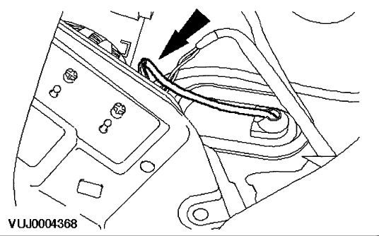
Disconnect the rear wheel speed sensor electrical connector.
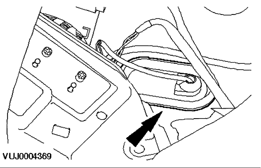
Detach the grommet.
Raise and support the vehicle.
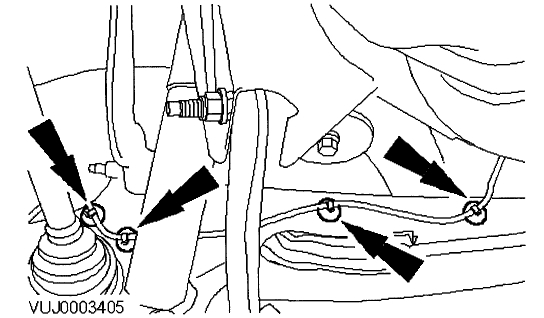
Detach the ABS wheel speed sensor wiring harness.
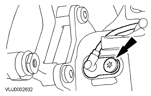
Remove the ABS sensor.
Installation
To install, reverse the removal procedure.
Tighten to 22 Nm.
________________________________________________
The attached pictures correlate with these directions.
I hope this helps. Let me know if you have other questions.
Note: Remember, this is the right rear sensor that is causing the problem. That would be the passenger side of the vehicle.
Take care,
Joe
Images (Click to enlarge)
Jun 7, 2018 at 9:29 PM