Are two of the A/C relay terminals supposed to be hot when car is in off position, or one terminal hot (battery voltage) and one cold?

Tiny
NJMCLAIN
  • MEMBER
  • 2005 SUBARU OUTBACK
  • 3.0L
  • 6 CYL
  • 4WD
  • AUTOMATIC
  • 90,000 MILES
I've attached the wiring diagram for review. (F27) 31 is hot when the car is off, 28 is cold (but 28 gets voltage when the car is in On position).

Thanks!
Sunday, May 7th, 2023 AT 12:49 PM

39 Replies

Tiny
STEVE W.
  • MECHANIC
  • 12,998 POSTS
Okay, terminal 29 takes power from the relay to the A/C clutch. Terminal 28 is constant power from fuse 22. Terminal 30 is the relay control signal from the PCM. Terminal 31 runs on power that comes from fuse 22 as well and from there through the A/C pressure switch, if the is a refrigerant charge in the system that switch should be closed. So, you should have power at terminal 28 and 31. As they get power from the same fuse. Follow the highlighted path.
Was this
answer
helpful?
Yes
No
Sunday, May 7th, 2023 AT 7:54 PM
Tiny
NJMCLAIN
  • MEMBER
  • 23 POSTS
Thanks, Steve.
Terminal 28 currently only has power when the ignition is in the 'On' position.
If I jumper 28 and 29, the compressor will run and blow cold.
Should I be looking for a short between 28 (in the engine bay) and fuse 22 (in driver side dash)?
Was this
answer
helpful?
Yes
No
Monday, May 8th, 2023 AT 6:48 AM
Tiny
NJMCLAIN
  • MEMBER
  • 23 POSTS
Additionally, I back probed the ECM (engine control module) at the terminal for the AC relay and while it has battery voltage when the car is off (correct reading), it also has voltage when the car is running and the AC is switched on (bad reading, should be 0v when A/C is engaged). Trying to determine if the ECM is bad or I have a wiring problem between 28 and fuse 22. I appreciate your help.
Was this
answer
helpful?
Yes
No
Monday, May 8th, 2023 AT 6:57 AM
Tiny
STEVE W.
  • MECHANIC
  • 12,998 POSTS
I dug around a bit and found an error in the diagrams. Fuse 22 should be switched power So both pins 28 and 31 should have power only when the key is on. If you jumper 28 and 29 and the compressor works, I would check for switched power at terminal 31. That should have power at the same time as 28. If it doesn't go, find the pressure switch and jump between pins 1 and 2 in its connector. Do you have power at 31 now? If yes, the pressure switch is bad. If you do have power at terminal 31 but still no A/C then check if pin 30 shows a ground when the A/C is selected on at the control panel. If it doesn't then there may be a problem in the blue wire w orange stripe.
Was this
answer
helpful?
Yes
No
Monday, May 8th, 2023 AT 7:10 AM
Tiny
NJMCLAIN
  • MEMBER
  • 23 POSTS
I have continuity between 28 and fuse 22 (0.4 ohms), when key is in Off position 28 has 63.5mV, and 31 has 62.8mV.
With key power On (ac off), 28 and 31 both have 11.94v. With power On(ac on) both show 11.7v.
Was this
answer
helpful?
Yes
No
Monday, May 8th, 2023 AT 7:23 AM
Tiny
NJMCLAIN
  • MEMBER
  • 23 POSTS
30 shows no ground with power on and ac switched on.

In previous testing terminal 33/connector 135 on ECM (ac relay control) showed battery power in the Off and power On (A/C Switched On) positions. I assume when the AC is switched on 33/135 on ECM is supposed to ground?
Was this
answer
helpful?
Yes
No
Monday, May 8th, 2023 AT 7:30 AM
Tiny
STEVE W.
  • MECHANIC
  • 12,998 POSTS
Sounds like the power side is okay and it has some charge because if the system was empty, it would drop the power at terminal 31 as the pressure switch would open. So now you need to determine if the ECM is the issue. With the readings you had from testing, pull the A/C relay and use a test light connected to battery power. Turn the A/C on max cold and touch pin 30 in the relay socket. If the light comes on the ECM is switching properly, if it doesn't and your earlier test showed it has continuity then we need to verify the powers and grounds for the ECM. Attached are the diagrams for those grounds.
Was this
answer
helpful?
Yes
No
Monday, May 8th, 2023 AT 7:45 AM
Tiny
NJMCLAIN
  • MEMBER
  • 23 POSTS
Battery-powered test light at Relay 30 is negative with car started and ac on max cold.

Continuity between Relay 30 and ECM B135 33 is good (0.9 ohms).

All ECM grounds listed show continuity (1.2 ohms), including GND Power Supply (B135 1 and 4).

Possibly not relevant here, but ECM B136 35 (Sensor GND) not showing continuity, but perhaps due to sensor not being on and system not plugged in?
Was this
answer
helpful?
Yes
No
Monday, May 8th, 2023 AT 8:43 AM
Tiny
STEVE W.
  • MECHANIC
  • 12,998 POSTS
So, pin 35 in B136 is a floating ground that goes to joint connector A and if it fails you will know it, the car wouldn't start or run.
So, you show continuity between 30 and the ECM but the ECM won't activate the A/C.
A couple more things to look at. There are two sensors (ambient air and interior air temp) that can tell the ECM not to run the /AC. Basically, those can tell the ECM that it's already colder than the temperature selected and not to run the A/C. The first two are the interior, it's in the dash next to the center stack. It can get clogged with crud or just fail. Testing it involves gaining access to it or to the AC control module behind the right side dash. To access it you remove the side panel of the console, and the sensor and connector are right there. Testing is simple, it's a thermistor with the attached temperature curve. Simply measure the resistance across the pins. An even faster way would be to use a scan tool to access the A/C module and see what it reports as the ambient and interior temperatures. For the ambient temperature sensor, it is mounted behind the front bumper, if your car shows external air temperature and it's close to actual temperature then it should be okay.
These two can stop the A/C if you selected say 72 degrees but the interior sensor was disconnected with it an open circuit it will max out and show -40C as the temperature! Probably don't need A/C at that temperature. Ambient would show the same.
Was this
answer
helpful?
Yes
No
Monday, May 8th, 2023 AT 11:03 AM
Tiny
NJMCLAIN
  • MEMBER
  • 23 POSTS
Hi Steve,

For the interior air temperature sensor, I can access it directly, but if I can test via the A/C Control Module, I'd prefer that as it's currently accessible. What would be the method for testing the interior temperature sensor via the A/C Control Module?

Exterior temperature sensor is within 3° of the actual temperature.
Was this
answer
helpful?
Yes
No
Monday, May 8th, 2023 AT 11:16 AM
Tiny
STEVE W.
  • MECHANIC
  • 12,998 POSTS
Look at the diagram I attached above find the module and connector B282, in it are pins 5 (white with green) and 15 (blue) and measure the resistance between them. Compare that to the temperature curve above. So, say you measure 5200 ohms and it's 75 degrees out, the sensor is bad. Measure 1250-1275 ohms at 70 and it should be okay.
The issue then becomes that if the sensors test okay and the system pressures are enough that it should work but isn't then you will need a scan tool that can control the ECM and the A/C module, which would be the only way to determine which module isn't activating the A/C.
Was this
answer
helpful?
Yes
No
Monday, May 8th, 2023 AT 11:32 AM
Tiny
NJMCLAIN
  • MEMBER
  • 23 POSTS
Thanks, Steve.
282 15 has no continuity to chassis ground.
Looks like 5 components directly connected to that ground:

Interior Temperature Sensor
Evaporator Sensor
Mode Actuator
Air Mix Actuator (x2)

Will begin diagnostic flows.
Was this
answer
helpful?
Yes
No
Monday, May 8th, 2023 AT 12:15 PM
Tiny
STEVE W.
  • MECHANIC
  • 12,998 POSTS
No rush. Oh, does everything else appear to be operating okay and it's just the A/C that doesn't? If so, I would sort of suspect the controller more than the ECM but without digging in with a scan tool and scope, I can't say that with 100% authority.
Was this
answer
helpful?
Yes
No
Monday, May 8th, 2023 AT 1:15 PM
Tiny
NJMCLAIN
  • MEMBER
  • 23 POSTS
The weather is heating up!

Everything else runs great, aside from no compressor engagement.

I pulled the same ac control module out of a car at the salvage yard and plugged it in and nothing happened.

FYI, my driver side air mix actuator was clicking for 6 months prior to the A/C failure. I took the car in to the dealer to get the actuator fixed when the A/C went down, and they waived me off and told me I needed a new compressor.
Was this
answer
helpful?
Yes
No
Monday, May 8th, 2023 AT 1:23 PM
Tiny
NJMCLAIN
  • MEMBER
  • 23 POSTS
Here's the current rundown:

Mode Actuator - Physically Operational
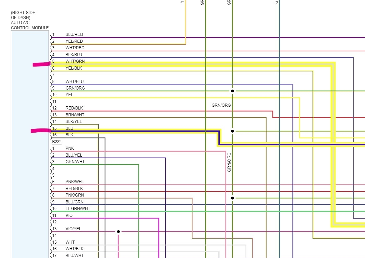
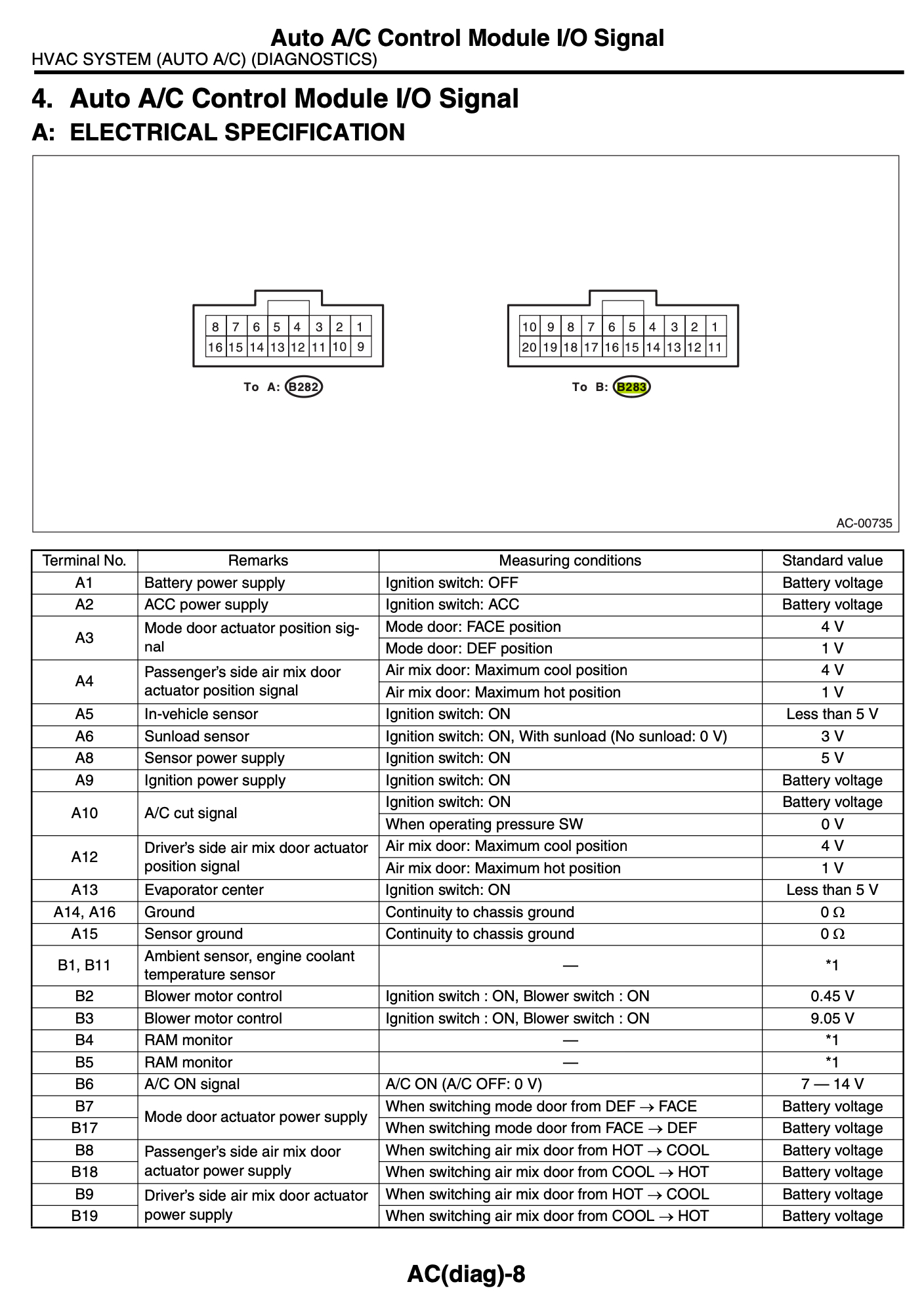
†Sensor Power Supply - (B282) 8 to 15: 4.9v
†Actuator Power Supply 1 - (B283) 7 to Chassis GND: 10v then cuts to 0.5v
†Actuator Power Supply 2 - (B283) 17 to Chassis GND: 10v then cuts to 0.5v
†All 5 harness connections btwn (B77) & (B282) have continuity
†Position Switch Signal - (B282) 3 to 15 shows appropriate voltage change when switching btwn DEF & FACE

Air Mix Door Actuator (x2) - Physically Operational (Both)
†Position Switch Power Supply - (B282) 8 to 15: 5v
†Actuator Power Supply 1 - (should be 7v)
Driver Side (B283) 9 to Chassis GND: Shows 10.7v then drops to 0.5v
Passenger Side (B283) 8 to Chassis GND: Shows 10.7v then drops to 0.5v (got it to read 8.3v steadily one time)
†Actuator Power Supply 2 - (should be 7v)
Driver Side (B283) 19 to Chassis GND: Shows 10.7v then drops to 0.5v
Passenger Side (B283) 18 to Chassis GND: Shows 10.7v then drops to 0.5v
†Continuity to be tested. Driver's Side Actuator is buried under the dashboard (can continuity test passenger side if needed)
†Position Switch Signal -
Driver Side (B282) 12 to 15 : Good
Passenger Side (B282) 4 to 15: Good

Interior Temp Sensor - Seems Operational
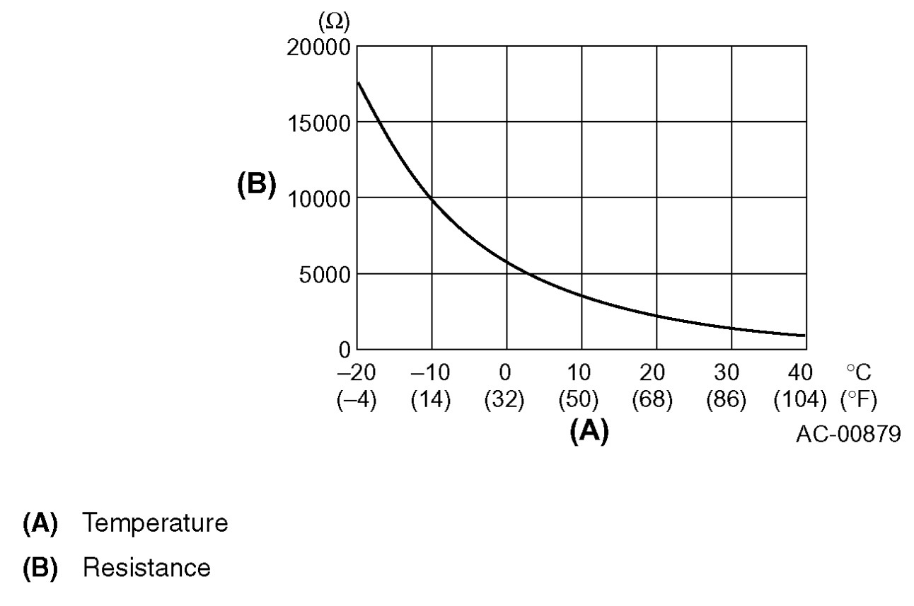
†1.75kV at 75°f
†Input Signal - (i55) 2 to 1: 3.5v (should be 5v)
†AC Control Module Output Signal - (B282) 5 to 15: 3.5v (should be 5v)
†Continuity - (i55) 2 to (B282) 5 & (i55) 1 to (B282) 15: 0.5 ohms each
Was this
answer
helpful?
Yes
No
Monday, May 8th, 2023 AT 8:32 PM
Tiny
NJMCLAIN
  • MEMBER
  • 23 POSTS
The resistance of the interior temp sensor itself is nearly identical (a bit higher) than the resistance of temperature sensor wiring harness (i55) 1 to 2. Not sure if that is helpful.

When I previously tested voltage of the ECM AC Relay Control (B135) 33 to Chassis GND (with engine on an ac set to max cool) it showed 14.2v (should be 0v). Which is why I was considering it might be the ECM.

I'm going to try a known functioning A/C Control Module from a local mechanic and see if that does anything.

This is probably a bit more than you bargained for, Steve. I appreciate your time and knowledge.
Was this
answer
helpful?
Yes
No
Tuesday, May 9th, 2023 AT 7:33 AM
Tiny
STEVE W.
  • MECHANIC
  • 12,998 POSTS
More data makes it easier in most cases. The signal wire staying at battery voltage means the ECM either isn't getting the signal to turn on the clutch, is being told not to, or it cannot internally. That is the question now. Which of the three is it. If you were to jumper that pin to ground the AC should function, but without any control. By testing the aspirator and ambient temperature you eliminated those, you already know the compressor will turn on and cool as well. That leaves the ECM and the control head. Both which communicate on the CAN to transfer that data. This would be when a scan tool would help, if you turn the A/C on and the scan tool shows that the ECM received that data, but the relay stays off, it's a bad driver in the ECM. If you turn it on but the ECM doesn't show it, it's likely the control head.
Now if you had a 94 or even 2004 version of this it would be much easier, they didn't stick everything in a module and make it hard to test.
Was this
answer
helpful?
Yes
No
Tuesday, May 9th, 2023 AT 11:58 AM
Tiny
NJMCLAIN
  • MEMBER
  • 23 POSTS
Evaporator sensor is reading 1.2k ohms @ 78f

If I unplug the evaporator sensor connector, and short (B282) 13 to 15, would that effectively bypass the sensor? Or is the sensor sending more complicated data vs an open/close signal?

Separately, should (B283) 6 (A/C Power On to ECM) have continuity to GND once power is applied? Currently cannot get continuity to chassis ground for (B283) 6. If that is the case would it point to an actuator or sensor input to the A/C control module being the culprit?
Was this
answer
helpful?
Yes
No
Tuesday, May 9th, 2023 AT 3:17 PM
Tiny
STEVE W.
  • MECHANIC
  • 12,998 POSTS
That Evap sensor tells the control head if the core freezes up. The 1.2K sounds about right for the resistance.
Pin 6 at the ECM is a simple voltage trigger key on it should be around ground with the A/C on, battery voltage with the A/C off. Here are the tests for the ECM with the 2 for A/C control highlighted. The info I have doesn't do this for the A/C module.
Was this
answer
helpful?
Yes
No
Tuesday, May 9th, 2023 AT 9:02 PM
Tiny
NJMCLAIN
  • MEMBER
  • 23 POSTS
.
Was this
answer
helpful?
Yes
No
Wednesday, May 10th, 2023 AT 6:32 AM

Please login or register to post a reply.

Sponsored links