Hi,
I will be happy to help. However, I need more information. What did the bearing look like that came out? Were they round? If you lift that wheel off the ground, is there play in the wheel which would indicate an axle/hub bearing. On the other hand, the CV joints also have ball bearings in them.
Was there a clicking sound prior to the incident? Also, when you place it in gear now, does it seem like it's in neutral? If so, then it's likely the CV joint. If there is a load on the engine and it just can't move the vehicle, something has come apart with the bearing.
As far as the other questions, I need you to start a new thread, one for each. We try to keep our threads specific to one topic so it helps others. I hope you understand.
I am going to provide the directions for the replacement of the hub bearing. However, the removal and replacement requires a press. This doesn't come as an assembly. The bearing is pressed into the steering knuckle.
The attached pics correlate with the directions.
___________________________
1999 Hyundai Elantra GLS Sedan L4-2.0L
Front
Vehicle Steering and Suspension Wheels and Tires Wheel Hub Service and Repair Procedures Front
FRONT
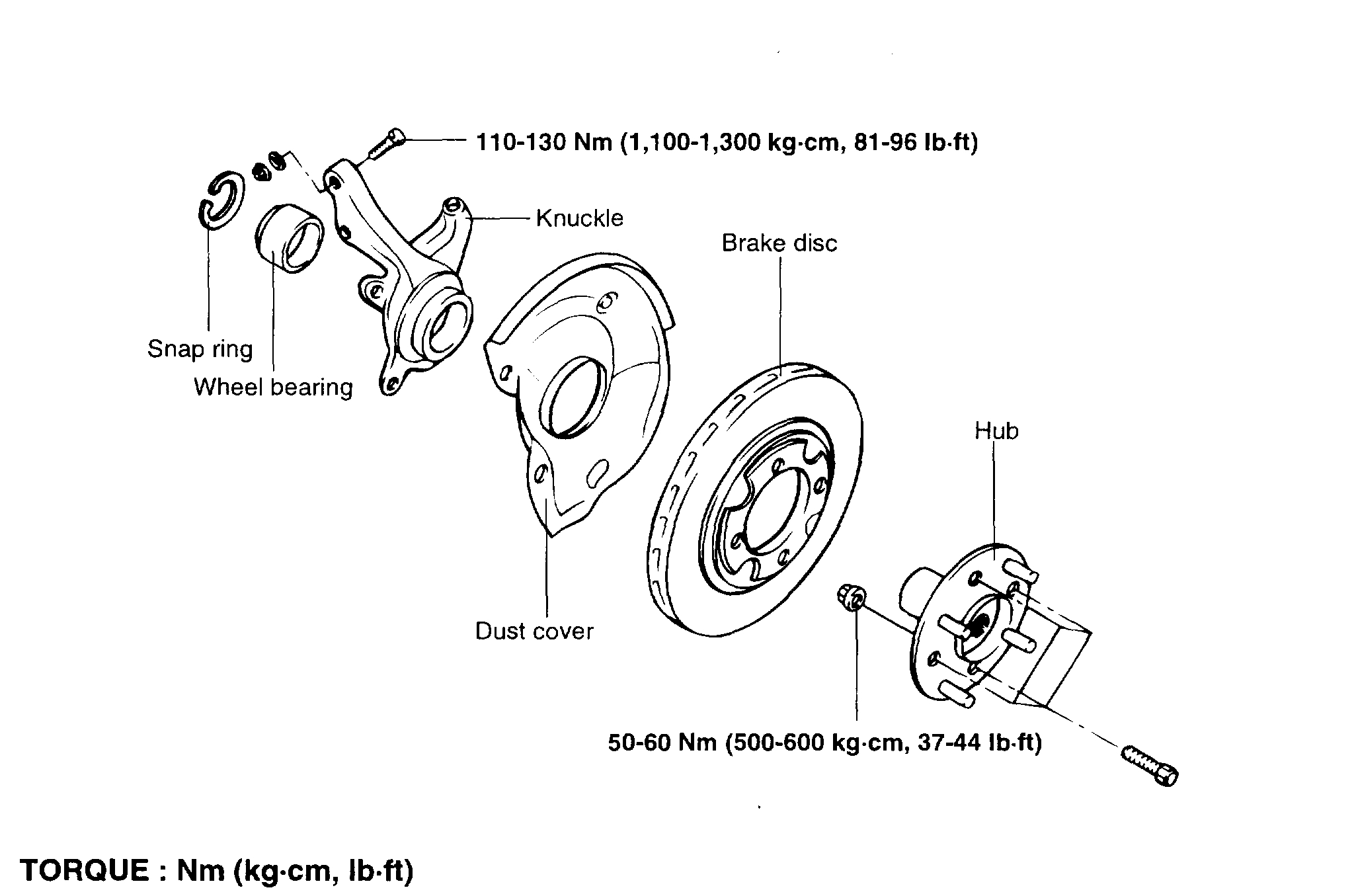
FRONT HUB/KNUCKLE
pic 1
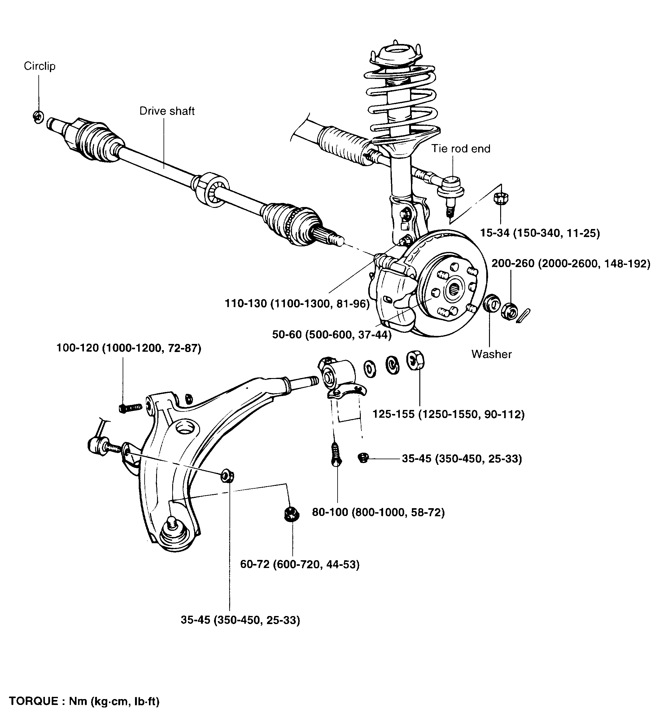
COMPONENTS
REMOVAL
1. Remove the wheel and tire.
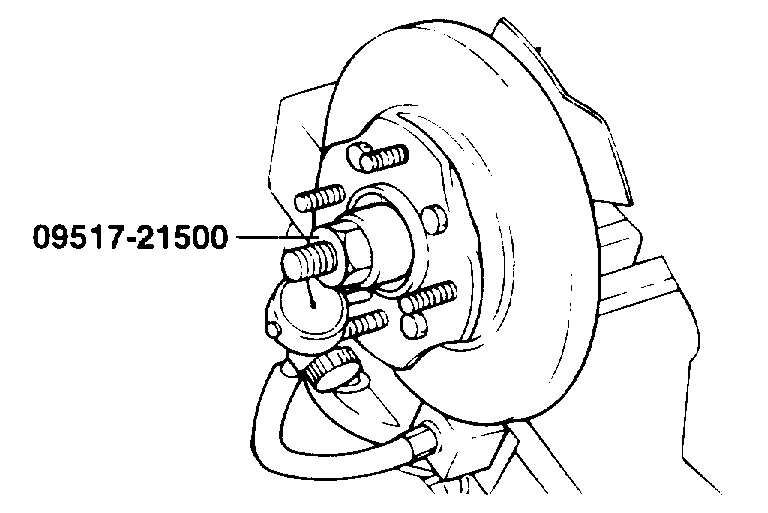
2. Remove the drive shaft nut.
Pic 2
3. Remove the vehicle speed sensor from the axle assembly.
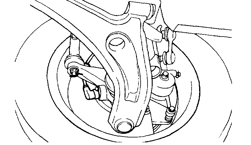
4. Remove the front brake assembly from the knuckle and suspend with a wire.
NOTE: Brake hose does not need to be disconnected from brake caliper. Be careful not to depress brake pedal, or piston will pop out.
Pic 3
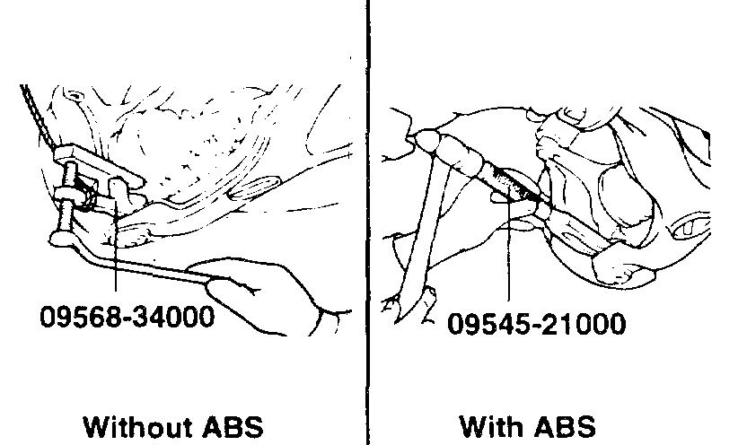
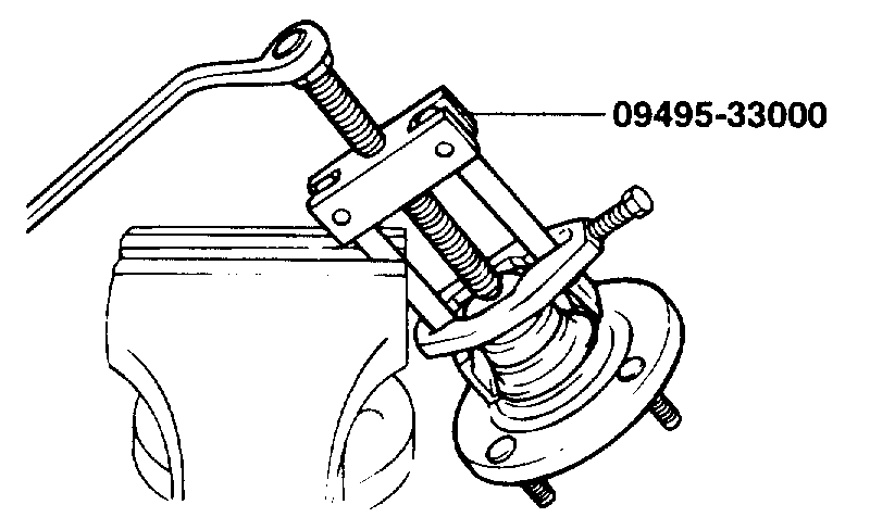
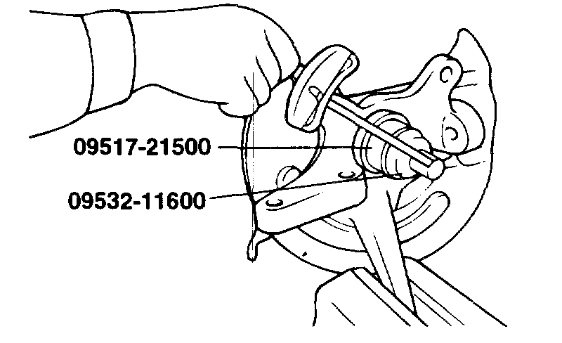
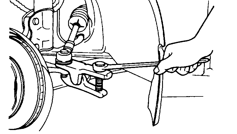
5. Disconnect the lower arm ball joint from the knuckle using the special tool.
Pic 4
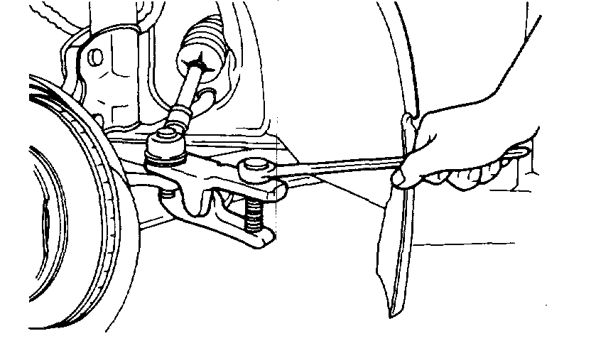
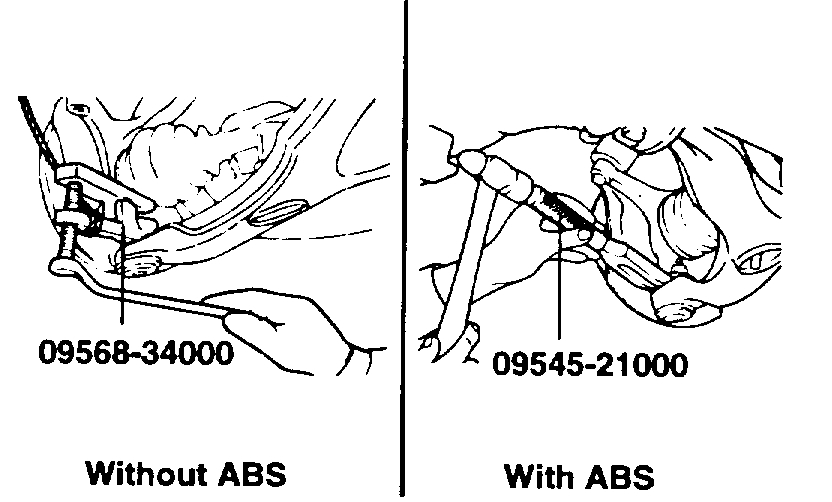
6. Disconnect the tie rod and ball joint from the knuckle using the special tool.
NOTE:
1. Be sure to tie a cord to the special tool and to a nearby part.
2. Loosen the nut but do not remove it.
Pic 5
7. Disconnect the drive shaft from the hub using the special tool.
Pic 6
8. Remove the hub and knuckle as an assembly from the strut.
INSPECTION
1. Check the hub for cracks and the splines for wear.
2. Check the snap ring for cracking or damage.
3. Check the steering knuckle for cracks.
DISASSEMBLY
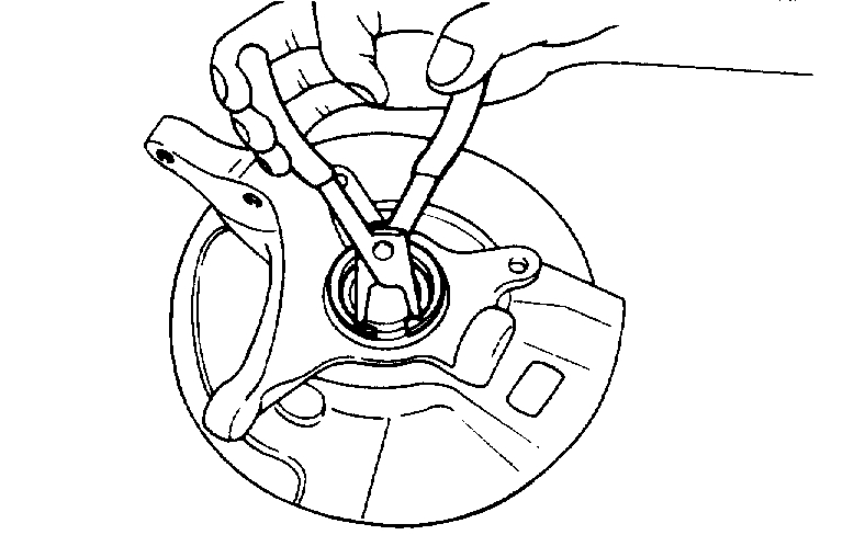
pic 7
1. Remove the snap ring.
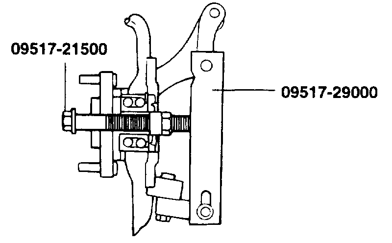
Pic 8
2. Attach the special tools to the knuckle and hub.
3. Secure the knuckle in a vise.
4. Tighten the nut of the special tool and remove the hub from the knuckle.
NOTE: When removing wheel hub or wheel bearing from knuckle, replace wheel bearing assembly (outer race, inner races and grease seals) with a new one.
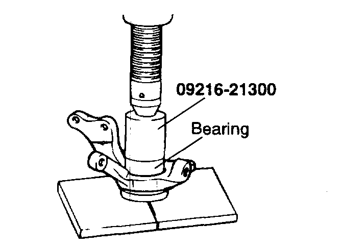
Pic 9
5. Using the special tool, remove the wheel bearing inner race (outside) from the front hub.
Pic 10
6. Install the inner race (outside) that was removed from the hub to the wheel bearing, and then use the special tool to remove the wheel bearing.
INSPECTION
1. Check the hub and brake disc mounting surfaces for scoring and contamination.
2. Check the knuckle inner surface for scoring and cracks.
3. Check for a defective bearing.
REASSEMBLY
1. Fill the wheel bearing with multipurpose grease.
2. Apply a thin coating of multipurpose grease to the knuckle and bearing contact surfaces.
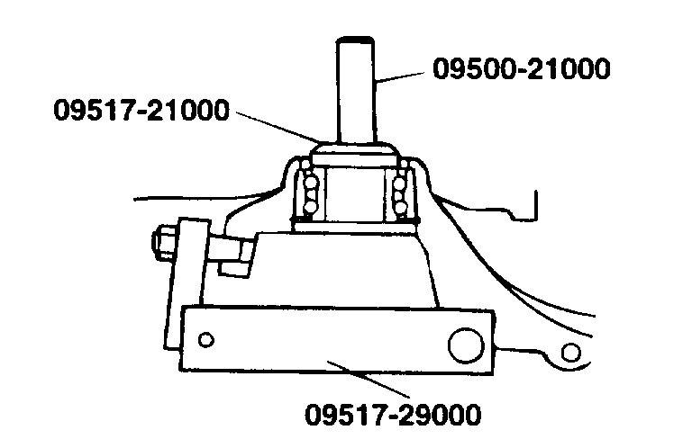
Pic 11
3. Press-in the bearing by using the special tool.
NOTE: Do not press inner race of wheel bearing assembly.
4. Install snap ring into groove of knuckle.
Pic 12
pic 13
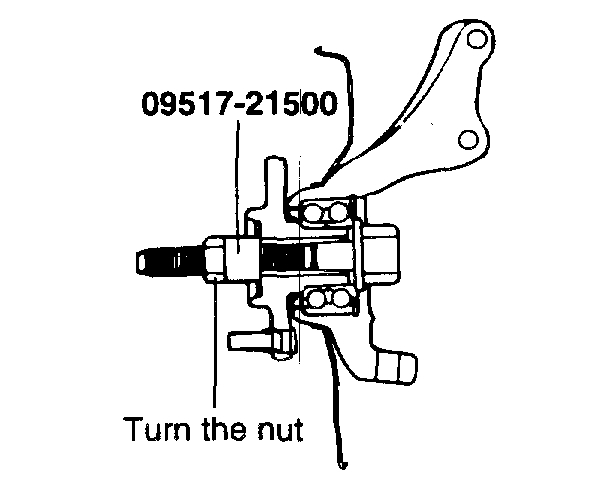
5. Measure the hub bearing starting torque.
Hub bearing starting torque [Limit] 1.3 Nm (13 kg cm, 12 inch lbs.) Or less.
Pic 14
6. If the starting torque is 0 Nm (0 inch lbs.), Measure the hub bearing axial play.
7. If the hub axial play exceeds the limit while the nut is tightened to 200 - 260 Nm (2,000 - 2,600 kg cm, 148 - 192 ft. Lbs.), The bearing, hub and knuckle have not been install correctly. Repeat the disassembly and assembly procedure.
Standard value:
Hub bearing axial play [Limit] 0.008 mm (0.0003 inch)
8. Remove the special tool.
INSTALLATION
1. Install parts to the torque specifications.
2. Be sure to install the washer and wheel bearing nut in the specified direction.
3. After installing the wheel, lower the vehicle to the ground and tighten the wheel bearing nut.
4. If the position of the split pin holes do not match, tighten the nut up to 260 Nm (2600 kg cm, 188 ft. Lbs.) Maximum.
5. Install the split pin in the first matching holes and bend it over.
_______________________________________
Here are the directions for replacing the axle shaft with new CV joints.
1999 Hyundai Elantra GLS Sedan L4-2.0L
Removal and Installation
Vehicle Transmission and Drivetrain Drive Axles, Bearings and Joints Axle Shaft Assembly Service and Repair Procedures Removal and Installation
REMOVAL AND INSTALLATION
FRONT DRIVE SHAFT
pic 15
COMPONENTS
REMOVAL
1. Lift up the vehicle and remove the tires.
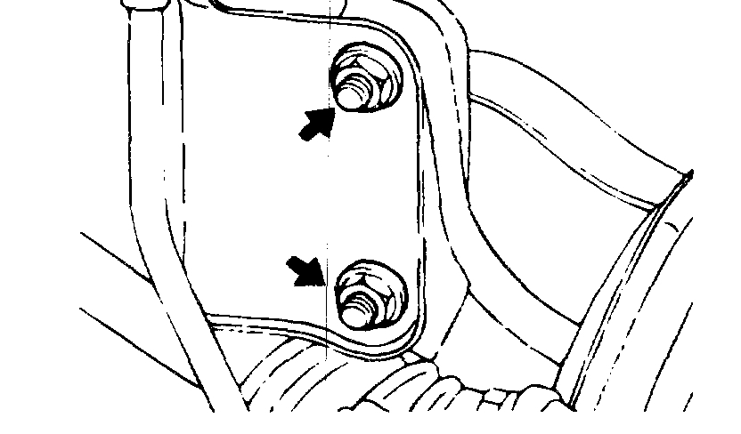
2. Drain the transaxle fluid.
Pic 16
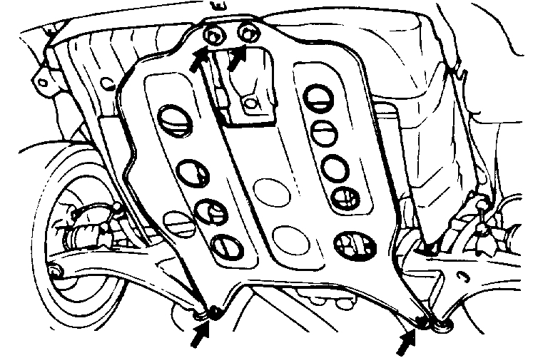
3. Remove the dust cover.
4. Remove the split pin and drive shaft nut from the hub.
5. Loosen the lower arm ball joint nut but do not remove it.
Pic 17
6. Using the special tool, disconnect the ball joint from the lower arm.
CAUTION: Be sure to tie a cord of the special tool to a nearby part.
7. Loosen the tie rod end nut but do not remove it.
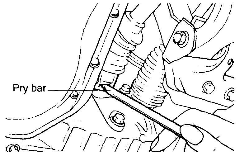
Pic 18
8. Using the special tool, disconnect the tie rod end from the knuckle.
NOTE: Be sure to tie the cord of the special tool to a nearby part.
Pic 19
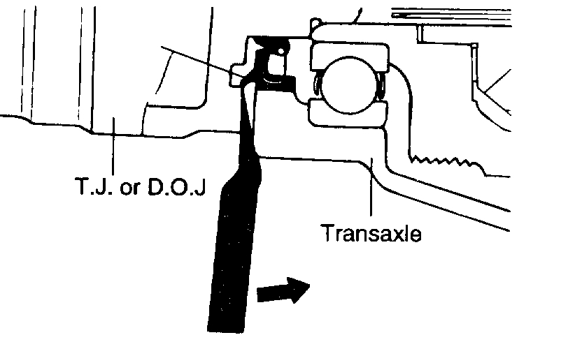
9. Insert a pry bar between the transaxle case and joint case (T.J or D.O.J), and pry the drive shaft from the transaxle case.
NOTE:
1. Be sure to apply the pry bar to the rib of the transaxle case.
2. Do not insert the pry bar to deep, as this may cause damage to the oil seal. [Max. Depth ; 7 mm (0.28 inch)].
Pic 20
NOTE: For automatic transaxle, there is a groove in the T.J. For inserting a pry bar.
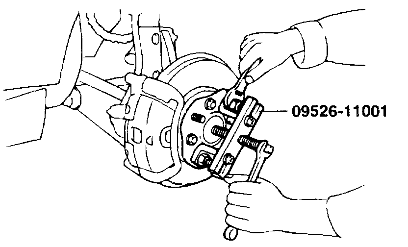
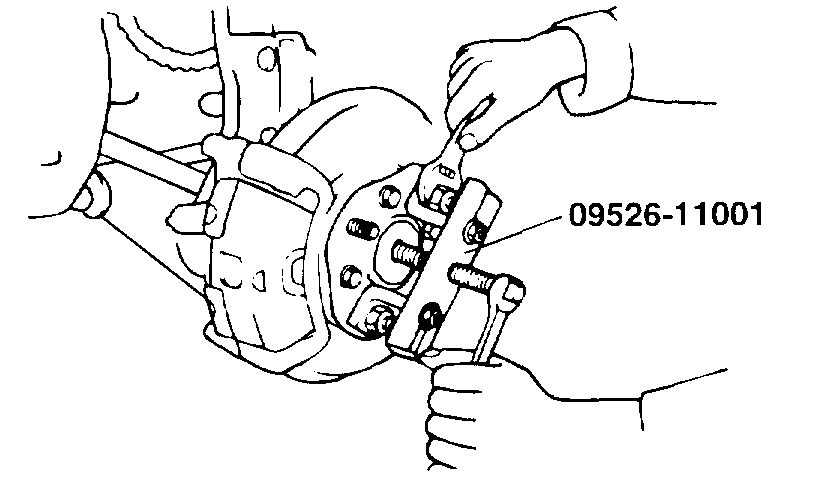
Pic 21
10. Using special tool (09526-11001), force the drive shaft out of the hub.
NOTE:
1. Place a plug in the hole of the transaxle case to prevent contamination.
2. Support the drive shaft properly.
3. Replace the retainer ring each time the drive shaft is removed from the transaxle case.
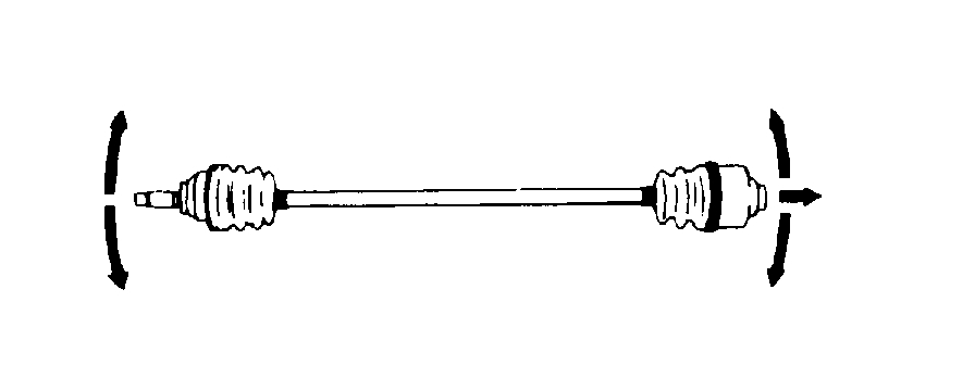
INSPECTION
pic 22
1. Check the drive shaft boots for damage and deterioration.
2. Check the ball joints for wear and operating condition.
3. Check the splines for wear and damage.
INSTALLATION
1. Coat gear oil to the drive shaft splines and differential case sliding surface.
2. Before installing the drive shaft, set the opening side of circlip facing downward.
3. After installation, check that the drive shaft cannot be removed by hand.
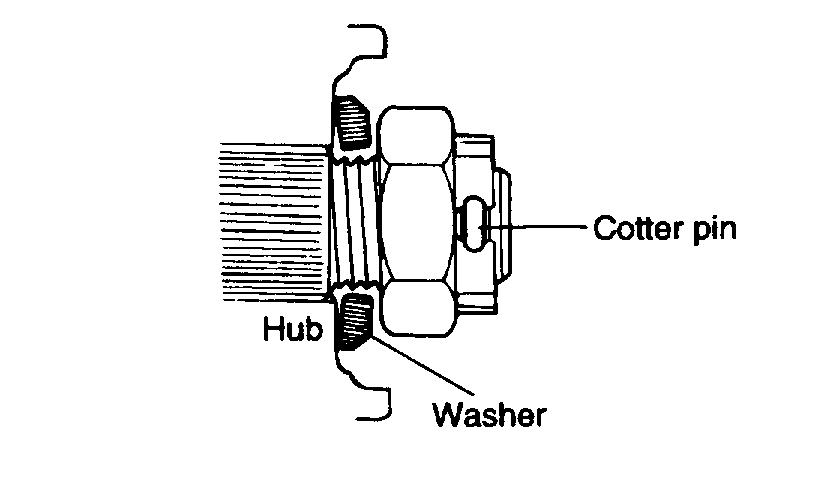
Pic 23
4. Install the washer under the drive outward as shown in the illustration.
5. Tighten the following parts to the specified torque.
Drive shaft nut 200 - 260 Nm (2000 - 2600 kg. Cm, 148 - 192 ft. Lbs.)
Low arm ball joint to knuckle 35 - 45 Nm (350 - 450 kg. Cm, 26 - 33 ft. Lbs.)
Tie rod end to knuckle 24 - 34 Nm (240 - 340 kg. Cm, 18 - 25 ft. Lbs.)
6. Install the under cover.
____________________________
Let me know if this helps. Also, let me know if you have any questions or need help.
Take care,
Joe
Images (Click to make bigger)
Sunday, November 8th, 2020 AT 3:48 PM