Third brake light not working?

Tiny
HBREESE
  • MEMBER
  • 2006 CHEVROLET COLORADO
  • 3.5L
  • 5 CYL
  • 2WD
  • AUTOMATIC
  • 133,000 MILES
In the past, I have never had an issue with the 3rd brake lights not working. I just became aware of this issue today when my truck failed the Texas state safety inspection. The truck is kept in a garage and rarely exposed to wet conditions.

I have done some fairly extensive basic troubleshooting and testing. Please read all I have considered and tests I have performed before jumping to diagnostic conclusions. I have a degree in electronics, so I do know how to correctly use a voltage and continuity tester to check circuits.

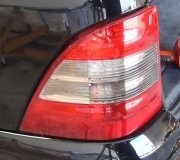
All of the brake lights in the rear taillights function correctly. The cab lights in the 3rd brake light function correctly. All 4 bulbs in the 3rd brake light are good (I checked them with a continuity tester and an independent 12v power source.) There is no corrosion or discoloration on any of the terminals for all 4 bulbs and also the main harness connector going into the cab of the truck behind the lamp assembly.

Using a continuity tester, I have successfully verified:
1. Continuity across the lamp and socket connectors.
2. Continuity across the wiring harness connectors.
3. Continuity from harness connector to chassis ground.
4. Continuity across all fuses in the fuse block under the hood.

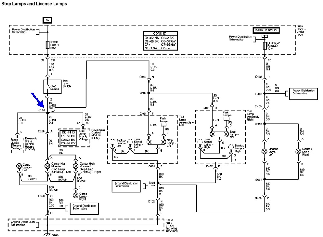
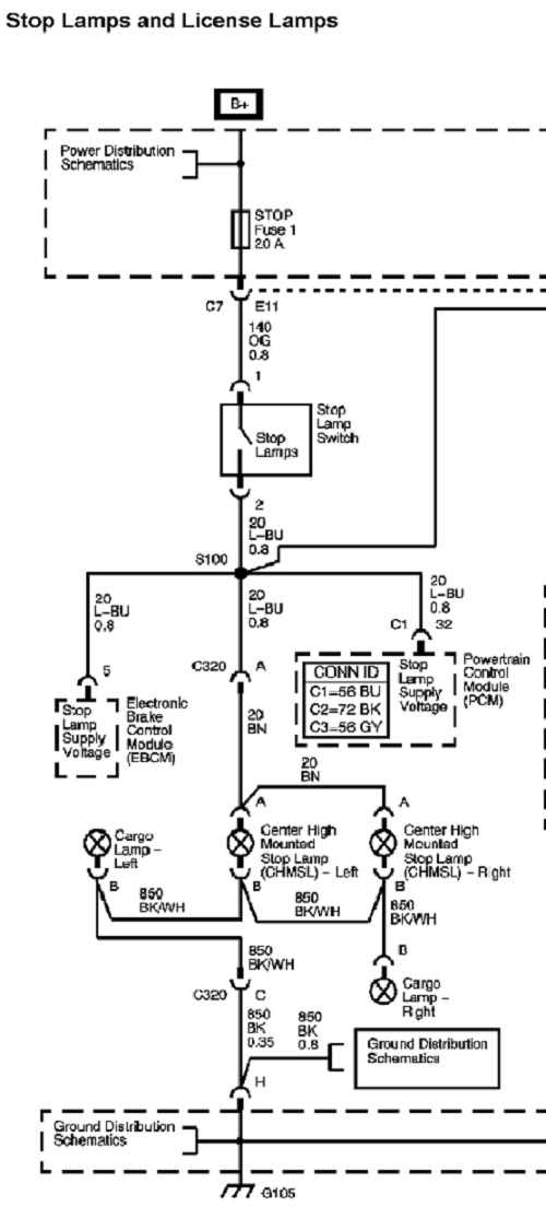
There is 0 voltage in the light blue wire at the main connector from the cab to the 3rd taillight harness when pressing down on the brake pedal. I have tested every fuse in the fuse block under the hood.

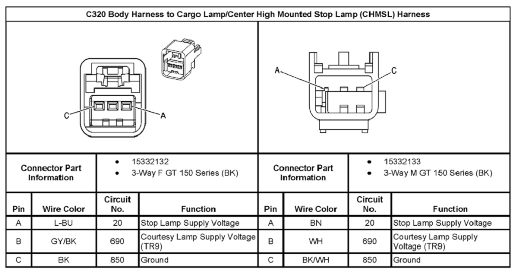
If I unplug the main connector from the cab to the third brake light assembly and connect 12v to the black/white wire and connect the brown wire to chassis ground, the brake lights will light. I have not tried connecting 12v with the harness connected from the cab to the light bar to make sure I don't cause any damage to the wiring circuit(s) or fuse(s).

The factory rubber 3rd brake light gasket is in good condition and there is no evidence any moisture or dirt has ever been inside the lamp housing. So, at this point, I feel like the lamp assembly and bulbs are in good working order.

Where should I look/test to find the missing/damaged connection causing 0 volts to the light blue wire coming out of the cab when the brake pedal is pressed?
Thursday, February 1st, 2024 AT 5:42 PM

2 Replies

Tiny
CARADIODOC
  • MECHANIC
  • 33,744 POSTS
I'm having a temporary glitch right now that won't let me in to our AllData service manuals, but I'd still like to work with you since electrical is one of my specialties. You're miles ahead of where most people would be in the diagnosis, but allow me to suggest a few ideas for now until I can look at a diagram.

The first thing I noticed is you're doing a lot of continuity checks. Those can identify a solid break, but often not one with high resistance. Next, putting 12 volts to a point in the circuit can tell you what works, but it takes a lot of work to do that. I mean dragging wires around and looking for good ground points that typically have a lot of paint on them.

My preferred method is to find where the circuit is getting 12 volts and following that until it is lost, but that has to be done with a load on that circuit. The biggest mistake I see that leads people down the wrong path is not having that load, or complete circuit.

I have a real good example of that. Back in the mid '90s at the dealership, a coworker asked me for help on an overheating Dodge K-car. He found the radiator fan motor was dead. After unplugging it, he used a scanner to activate the fan relay, and found 12 volts feeding the fan was pulsing on and off, as it was supposed to be doing with the scanner. The obvious solution was to replace the fan motor.

A few days later when the motor was installed, it was still dead, but he had the 12 volts going to it. He had checked the ground wire already. I asked if he was finding that 12 volts with a digital meter? "Yes". I told him to use a cheap incandescent test light instead. He looked at me like I was stupid, but a few minutes later he was back. No 12 volts with the test light.

To boil this sad story down, the old motor had developed tight bearings so it was drawing more and more current until the day it burned open the fuse link wire. Think of them as a slow-blow fuse. When they burn open, the last step is arcing inside the insulation. That leaves a residue of carbon behind. That carbon was more than enough for a tiny tickle of current to get through for the meter to falsely see 12 volts. Had he measured that while the motor was plugged in, he would have found 0 volts. With the test light, it provided the load and not nearly enough current could get through that carbon track to make it light up. This is where the cheap test light is more accurate than the expensive voltmeter.

My coworker was correct to replace the tight fan motor, but the rest of the repair was to solder in a new fuse link wire.

Now that I shred that wondrous story, see if you can take voltage readings in that circuit with everything plugged in. The bulbs will provide the load that makes a poor connection become apparent. If the connectors are sealed and you have to unplug them, use the test light instead of the meter. Continuity tests have the same shortcoming. The current they supply in the Ohms test is so small, all it would take is one tiny strand of wire still intact to get a reading of 0 ohms, but you wouldn't get enough current through that to run the bulbs.

Next, where are you finding those black / white and brown wires? Could you have their roles reversed? Typically the black / white would be a ground wire. Regardless, what I'm leading up to is GM is somewhat famous for running a wire harness under the carpet under the driver's foot area. That's a place where a lot of people find wiring problems, but to my knowledge, there's no connectors under there. If you're applying the 12 volts further back, you might consider looking under the carpet for wires that are rubbed through and / or corroded.

I'll be able to do a better job when I can look at a diagram. When that happens, I can post the diagram for you if you need it.
Was this
answer
helpful?
Yes
No
Thursday, February 1st, 2024 AT 6:51 PM
Tiny
CARADIODOC
  • MECHANIC
  • 33,744 POSTS
Okay, here's the diagram for your truck. We know everything is okay up to splice S100, (blue arrow), because the other brake lights are working. Connector C320 is in the middle and might be a good place to find test points and corrosion. They don't show its location, but I found this chart that lists it as being above the rear of the headliner.

In the last diagram, I blew up just the left half with the center brake lights. The black / white is the ground wire, and the light blue you found with the missing 12 volts is the 12-volt feed. The ground wire goes through C320 too, but it is shared with the cargo lamps. If those lamps work, the ground wire has to be okay.

Given the missing 12 volts, the next best suspect would be a corroded splice, S100. That is shown in the fifth image. It appears to be a part of the harness that runs along the bottom edge of the dash, right above the accelerator pedal.

These can be a little difficult to read. You can copy them into a typing program and expand them there. I use MS Word. I expanded the splice location a little in the last image.

See how far you get now and let me know what you find.
Was this
answer
helpful?
Yes
No
Friday, February 2nd, 2024 AT 3:20 PM

Please login or register to post a reply.

Sponsored links