Hi,
Basically, you have an open circuit between the sensor and the PCM. I am going to attach the diagnostic flow chart along with all the general information related to this code. Note that both codes deal with an open circuit.
2008 Saturn Aura V6-3.5L
P0010
Vehicle ALL Diagnostic Trouble Codes ( DTC ) Testing and Inspection P Code Charts P0010
P0010
DTC P0010
Diagnostic Instructions
* Perform the Diagnostic System Check - Vehicle (See: Vehicle > Initial Inspection and Diagnostic Overview) prior to using this diagnostic procedure.
* Review Strategy Based Diagnosis (See: Vehicle > Initial Inspection and Diagnostic Overview) for an overview of the diagnostic approach.
* Diagnostic Procedure Instructions (See: Vehicle > Initial Inspection and Diagnostic Overview) provides an overview of each diagnostic category
DTC Descriptor
DTC P0010
- Camshaft Position (CMP) Actuator Solenoid Control Circuit
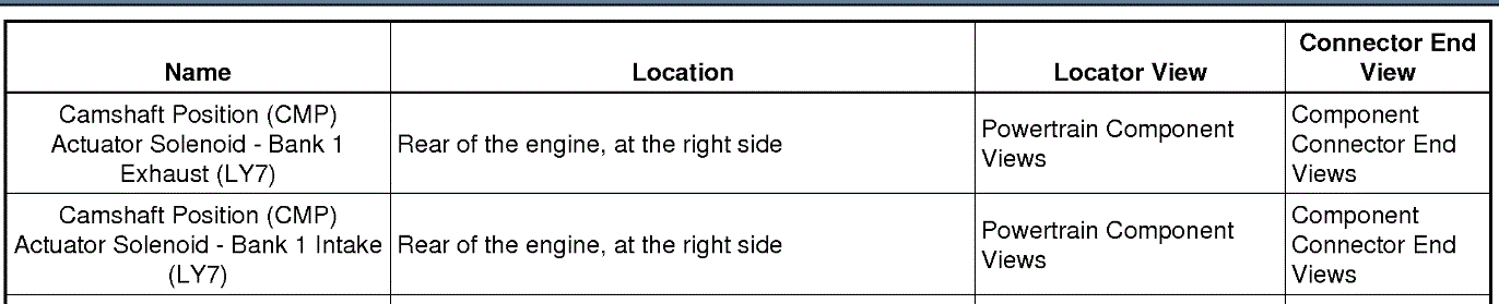
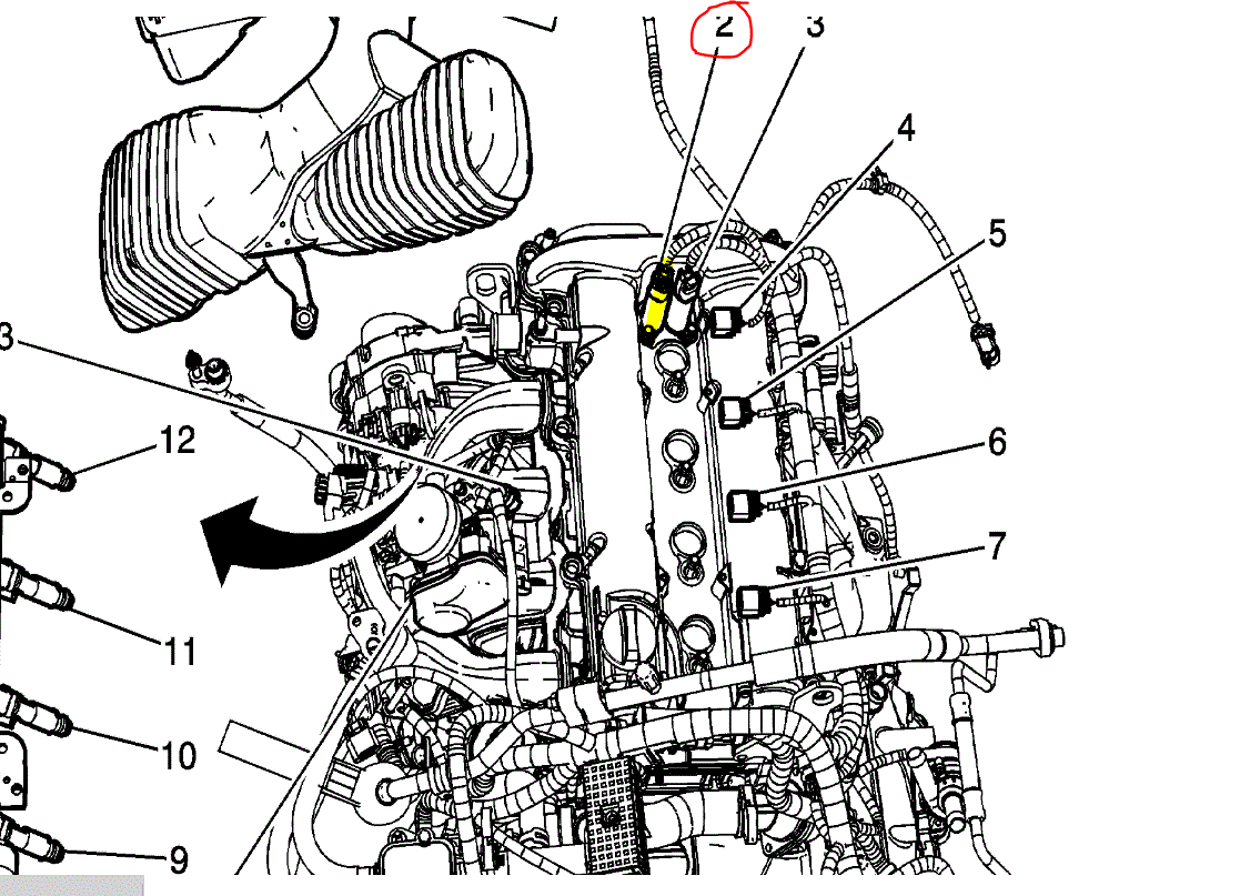
Diagnostic Fault Information
pic 1
Circuit/System Description
The camshaft position (CMP) actuator is attached to the camshaft and is hydraulically operated in order to change the angle of the camshaft relative to crankshaft position (CKP). The CMP actuator solenoid is controlled by the engine control module (ECM). The ECM sends a pulse width modulated 12-volt signal to a CMP actuator solenoid. The solenoid controls the amount of engine oil flow to the CMP actuator by extending a pintle within the solenoid. The pintle acts against a spool valve in the CMP actuator mechanism which is attached to the front of the camshaft. As the spool valve is moved, oil is directed to the CMP actuator, which rotates the camshaft. The CMP actuator can change the cam angle a maximum of 27 degrees.
Conditions for Running the DTC
* The ignition is in Crank or Run.
* The system voltage is between 11-18 volts.
* DTC P0010 runs continuously when the above conditions are met.
Conditions for Setting the DTC
The ECM detects that the state of the driver and the state of the circuit do not match. The ECM will detect an open, short to ground, or a short to voltage on the high control circuit or an open on the low reference circuit for more than 6.25 seconds.
Action Taken When the DTC Sets
* DTC P0010 is a Type B DTC.
* The CMP actuator is commanded to the home or parked position.
Conditions for Clearing the MIL/DTC
DTC P0010 is a Type B DTC.
Reference Information
Schematic Reference
Engine Controls Schematics (See: Powertrain Management > Electrical)
Connector End View Reference
Component Connector End Views (See: Vehicle > Connector Views)
Description and Operation
* Camshaft Actuator System Description ()
* Lubrication Description (See: Engine Lubrication > Components)
Electrical Information Reference
* Circuit Testing (See: Vehicle > Component Tests and General Diagnostics)
* Connector Repairs (See: Vehicle > Component Tests and General Diagnostics)
* Wiring Repairs (See: Vehicle > Component Tests and General Diagnostics)
DTC Type Reference
Power-train Diagnostic Trouble Code (DTC) Type Definitions (See: A L L Diagnostic Trouble Codes ( DTC ) > Diagnostic Trouble Code Descriptions)
Scan Tool Reference
Control Module References (See: Vehicle > Programming and Relearning) for scan tool information
Circuit/System Verification
Important: The supply of clean pressurized engine oil to the CMP actuator is essential to CMP actuator performance.
1. Allow the engine to reach operating temperature.
2. Set the parking brake and place the vehicle in Park for automatic, or Neutral for manual.
3. Observe the CMP variance parameter. The CMP variance will rise for 1-2 seconds until the CMP Angle parameter matches the Desired CMP parameter. The CMP variance should again return to 0 degrees.
Important: The engine will run rough and may require throttle input to keep running.
4. Command the CMP actuator to 20 degrees. The Desired CMP parameter should match the CMP Angle parameter.
Circuit/System Testing
Important: You must complete the Circuit/System Verification before proceeding with Circuit/System Testing.
1. Ignition OFF, disconnect the CMP actuator solenoid harness connector at the CMP actuator solenoid.
2. Test for less than 1 ohm between the low reference circuit and ground.
If greater than 1 ohm, test the low reference for an open/high resistance. If the circuit tests normal replace the ECM.
3. Connect a test lamp between the high control circuit and the low reference circuit.
4. Command the CMP actuator solenoid ON and OFF. The test lamp should turn ON and OFF when changing between commanded states.
If the test lamp is always ON, test the high control circuit for a short to voltage. If the circuit tests normal, replace the ECM.
If test lamp is always OFF, test the control circuit for a short to ground, an open/high resistance. If the circuit tests normal, replace the ECM.
5. If all circuits test normal, test or replace the CMP actuator solenoid.
Component Testing
Static Test
1. Ignition OFF, disconnect the CMP actuator solenoid harness connector at the CMP actuator solenoid.
Important: Ensure that the component is tested at 20°C (68°F).
2. Test for 4.6-5.2 ohms between the high control and the low reference of the CMP actuator solenoid.
If the resistance is not within the specified range, replace the CMP actuator solenoid.
Dynamic Test
Important: Do not allow the solenoid to be energized for more than 2 seconds.
1. Install fused jumper wire between the high control and 12 volts. Install a jumper wire between the low reference and momentarily connect to ground.
2. Point the CMP actuator solenoid towards a shop towel. Observe the operation of the solenoid immediately extends.
If the function does not perform as specified, replace the CMP actuator solenoid.
Repair Instructions
Perform the Diagnostic Repair Verification (See: A L L Diagnostic Trouble Codes ( DTC ) > Verification Tests) after completing the diagnostic procedure.
* Camshaft Position Actuator Magnet Removal (See: Engine > Overhaul)
* Camshaft Position Actuator Magnet Installation (See: Engine > Overhaul)
* Control Module References (See: Vehicle > Programming and Relearning) for ECM replacement, setup, and programming
___________________________________
Let me know if this helps.
Joe
Aug 7, 2020 at 10:29 PM