Hi,
If you have coolant coming from the spark plug holes, there is either a blown head gasket or a crack in the cylinder head or the engine block. Here is what I suggest first: Take a look through this link and see if it applies to what you are seeing:
https://www.2carpros.com/articles/head-gasket-blown-test
_______________________________
Now, based on your description, I am nearly certain the head gasket is bad. If you determine that is the problem, here are the directions for removal and replacement of the cylinder head. I do recommend having it inspected for cracks or damage while it is off.
The attached pictures correlate with the directions.
_____________________________
Removal:
2006 Hyundai Elantra L4-2.0L
Removal
Vehicle Engine, Cooling and Exhaust Engine Cylinder Head Assembly Service and Repair Procedures Removal
REMOVAL
CYLINDER HEAD ASSEMBLY
REMOVAL
Engine removal is not required for this procedure.
CAUTION:
Use fender covers to avoid damaging painted surfaces.
To avoid damaging the cylinder head, wait until the engine coolant temperature drops below normal temperature before removing it.
When handling a metal gasket, take care not to fold the gasket or damage the contact surface of the gasket.
To avoid damage, unplug the wiring connectors carefully while holding the connector portion.
NOTE:
Mark all wiring and hoses to avoid misconnection.
Inspect the timing belt before removing the cylinder head.
Turn the crankshaft pulley so that the No. 1 piston is at top dead center.
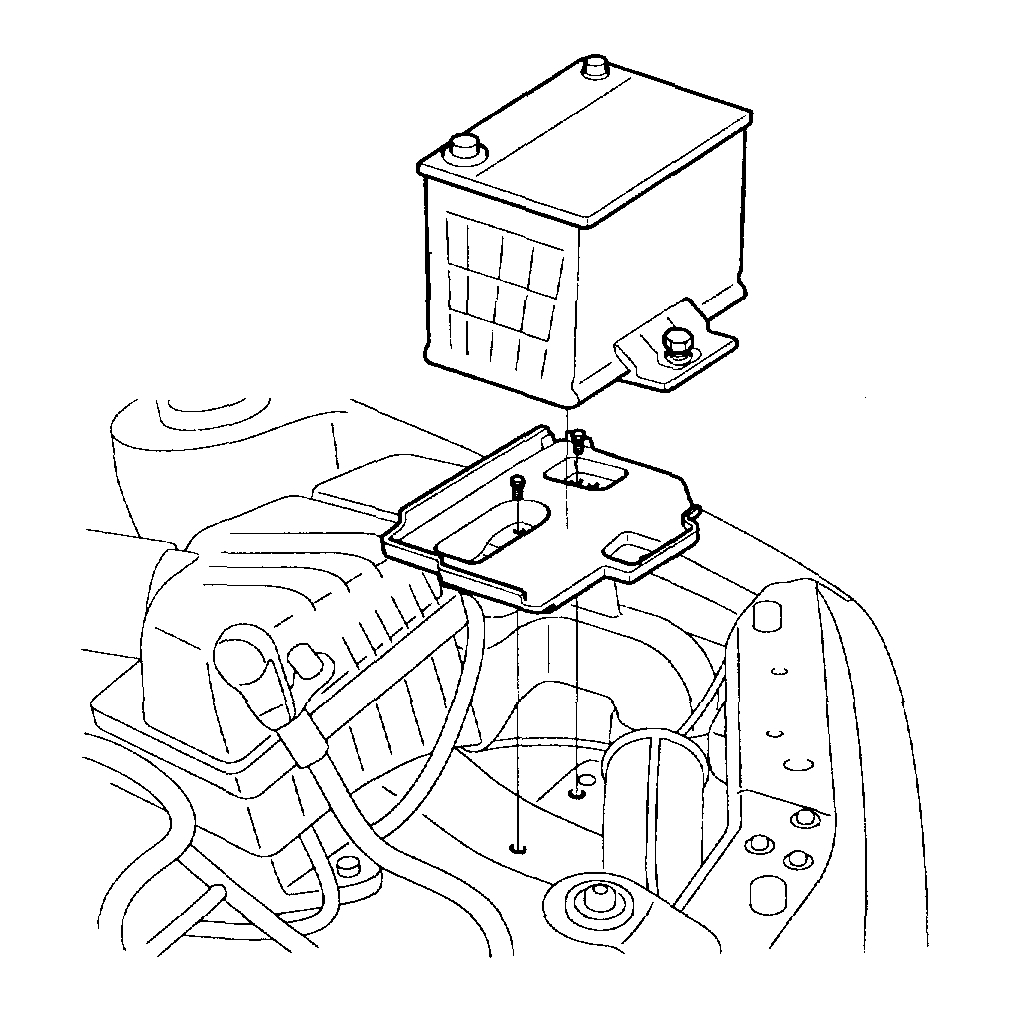
pic 1
1. Disconnect the negative terminal from the battery.
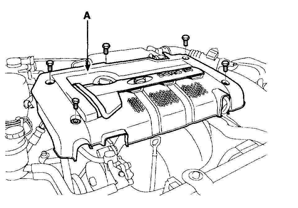
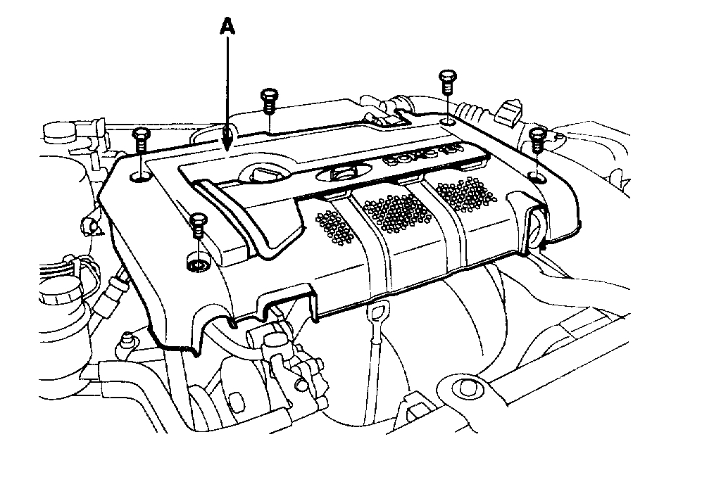
pic 2
2. Remove the engine cover(A).
3. Drain the engine coolant. Remove the radiator cap to speed draining.
4. Remove the intake air hose and air cleaner assembly
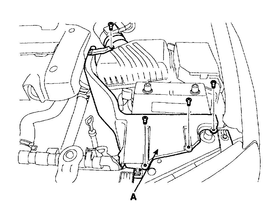
pic 3
1. Remove the heat shield (A).
2. Disconnect the AFS connector.
3. Disconnect the breather hose from air cleaner hose.
4. Remove the intake air hose and air cleaner assembly
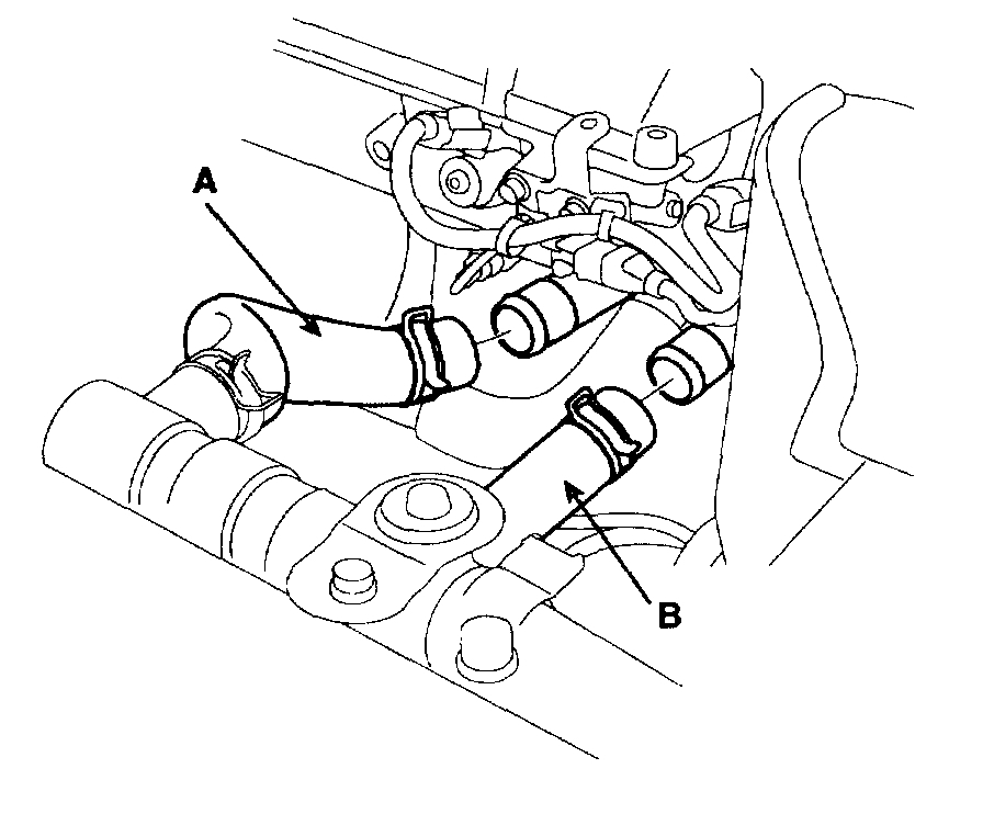
pic 4
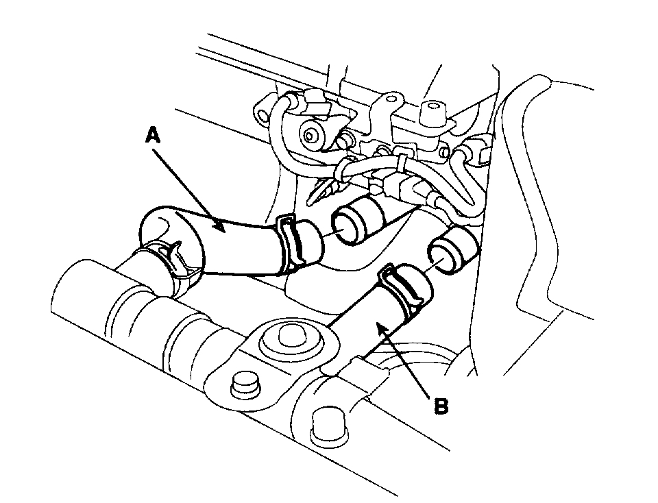
5. Remove the upper radiator hose (A) and lower radiator hose (B).
pic 5
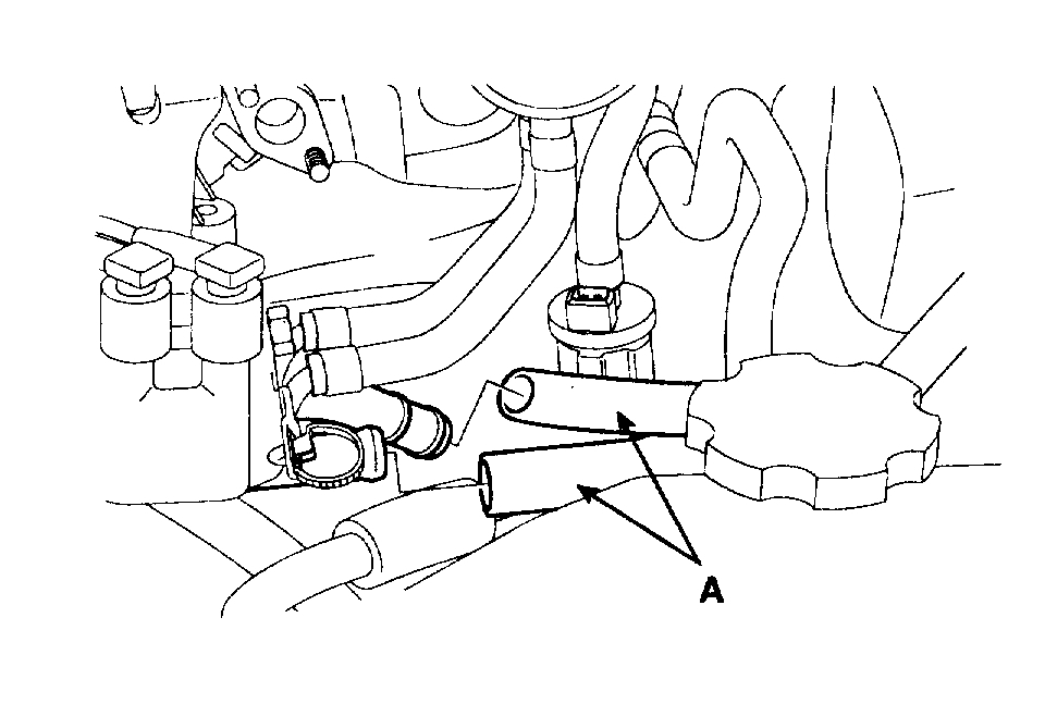
6. Remove the heater hoses (A).
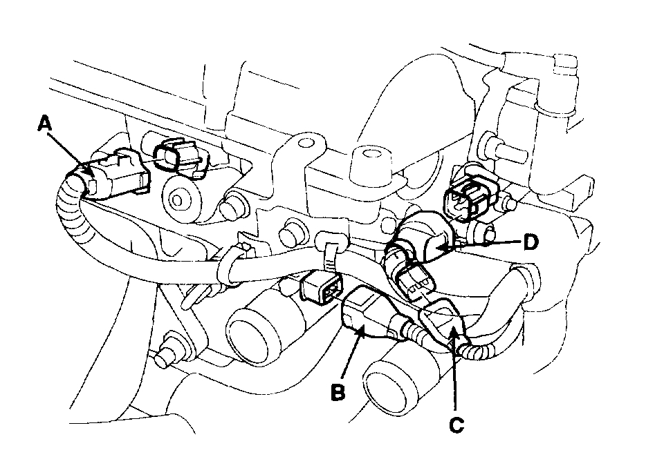
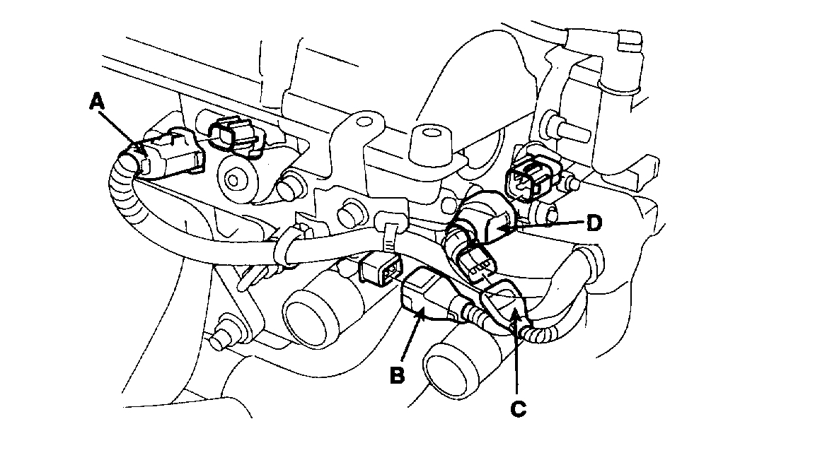
7. Remove the engine wire harness connectors and wire harness clamps from the cylinder head and the intake manifold.
1. Oil control Valve (OCV) connector (A).
2. Oil temperature sensor connector (B).
3. Engine Coolant Temperature (ECT) sensor connector (C).
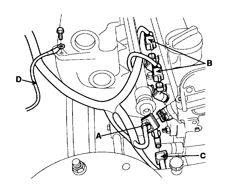
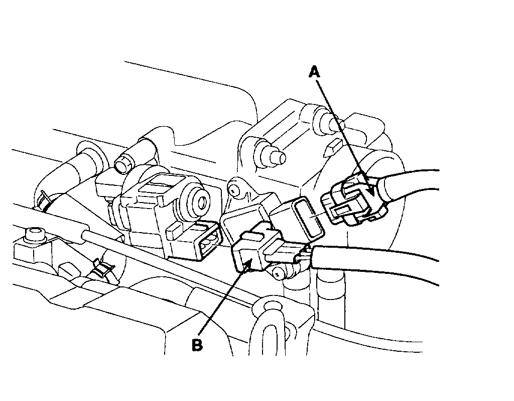
pic 6
4. Ignition coil connector (D).
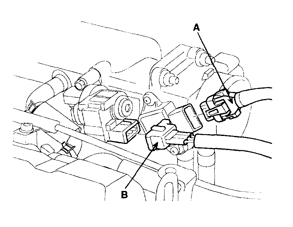
5. Throttle Position Sensor (TPS) connector (A).
pic 7
6. Idle Speed Actuator (ISA) connector (B).
7. Camshaft Position Sensor (CMP) connector (A).
8. Four fuel injector connectors (B).
9. Knock sensor connector (C).
pic 8
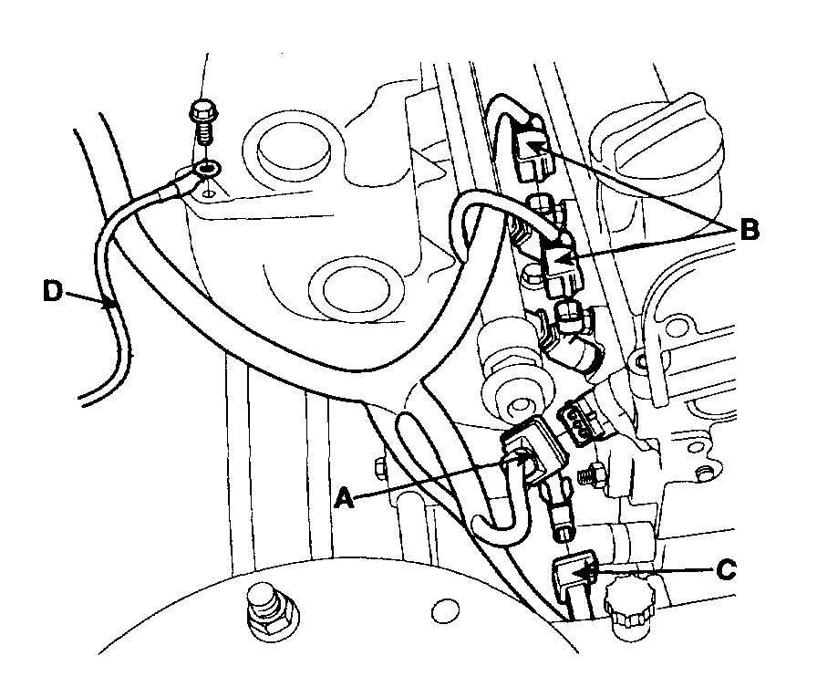
10. Disconnect ground cable (D) from the intake manifold.
pic 9
11. Front heated oxygen sensor connector (A).
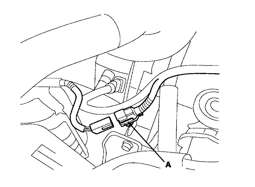
pic 10
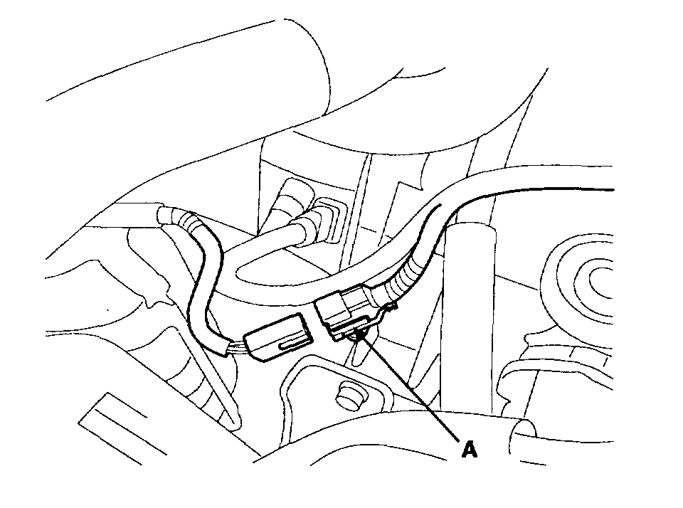
12. Purge Control Solenoid Valve (PCSV) connector (A).
pic 11
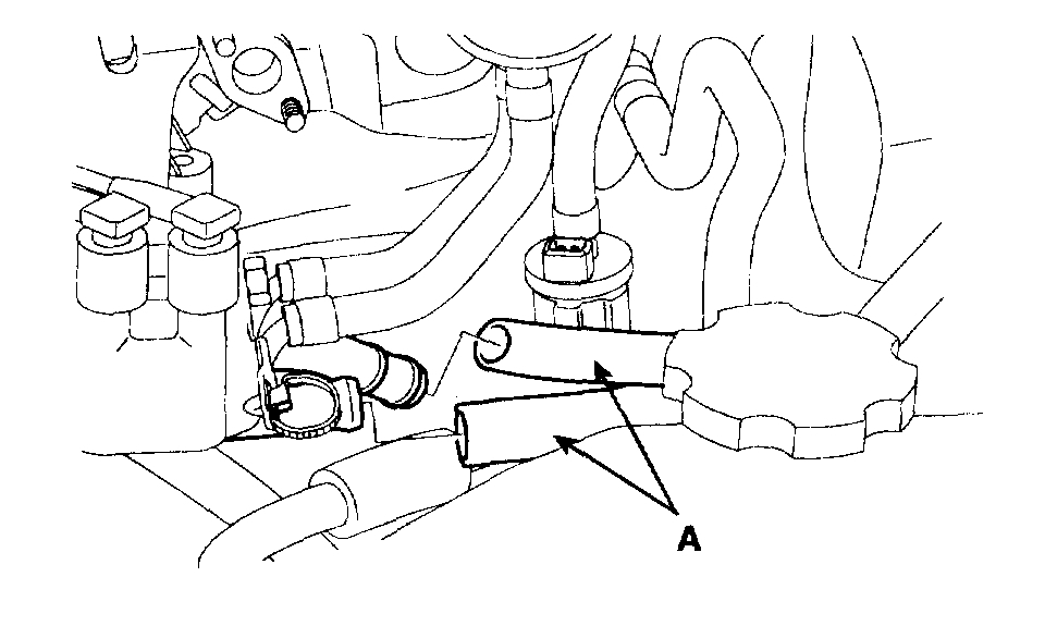
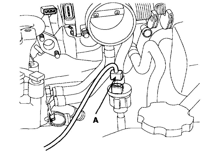
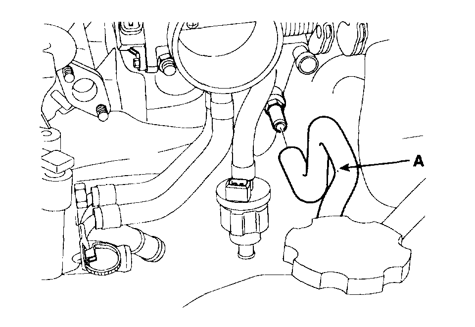
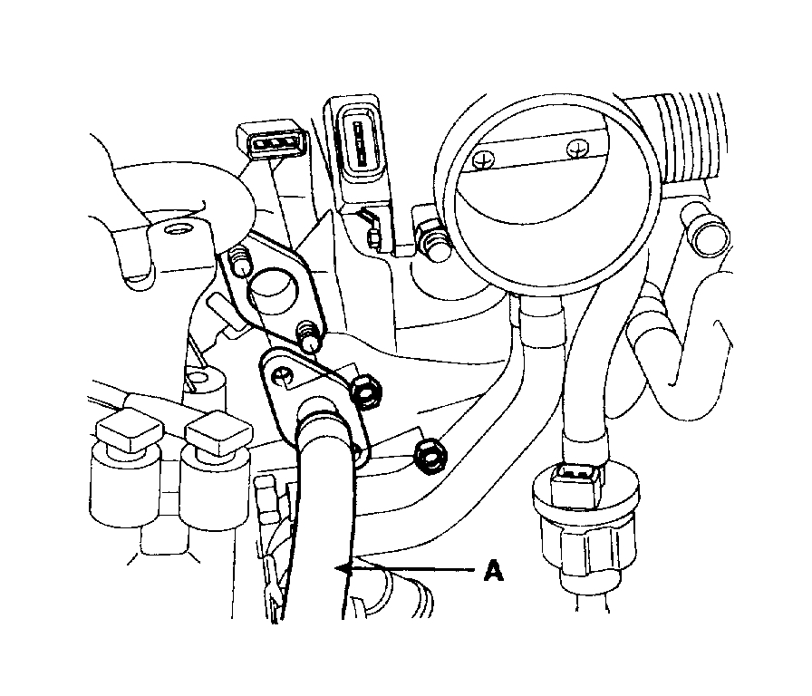
8. Remove the fuel inlet hose (A) from delivery pipe.
pic 12
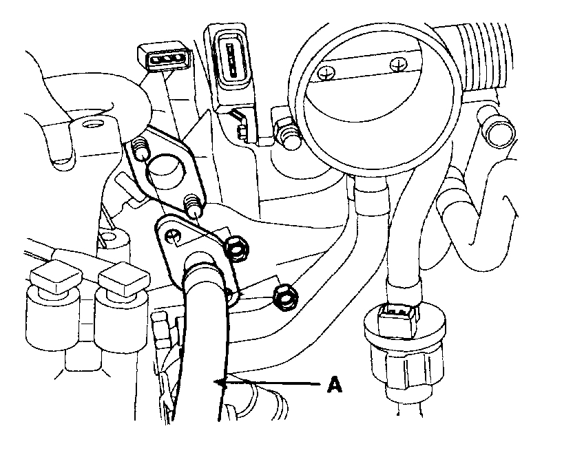
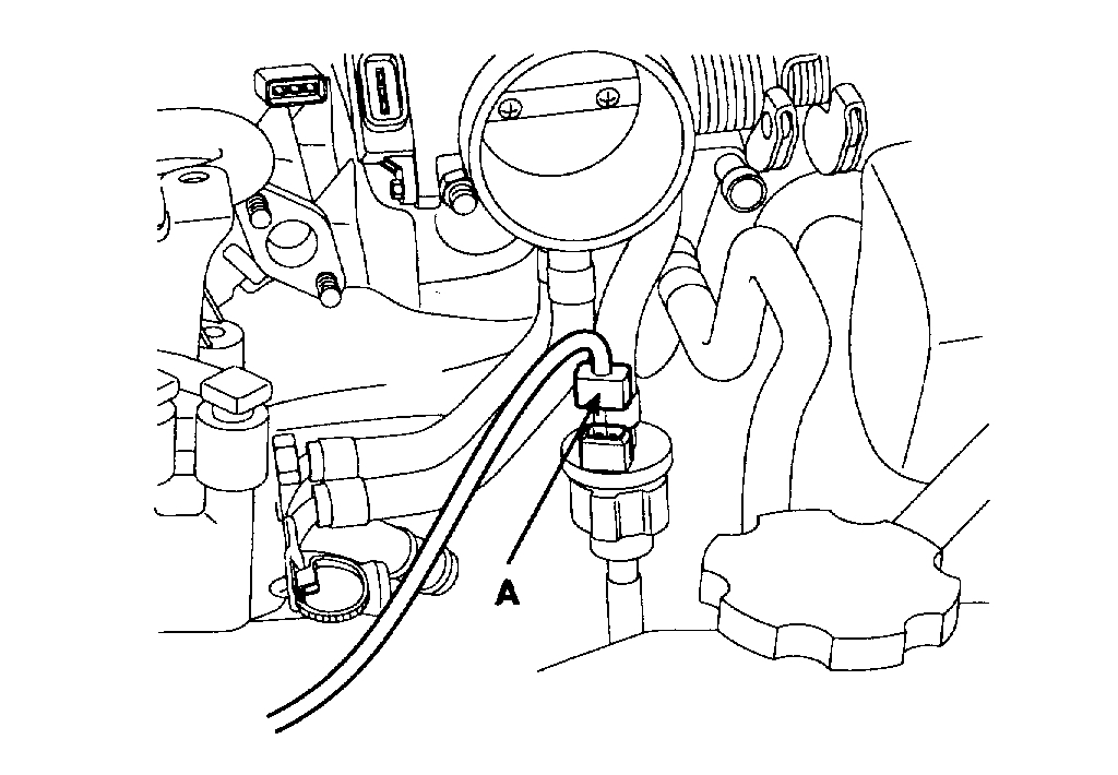
9. Remove the PCSV hose (A).
pic 13
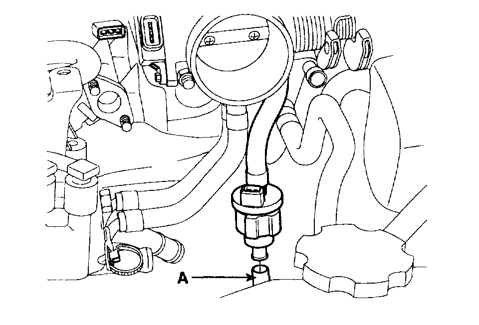
10. Remove the brake booster vacuum hose (A).
11. Remove the accelerator cable by loosening the lock nut, then slip the cable end out of the throttle linkage.
12. Remove the power steering pump.
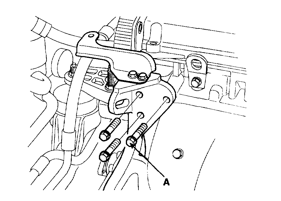
pic 14
13. Remove the power steering pump bracket bolts (A).
14. Remove the spark plug cable.
15. Remove the PCV hose.
16. Remove the cylinder head cover.
17. Remove the timing belt.
18. Remove the exhaust manifold.
19. Remove the intake manifold.
20. Remove the camshaft sprocket.
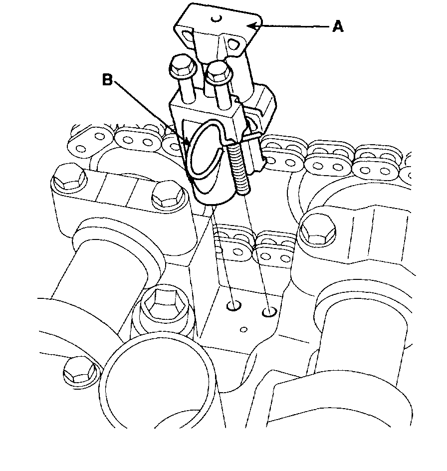
pic 15
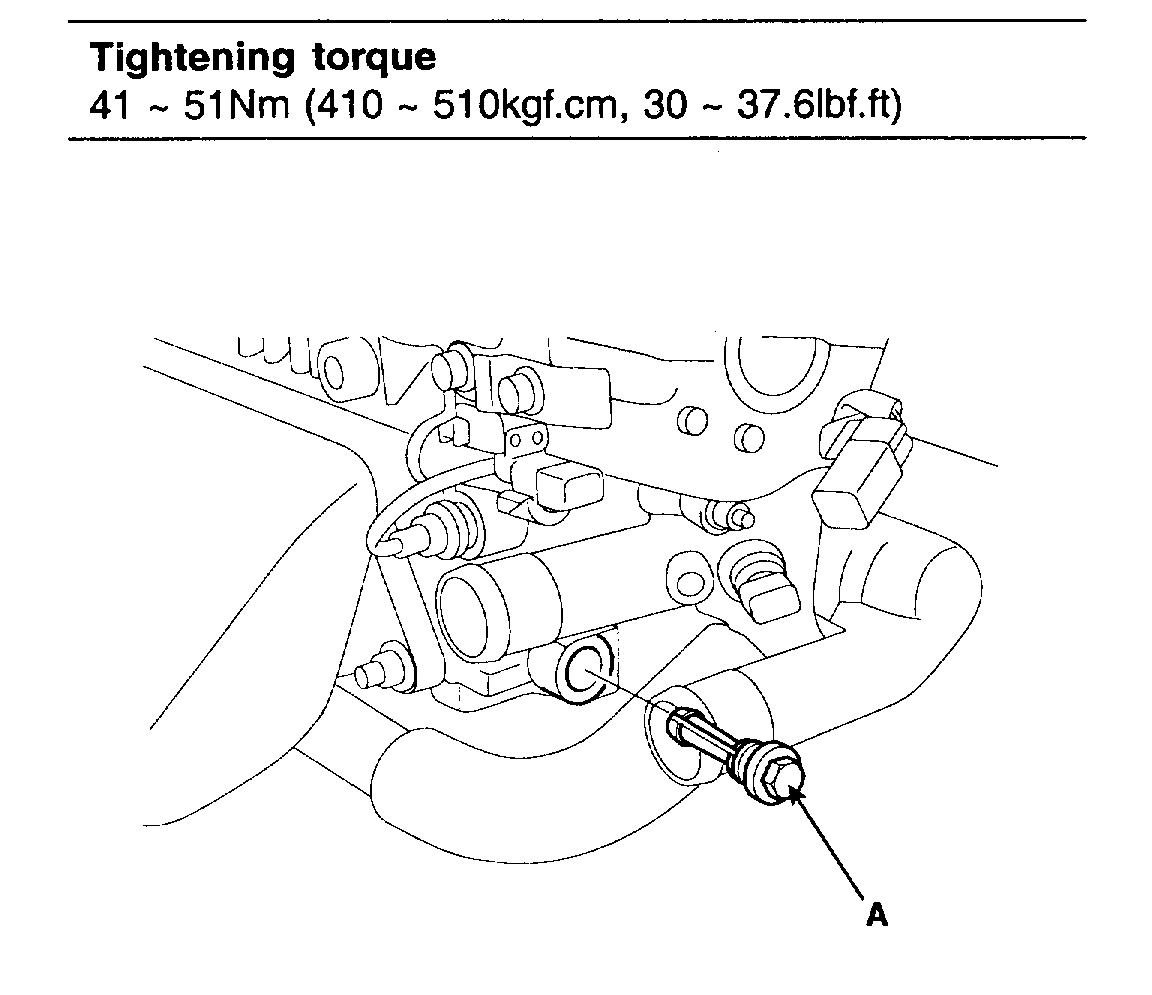
21. Remove the timing chain auto tensioner (A).
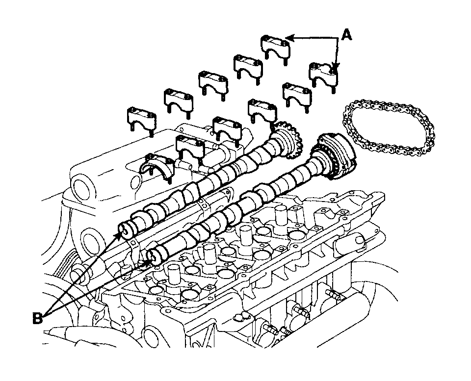
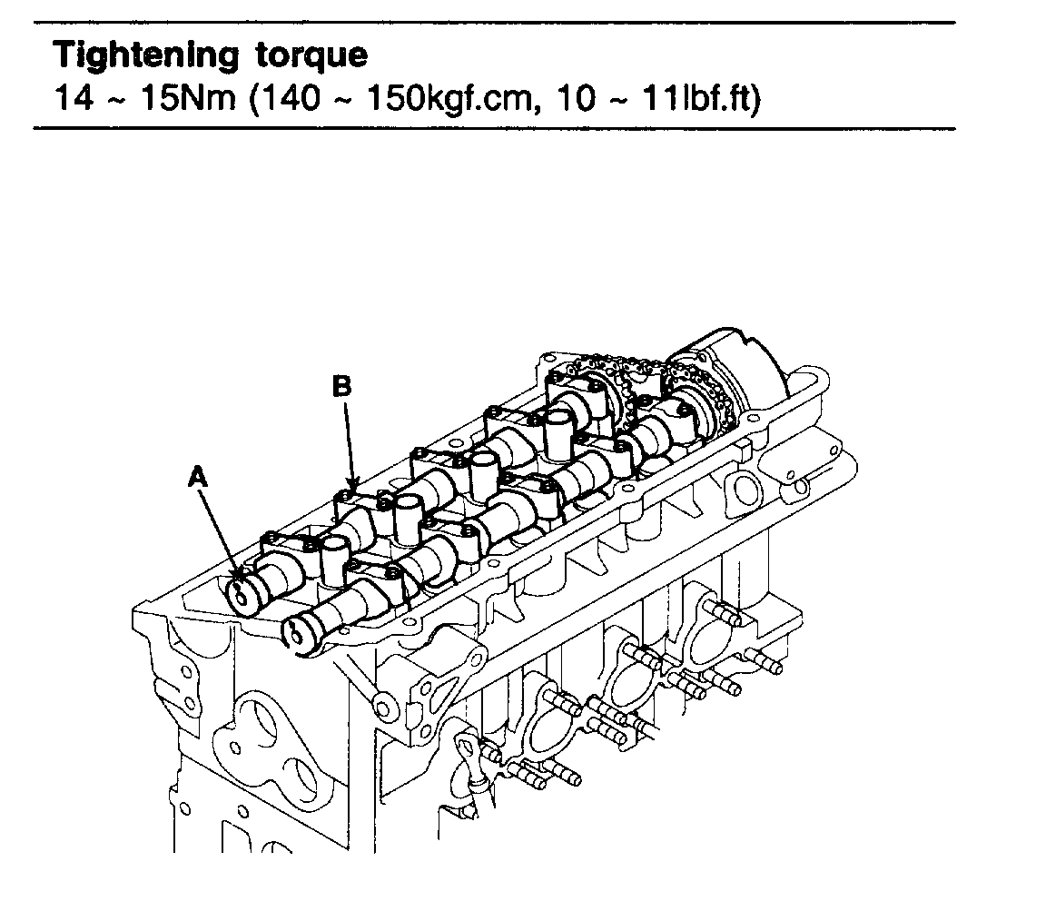
pic 16
22. Remove the camshaft bearing caps (A) and camshafts (B).
pic 17
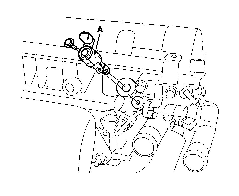
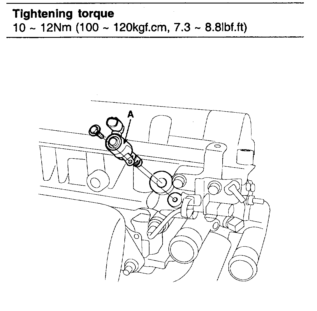
23. Remove the OCV (oil control valve) (A).
pic 18
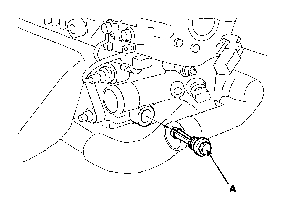
24. Remove the OCV (oil control valve) filter (A).
pic 19
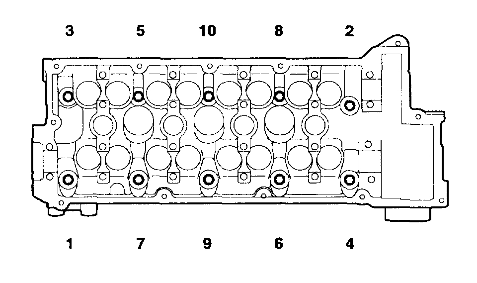
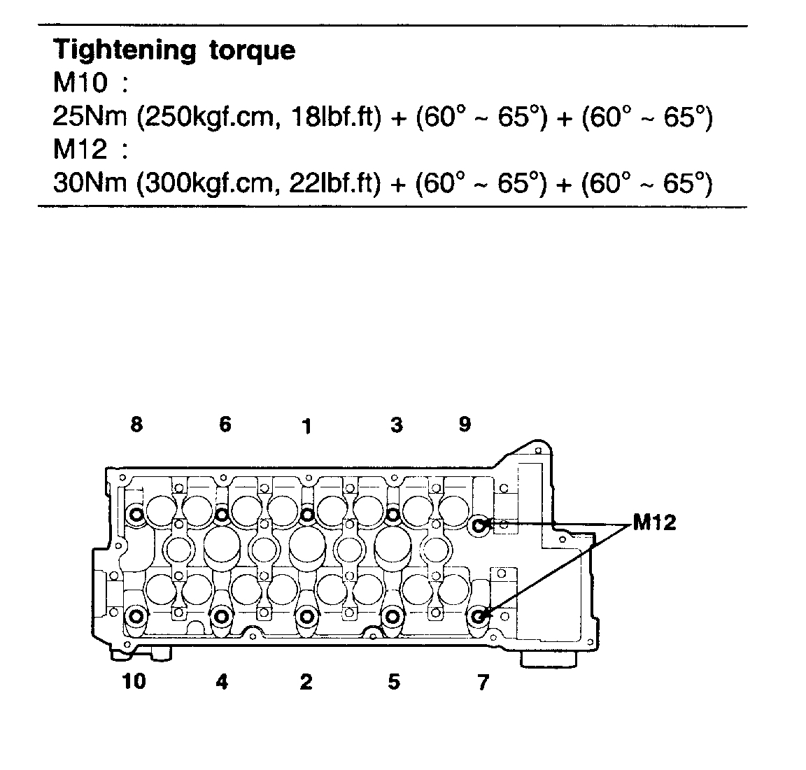
25. Remove the cylinder head bolts, then remove the cylinder head.
1. Using 8 mm and 10 mm hexagon wrench, uniformly loosen and remove the 10 cylinder head bolts, in several passes, in the sequence shown. Remove the 10 cylinder head bolts and plate washers.
CAUTION: Head warpage or cracking could result from removing bolts in an incorrect order.
2. Lift the cylinder head from the dowels on the cylinder block and replace the cylinder head on wooden blocks on a bench.
CAUTION: Be careful not to damage the contact surfaces of the cylinder head and cylinder block.
_________________________________________
Replace
2006 Hyundai Elantra L4-2.0L
Installation
Vehicle Engine, Cooling and Exhaust Engine Service and Repair Procedures Overhaul Cylinder Head Assembly Installation
INSTALLATION
CYLINDER HEAD ASSEMBLY
INSTALLATION
NOTE:
Thoroughly clean all parts to be assembled.
Always use a new head and manifold gasket.
The cylinder head gasket is a metal gasket. Take care not to bend it.
Rotate the crankshaft, set the No. 1 piston at TDC.
pic 20
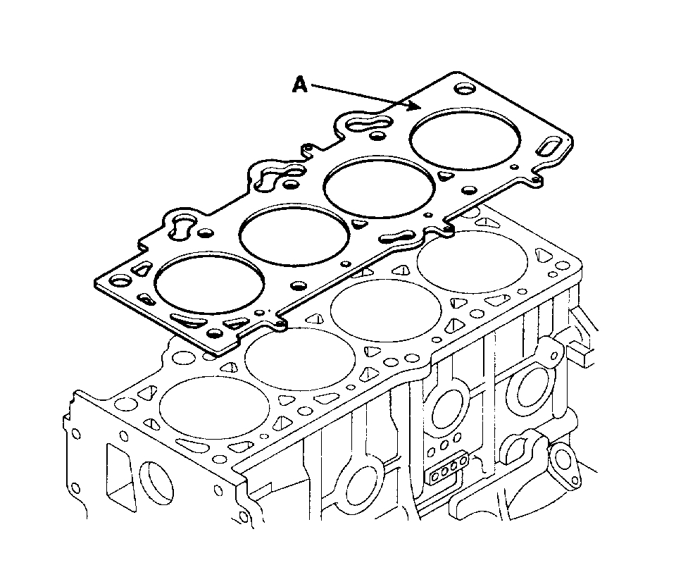
1. Install the cylinder head gasket (A) on the cylinder block.
NOTE: Be careful of the installation direction.
2. Place the cylinder head quietly in order not to damage the gasket with the bottom part of the end.
3. Install cylinder head bolts.
1. Apply a light coat if engine oil on the threads and under the heads of the cylinder head bolts.
pic 21
2. Using 8 mm and 10 mm hexagon wrench, install and tighten the 10 cylinder head bolts and plate washers, in several passes, in the sequence shown.
pic 22
4. Install OCV filter (A).
NOTE: Always use a new OCV filter gasket. Keep clean the OCV Meter.
pic 23
5. Install OCV (A)
CAUTION: Do not reuse the OCV when dropped. Keep clean the OCV Do not hold the OCV sleeve during servicing. When the OCV is installed on the engine, do not move the engine with holding the OCV yoke.
6. Install the camshafts.
pic 24
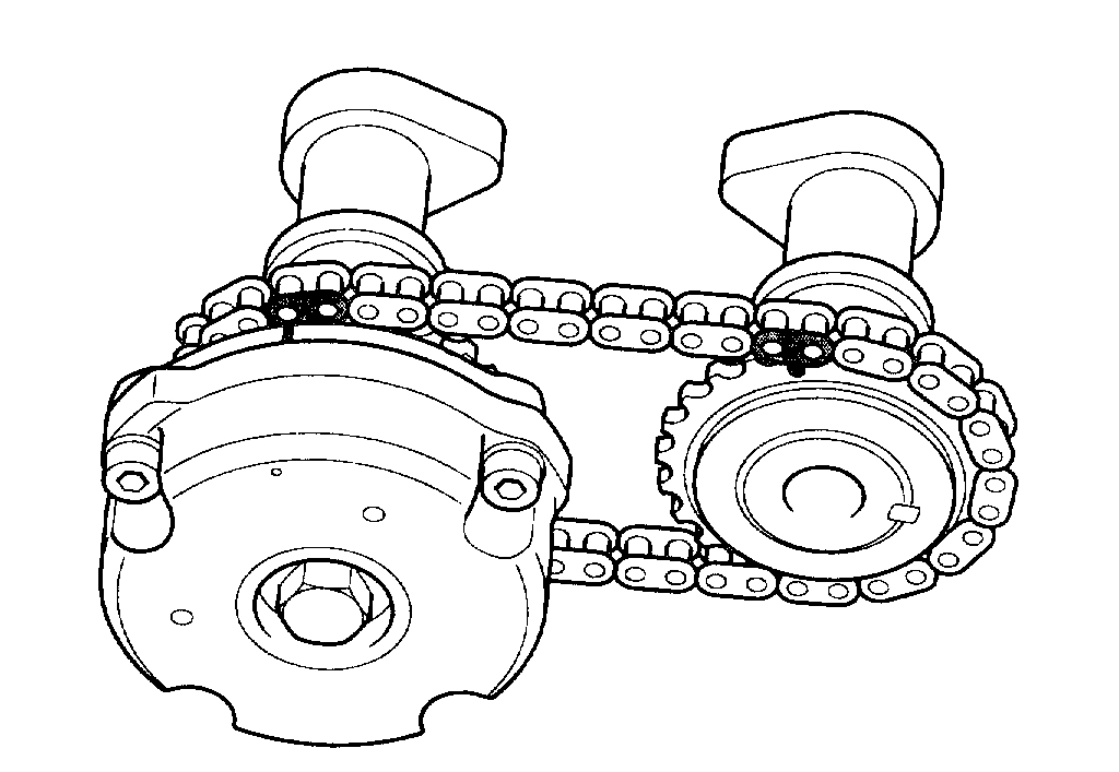
1. Align the camshaft timing chain with the intake timing chain sprocket and exhaust timing chain sprocket as shown.
pic 25
2. Install the camshafts (A) and bearing caps (B).
pic 26
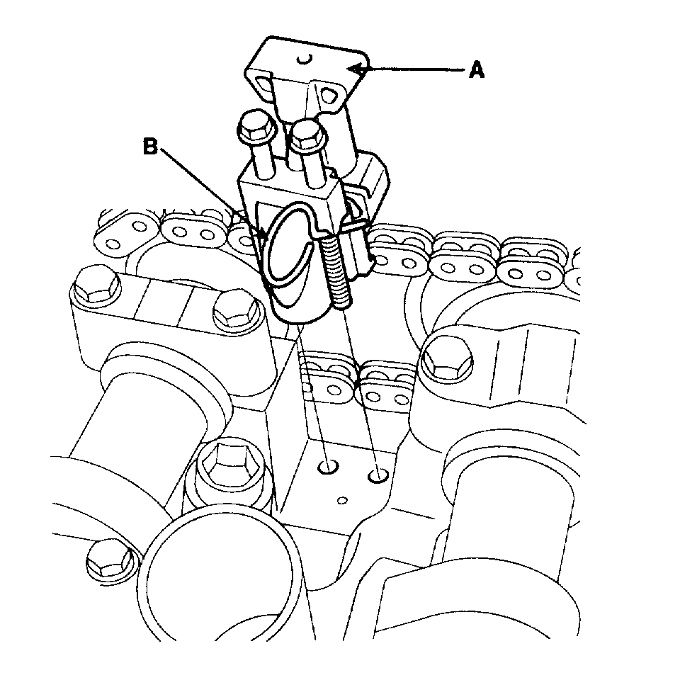
3. Install the timing chain auto tensioner (A).
4. Remove the auto tensioner stopper pin (B).
7. Check and adjust valve clearance.
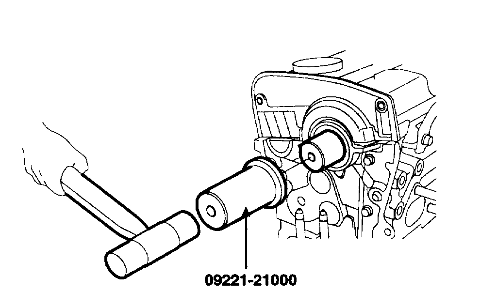
pic 27
8. Using the SST (09221-21000), install the camshaft bearing oil seal.
9. Install the camshaft sprocket.
10. Install the timing belt.
11. Install the cylinder head cover.
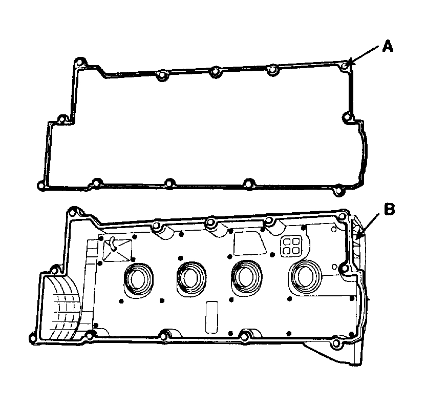
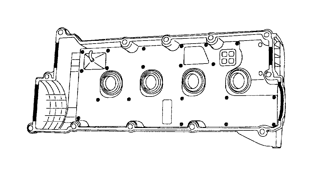
pic 28
1. Install the cylinder head cover gasket (A) in the groove of the cylinder head cover (B).
NOTE:
Before installing the head cover gasket, thoroughly clean the head cover gasket and the groove.
When installing, make sure the head cover gasket is seated securely in the corners of the recesses with no gap.
pic 29
2. Apply liquid gasket to the head cover gasket at the corners of the recess.
NOTE: Use liquid gasket, Loctite No. 5999. Check that the mating surfaces are clean and dry before applying liquid gasket After assembly, wait at least 30 minutes before filling the engine with oil.
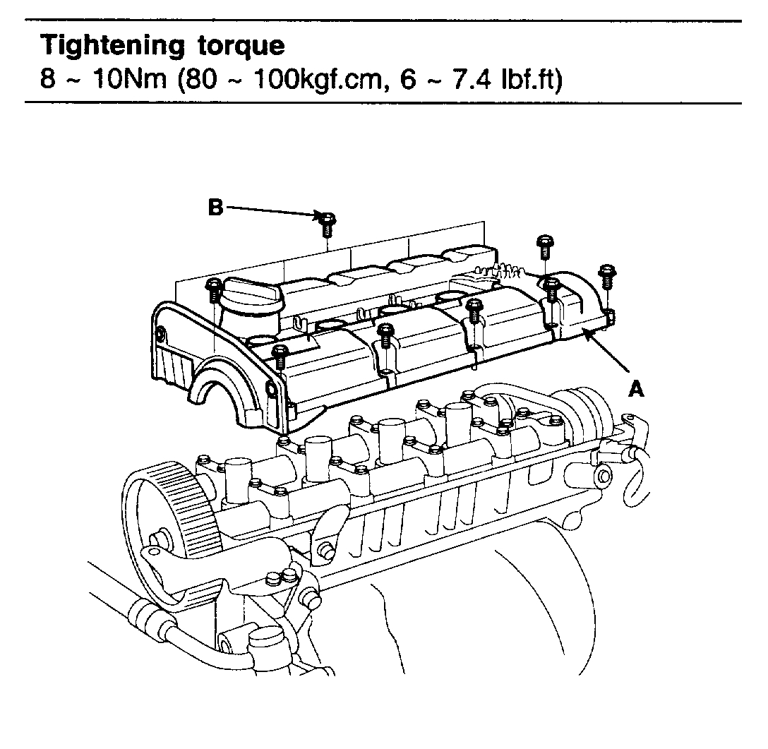
pic 30
3. Install the cylinder head cover (A) with the 12 bolts (B). Uniformly tighten the bolts in several passes.
12. Install the intake manifold.
13. Install the exhaust manifold.
14. Install the PCV.
15. Install the spark plug cable.
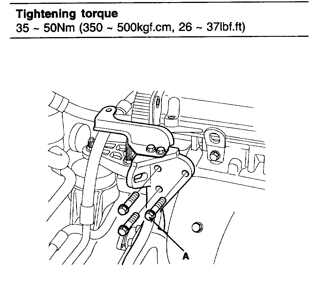
pic 31
16. Install the power steering pump bracket bolts (A).
17. Install the power steering pump.
18. Install the accelerator cable.
19. Install the bake booster hose.
pic 32
20. Install the PCSV hose (A).
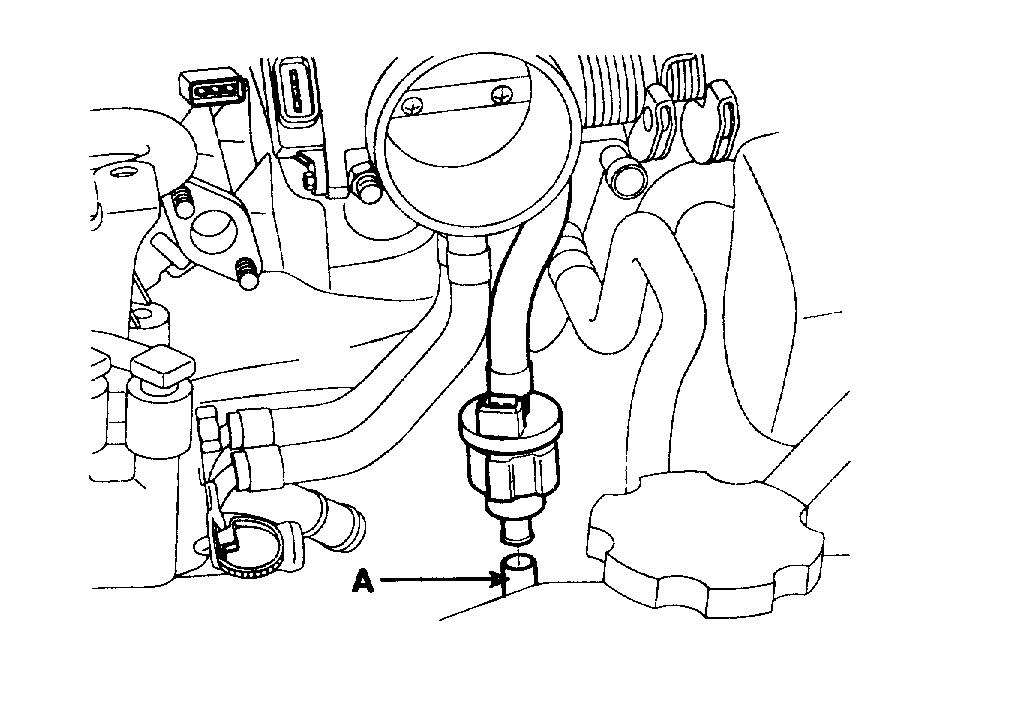
pic 33
21. Install the fuel inlet hose (A).
22. Install the engine wire harness connectors and wire harness clamps to the cylinder head and the intake manifold.
pic 34
1. PCSV connector (A).
pic 35
2. Front heated oxygen sensor connector (A).
3. Connect the ground cable to the intake manifold (D).
4. Knock sensor connector (C).
5. Four fuel injector connectors (B).
pic 36
6. CMP connector (A).
7. ISA connector (B).
pic 37
8. TIPS connector (A).
9. Ignition coil connector (D).
10. ECT sensor connector (C).
11. Oil temperature sensor connector (B).
pic 38
12. OCV connector (A).
pic 39
23. Install the heater hoses (A).
pic 40
24. Install the upper radiator hose (A) and lower radiator hose (B).
25. Install the intake air hose and air cleaner assembly.
pic 41
26. Install the engine cover (A).
27. Connect the negative terminal to the battery.
28. Fill with engine coolant.
29. Start the engine and check for leaks.
30. Recheck engine coolant level and oil level.
_________________________
I hope this helps. Please let me know if you have other questions or need help.
Take care,
Joe
Images (Click to make bigger)
Wednesday, April 1st, 2020 AT 7:49 PM