My my my. Chrysler has always led the way with innovations that had positive impacts on car owners. One of them was the "AC Generator" they developed and first used on 1960 models. They copyrighted the term "alternator". In my opinion, they have always had the best designs that were by far, the easiest to diagnose and repair. So you can imagine how disappointed I am that they had to go and change it.
I used to be able to tell a lot about the charging system by taking one voltage reading on terminal 1 on the alternator or anywhere along that wire. I don't know what problem they found a solution for but with the old system you could tell instantly if the alternator's internal brushes were good. Now I need to take multiple measurements. The problem is I have to perform a continuity test from terminal 1 to ground when the ignition switch is off, and when the field winding is not spinning it is real common to find a bad connection on those brushes even when they're perfectly fine. They resume making good contact when the field winding is in motion.
Sorry for whining like a little school girl, but they could have left a good system alone. I suppose some engineer needed to justify his need for being there. I wasn't happy in the late '80s when they built the regulator into the Engine Computer because replacing it meant buying a multi-hundred dollar computer instead of a fifteen dollar box, but as it turns out, that regulator circuit has been extremely reliable and they very seldom fail. The advantage to this system is the regulator "knows" everything the computer knows. Chrysler was also first with the electronic voltage regulator in 1970, and it could vary battery charging rate according to outside temperature. Charging a battery after all is a chemical process, and at higher temperatures we need to lower charging voltage a little to prevent boiling the water out of the acid.
With the regulator inside the Engine Computer, charging voltage can be varied according to air temperature with a sensor that sits right next to the battery, so it looks at battery temperature, and other sensor readings. It can anticipate additional loads about to be turned on by the computer, like the AC compressor. The computer can also command the alternator to stop completely. It can take over five horsepower to run it, and that may be just the five horsepower you need when passing a freight train, . . . going up a steep hill, . . . while pulling a big trailer, . . . with Ma and the kids in back! The computer sees wide-open-throttle and other conditions that could benefit from a momentary loss of the alternator's drag on the engine.
The point is, it's a very nice system and they didn't have to change anything because they aren't going to be able to make it better. The other thing they changed is where the voltage regulator senses system voltage. That used to come off the automatic shutdown (ASD) relay that also powered the ignition coils, injectors, and fuel pump. I can probably live with them changing that to terminal 2 on the alternator since the effect is the same, but the problem is there is going to be full battery voltage or full charging voltage there depending on whether the engine is running or off. That is the same voltage you would have found on the older system except for a different reason. This is where a lot of experienced and knowledgeable mechanics are going to get confused. On the old system, that 12 volts was the current source that fed the field winding to make the electromagnetic field. On this system, it's just monitoring battery / charging voltage. There's no need to run it through the alternator.
Okay, that's enough for today's lesson. You will not be tested on this later! I don't know why they saw fit to fuse this circuit and I don't know why they ran it through the alternator. On the Ford design, they have the same wire, also with 12 volts all the time, and they also use other connections like the starter on your car as convenient tie points, but they don't go through the alternator and another potential bad connection on that terminal.
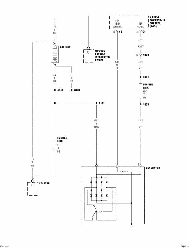
Anyway, . . . to address your question, finally, yes you can tell the gauge of the wire by the designation on Chrysler's wiring diagrams. If I'm reading this one correctly, it looks like "
A833 22WT". If that's right, "A" circuits originate at the battery positive terminal and almost always have 12 volts on them as this one does. "833" is the circuit number. "22" is the gauge, and "WT" is for "white". If you ask at the parts store for a white fuse link wire, you'll get about 12" of wire of the correct gauge. You can also find these at a salvage yard. Through most of the '80s and '90s Chrysler bundled a bunch of fuse link wires and ran that bundle around the front of the left strut tower. The most common ones used were white and gray, but here and there you'll find a black, green, or orange one too.
I'm not sure what you're measuring with your meter. Most of them don't have ranges for alternating current. If they do, they can only usually measure up to two amps. That is of no use anywhere in a car. When a meter can measure AC current or AC voltage, that is only accurate at 60Hz which is house current. Alternators put out three-phase current. Professional load testers measure the resulting "ripple" voltage with no regard to frequency, (hertz) or engine speed. With one bad diode, one of the three phases will be missing and during that time voltage drops a lot. It's that difference between the lowest voltage and the highest voltage that is ripple voltage. We can't measure that with a digital meter.
I should back up a minute and start from the beginning. When testing the charging system, the only thing you can do is measure battery voltage. With the engine off, a good, fully-charged battery will read 12.6 volts. A good, fully-discharged battery will read close to 12.2 volts. Next, with the engine running, you must find between 13.75 and 14.75 volts. If you do, that only proves the system is working sufficiently for the next tests. Those require that professional load tester. An alternator is physically incapable of being forced to generate more than its design current rating. One failed diode will cut that to exactly one third. One of the common alternators for your car is rated at 120 amps. Under full load during the test, it is going to develop either 120 amps if it's good or close to 40 amps if it has a bad diode. Therefore, a bad diode will show up as only one third of normal maximum current, and high ripple voltage. There's no other way to test for a bad diode other than to disassemble the alternator, disconnect the diodes so you're testing only one at a time, then test them with the "diode test" function on your meter or with the lowest ohmmeter scale. Even that can't be done on many alternators because three diodes are sandwiched into an assembly and they get wrecked by pulling them apart. GM went even further and put all six into a sealed block with puny little tabs that break off when you try to take them apart.
My last concern is why that fuse link burned open. I forgot to mention that you test them by pulling on them. If they act like a wire, they're good. If they act like a rubber band, they're burned open. You replace them by cutting off the ends of the wires they're spliced to, splice the new link in, solder the splices, then seal them with heat-shrink tubing with hot-melt glue inside. Never use electrical tape on a car. It will unravel into a gooey mess on a hot day.
Before you do this, I would suggest using small jumper wires to connect a regular fuse in place of this link. If it doesn't blow, start the engine and see if the charging system is working by measuring battery voltage. If it is, install the new link. If the fuse blows, I'll have to think on this some more. Use a large fuse. If there's a problem, it's going to blow and protect the wiring. Fuse link wires are used because they take some time to burn open. That delay is needed to accommodate the normal surges some things draw when they're starting up. A regular fuse will blow too quickly.
Mar 14, 2015 at 11:37 PM