I do not see any code info for U0014. U0001 is for the PCM losing communication through the C bus line. I would recommend you take it in to a shop or the dealership for proper diagnostic. Any module on that circuit that goes down could take down the rest of the modules. Lets do a CAN scan which is the future of automotive repair you can get a CAN scanner from Amazon for about $50.00 here is a video to show you how.
https://youtu.be/u-4syLc-ifQ Here is a description oft he CAN Bus system.
COMMUNICATION
DESCRIPTION
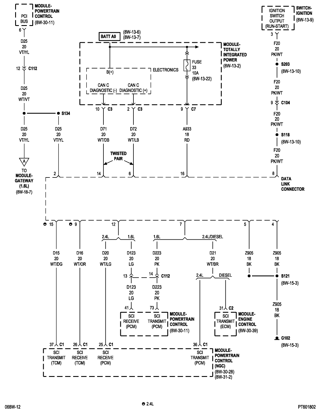
The primary on-board communication network between microprocessor-based electronic control modules in this model is the Controller Area Network (CAN) data bus system. However, on models with an optional 1.6 liter engine the Powertrain Control Module (PCM) uses the DaimlerChrysler Programmable Communication Interface (PCI) data bus system in combination with the CAN bus to form a hybrid bus system. A data bus network minimizes redundant wiring connections; and, at the same time, reduces wire harness complexity, sensor current loads and controller hardware by allowing each sensing device to be connected to only one module (also referred to as a node). Each node reads, then broadcasts its sensor data over the bus for use by all other nodes requiring that data. Each node ignores the messages on the bus that it cannot use.
The CAN bus is a two-wire multiplex system, while the PCI bus is a single-wire multiplex system. Multiplexing is any system that enables the transmission of multiple messages over a single channel or circuit. The CAN bus is used for communication between all vehicle nodes, except on models with the 1.6 liter engine where the PCM uses the PCI bus. In addition, certain vehicles may also be equipped with a Serial Controller Interface (SCI) or a K-Line serial link bus to provide direct diagnostic access between a diagnostic scan tool connected to the industry-standard 16-way Data Link Connector (DLC) located below the driver side instrument panel and certain powertrain nodes.
There are actually three separate CAN bus systems used in the vehicle. They are designated: the CAN-B, the CAN-C and the Diagnostic CAN-C. The CAN-B and CAN-C systems provide on-board communication between all nodes in the vehicle. The CAN-C is the faster of the two systems providing near real-time communication (500 Kbps ), but is less fault tolerant than the CAN-B system. The CAN-C is used exclusively for communications between critical powertrain and chassis nodes. The slower (83.3 Kbps ), but more fault tolerant CAN-B system is used for communications between body and interior nodes. The CAN-B fault tolerance comes from its ability to revert to a single wire communication mode if there is a fault in the bus wiring.
The added speed of the CAN data bus is many times faster than previous data bus systems. This added speed facilitates the addition of more electronic control modules or nodes and the incorporation of many new electrical and electronic features in the vehicle. The Diagnostic CAN-C bus is also capable of 500 Kbps communication, and is sometimes informally referred to as the CAN-D system to differentiate it from the other high speed CAN-C bus. The Diagnostic CAN-C is used exclusively for the transmission of diagnostic information between the Totally Integrated Power Module/Central GateWay (TIPM or TIPMCGW) and a diagnostic scan tool connected to the DLC.
NOTE: The 1.6L gateway is only on vehicles being shipped to Europe. There is no domestic application of the 1.6L. The TIPM is still the main CAN gateway, the additional gate way goes from CAN C to J-1850 for the 1.6L powertrain controller.
All models have a central CAN gateway or hub module integral to the TIPM that is connected to all three CAN buses. The TIPM is located in the engine compartment near the battery. This gateway physically and electrically isolates the CAN buses from each other and coordinates the bi-directional transfer of messages between them. On models with the 1.6 liter engine a separate, dedicated gateway module secured to the floor under the driver side front seat in the passenger compartment coordinates the bi-directional transfer of messages between the PCI bus line from the PCM and the CAN bus connected to all of the other nodes in the vehicle.
OPERATION
Either the Controller Area Network (CAN) data bus or the hybrid bus system that integrates the Programmable Communications Interface (PCI) data bus with the CAN bus allows all electronic modules or nodes connected to the bus to share information with each other. Regardless of whether a message originates from a module on the low speed PCI or CAN-B bus or on the high speed CAN-C or CAN-D bus, the message structure and layout is similar, which allows the Totally Integrated Power Module/Central GateWay (TIPM or TIPMCGW) to process and transfer messages between the buses. The TIPM also stores a Diagnostic Trouble Code (DTC) for certain bus network faults.
All modules (also referred to as nodes) transmit and receive messages over one of these buses, either the single-wire PCI bus or the two-wire CAN bus. Data exchange between nodes is achieved by serial transmission of encoded data messages. Each node can both send and receive serial data simultaneously. Bus messages are carried over the data bus in the form of Variable Pulse Width Modulated (VPWM) signals which, when the high and low voltage pulses are strung together, form a message. Each node uses arbitration to sort the message priority if two competing messages are attempting to be broadcast at the same time.
The voltage network used to transmit messages requires biasing and termination. Each module on the bus network provides its own biasing and termination. Each node terminates the bus through a terminating resistor and a terminating capacitor. There are two types of nodes on the bus. The dominant node terminates the bus through a 1 KW resistor and a 3300 pF capacitor, typically resulting in about a 3300 ohm termination resistance. However, this resistance value may vary somewhat by application. The TIPM (or TIPMCGW) is the only dominant node in this network. A non-dominant (or recessive) node terminates the bus through an 11 KW resistor and a 330 pF capacitor, typically resulting in about a 10800 ohm termination resistance.
PROGRAMMABLE COMMUNICATIONS INTERFACE DATA BUS
The PCI (or J1850) data bus communication protocol exceeds the Society of Automotive Engineers (SAE) J1850 Standard for Class B Multiplexing. The PCI data bus speed is an average 10.4 Kilobits per second (Kbps) .
The Programmable Communication Interface Multiplex system (PCI Bus) consist of a single wire. The Body Control Module (BCM) acts as a splice to connect each module and the Data Link Connector (DLC) together. Each module is wired in parallel to the data bus through its PCI chip set and uses its ground as the bus reference. The wiring is a minimum 20 gage wire.
Various modules exchange information through a communications port called the PCI Bus. The Powertrain Control Module (PCM) transmits the Malfunction Indicator Lamp (Check Engine) On/Off signal and engine RPM on the PCI Bus. The PCM receives the Air Conditioning select input, transaxle gear position inputs over the PCI Bus. The PCM also receives the air conditioning evaporator temperature signal from the PCI Bus.
The following components access or send information on the PCI Bus.
Instrument Panel
Body Control Module
Air Bag System Diagnostic Module
Full ATC Display Head (if equipped)
ABS Module
Transmission Control Module
Powertrain Control Module
Travel Module
SKIM
CONTROLLER AREA NETWORK DATA BUS
The communication protocol being used for the CAN data bus is a non-proprietary, open standard adopted from the Bosch CAN Specification 2.0 b . The CAN is the faster of the two primary buses in the hybrid bus system, with the CAN-C bus providing near real-time communication (500 Kbps ).
The CAN bus nodes are connected in parallel to the two-wire bus using a twisted pair, where the wires are wrapped around each other to provide shielding from unwanted electromagnetic induction, thus preventing interference with the relatively low voltage signals being carried through them. The twisted pairs have between 33 and 50 twists per meter . While the CAN bus is operating (active), one of the bus wires will carry a higher voltage and is referred to as the CAN High or CAN bus (+) wire, while the other bus wire will carry a lower voltage and is referred to as the CAN Low or CAN bus (-) wire. Refer to the CAN Bus Voltages table.
In order to minimize the potential effects of Ignition-Off Draw (IOD), the CAN-B network employs a sleep strategy. However, a network sleep strategy should not be confused with the sleep strategy of the individual nodes on that network, as they may differ. For example: The CAN-C bus network is awake only when the ignition switch is in the On or Start positions; however, the TIPM, which is on the CAN-C bus, may still be awake with the ignition switch in the Accessory or Unlock positions. The integrated circuitry of an individual node may be capable of processing certain sensor inputs and outputs without the need to utilize network resources.
The CAN-B bus network remains active until all nodes on that network are ready for sleep. This is determined by the network using tokens in a manner similar to polling. When the last node that is active on the network is ready for sleep, and it has already received a token indicating that all other nodes on the bus are ready for sleep, it broadcasts a "bus sleep acknowledgment" message that causes the network to sleep. Once the CAN-B bus network is asleep, any node on the bus can awaken it by transmitting a message on the network. The TIPM will keep either the CAN-B or the CAN-C bus awake for a timed interval after it receives a diagnostic message for that bus over the Diagnostic CAN-C bus.
In the CAN system, available options are configured into the TIPM at the assembly plant, but additional options can be added in the field using the diagnostic scan tool. The configuration settings are stored in non-volatile memory. The TIPM also has two 64-bit registers, which track each of the "as-built" and "currently responding" nodes on the CAN-B and CAN-C buses. The TIPM stores a Diagnostic Trouble Code (DTC) in one of two caches for any detected active or stored faults in the order in which they occur. One cache stores powertrain (P-Code), chassis (C-Code) and body (B-Code) DTCs, while the second cache is dedicated to storing network (U-Code) DTCs.
If there are intermittent or active faults in the CAN network, a diagnostic scan tool connected to the Diagnostic CAN-C bus through the 16-way Data Link Connector (DLC) may only be able to communicate with the TIPM. To aid in CAN network diagnosis, the TIPM will provide CAN-B and CAN-C network status information to the scan tool using certain diagnostic signals. In addition, the transceiver in each node on the CAN-C bus will identify a "bus off hardware failure," while the transceiver in each node on the CAN-B bus will identify a "general bus hardware failure." The transceivers for some CAN-B nodes will also identify certain failures for both CAN-B bus signal wires.
Oct 3, 2016 at 1:05 PM