Hello,
I have found some information on how to replace the timing chain and set up the camshaft acuators. Here is what I have found. Make sure you check out the diagrams at the bottom of this post!
Special tools, testers and auxiliary items required:
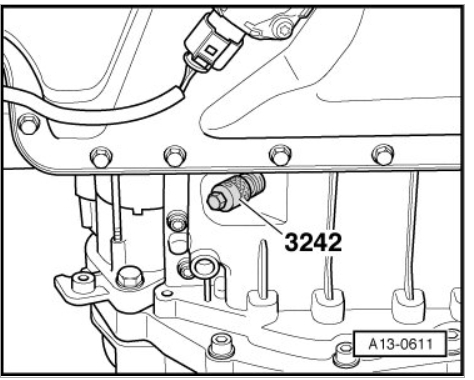
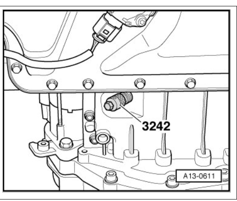
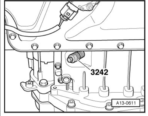
¤ Crankshaft Holder (3242)
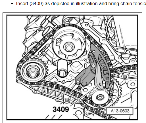
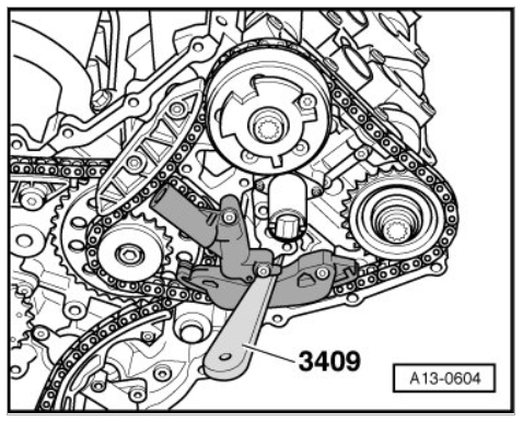
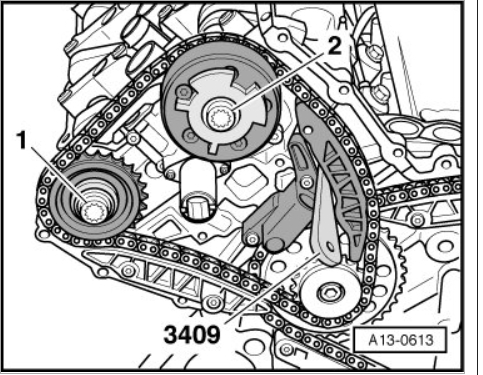
¤ Trim Removal Wedge (3409) (2x)
¤ Old Oil Collecting and Extracting Device (V.A.G 1782)
¤ Multipoint Socket (T10035)
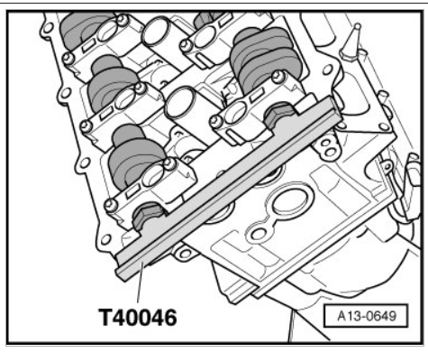
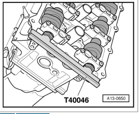
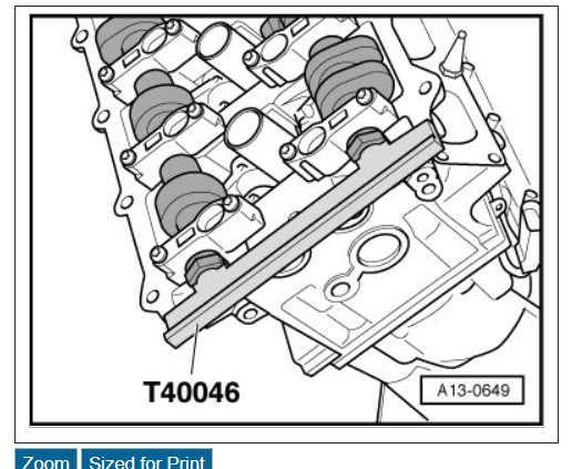
¤ Camshaft Locator (T40046) (quantity: 2)
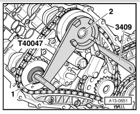
¤ Setting Gauge (T40047)
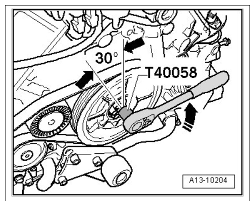
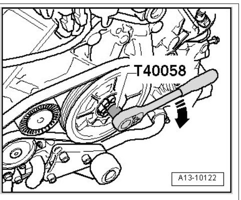
¤ Socket (T40058)
¤ Two 3.3 mm drill bits
Procedure
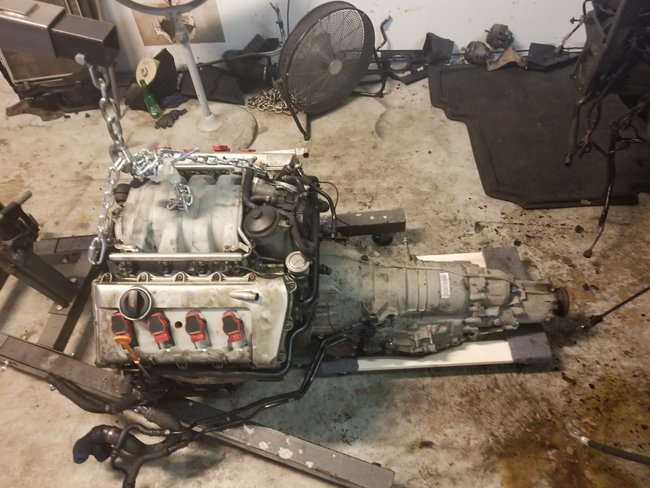
Remove engine. Refer to => [ Engine, Removing ] See: Service and RepairRemoval and ReplacementEngine, Removing.
Separate engine/transmission. Refer to => [ Engine and Transmission, Separating ] See: Service and RepairRemoval and ReplacementEngine and Transmission, Separating.
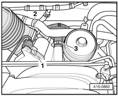
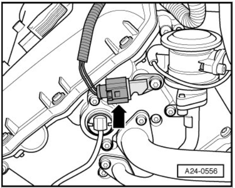
Disconnect electrical connection - 1 - at throttle valve control module (J338).
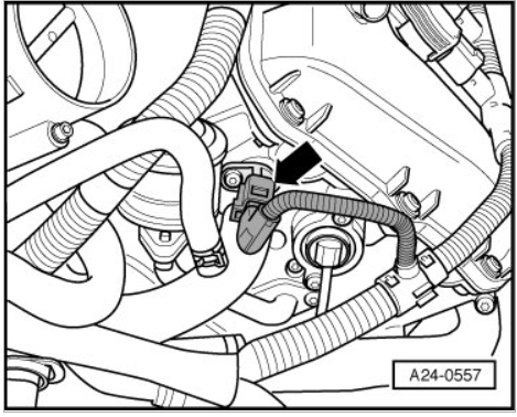
Disconnect crankcase ventilation hose - 3 - at the intake pipe.
¤ Ignore - 2 -.
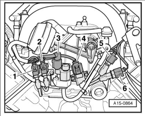
Remove electrical harness connectors - 1, 2, 5 and 6 -, toward the front from brackets on intake pipe.
Disconnect the connectors - 3 and 4 -.
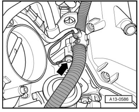
Disconnect vacuum hose - arrow - at T-piece.
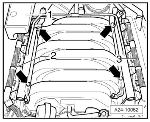
Pull off the connector strips - 2 and 3 - at the 8 fuel injectors.
Remove bolts - arrows - from fuel rails.
Pull fuel rail with injectors upward uniformly from intake manifold and set aside in the engine compartment on a clean cloth.
¤ Carefully protect the removed fuel injectors from contamination.
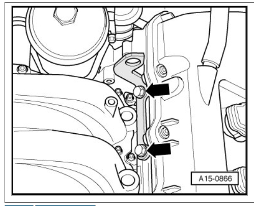
Remove the left rear engine lifting eye - arrows -.
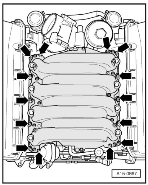
Remove the intake manifold bolts - arrows - and remove manifold.
¤ Plug the intake ports of the cylinder head with clean rags.
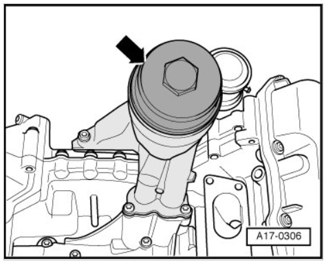
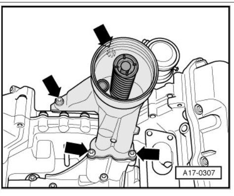
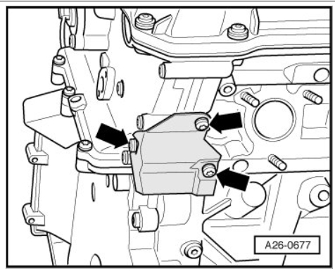
Remove cover - arrow - for oil filter housing.
Remove oil filter element.
Extract engine oil using (V.A.G 1782) from oil filter housing.
¤ Place a rag around oil filter housing to catch escaping engine oil.
Remove bolts - arrows -.
Remove oil filter housing.
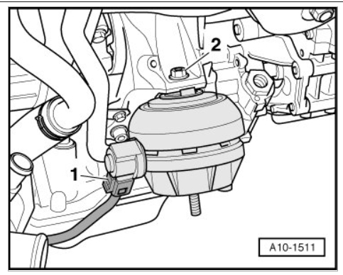
Disconnect electrical harness connector - 1 - at left engine mount.
Remove nut - 2 - and remove engine mount.
Remove the bolts - 1 and 2 -.
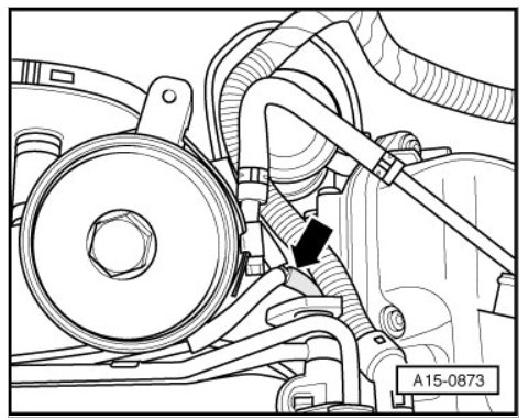
Remove return pipe from power-steering pump - arrow -.
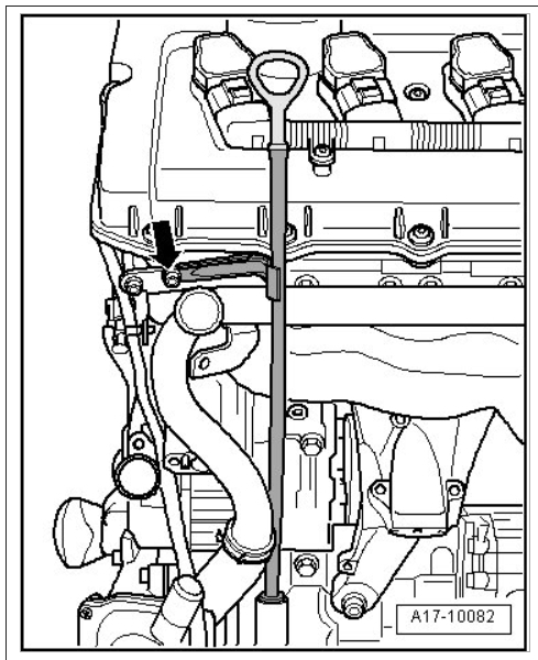
Remove guide pipe for oil dipstick at cylinder head - arrow -, pull up and remove.
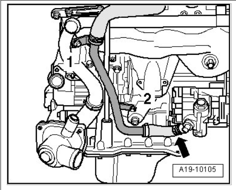
Remove the bolts - 1 and 2 -.
Loosen hose clamps - arrows - and remove left coolant pipe from coolant hoses.
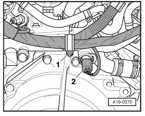
Remove the bolts - 1 and 2 -.
Loosen hose clamps - arrows - and remove right coolant pipe from coolant hoses.
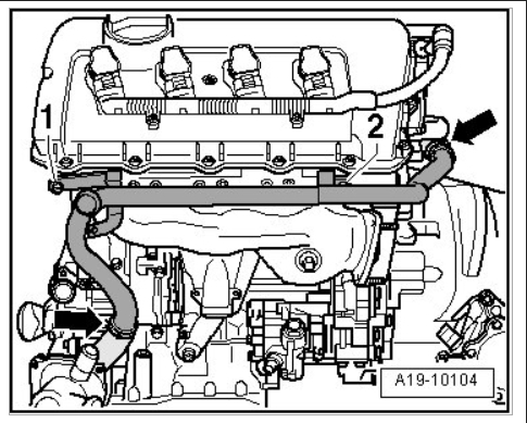
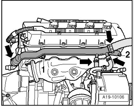
Disconnect electrical connector - 2 - on Engine Coolant Temperature (ECT) Sensor (G62).
Remove nut - 1 - and remove electrical wiring harness at rear coolant pipe.
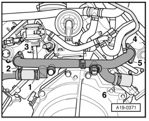
Remove the bolts - 2 through 5 -.
Remove rear coolant pipe.
¤ Ignore - 1 and 6 -.
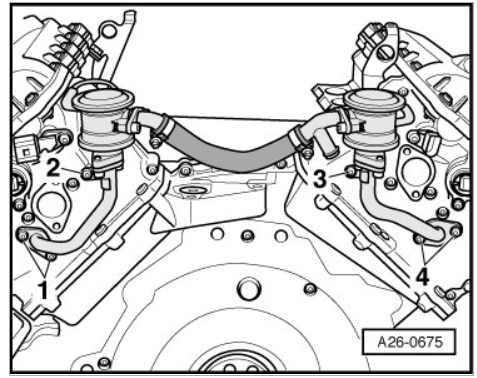
Remove Secondary Air Injection (AIR) system combi-valve mounting bolts - 1 through 4 -.
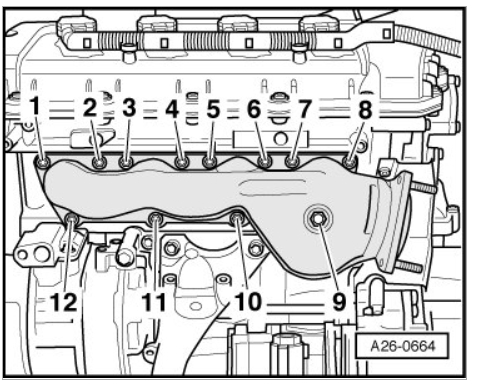
Remove nuts - 1 through 12 - and remove left exhaust manifold.
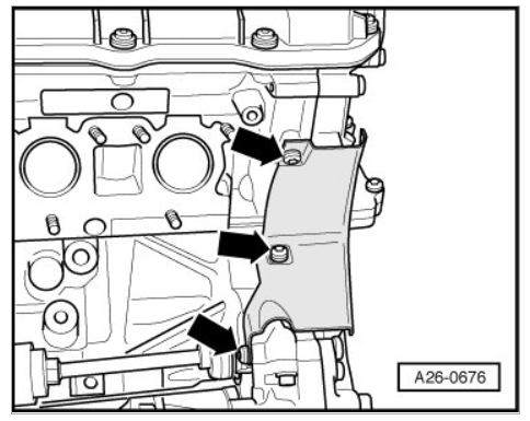
Remove left heat shield - arrows -.
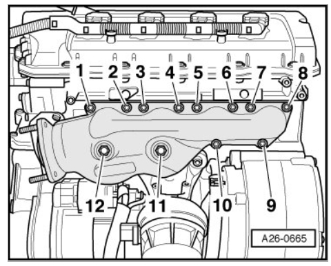
Remove nuts - 1 through 12 - and remove right exhaust manifold.
Remove right heat shield - arrows -.
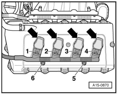
Remove bolts - 5 and 6 - on left cylinder head.
Disconnect electrical harness connectors - 1 through 4 -.
Remove ignition coils - arrows -.
¤ (T10094) can be used for removal.
Disconnect crankshaft housing ventilation hose - arrow -.
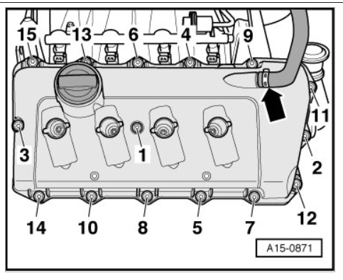
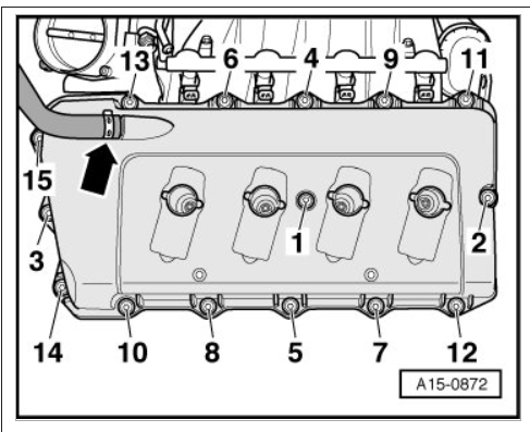
Remove left cylinder head cover bolts in sequence - 15 to 1 -.
Remove the cylinder head cover.
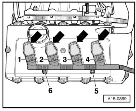
Remove bolts - 5 and 6 - on right cylinder head.
Disconnect electrical harness connectors - 1 through 4 -.
Remove ignition coils - arrows -.
¤ (T10094) can be used for removal.
Disconnect crankshaft housing ventilation hose - arrow -.
Remove right cylinder head cover bolts in sequence - 15 to 1 -.
Remove the cylinder head cover.
Disconnect electrical harness connector - arrow - for Camshaft Position (CMP) Sensor 2 (G163) on left cylinder head.
Disconnect electrical harness connector - arrow - for Camshaft Position (CMP) Sensor (G40) on right cylinder head.
Remove Ground (GND) cable - arrow - on right cylinder head.
Set wiring harness aside.
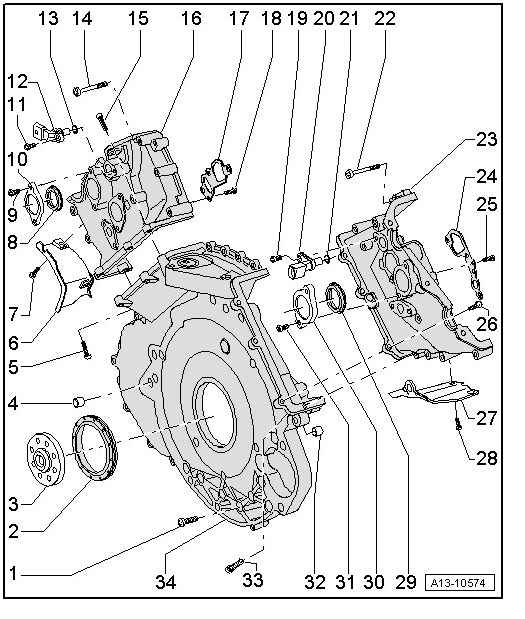
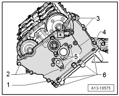
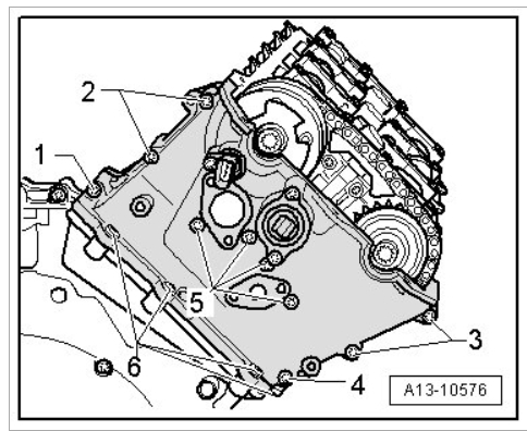
Remove the bolts - 1 through 6 - and the left timing chain guard.
Remove the bolts - 1 through 6 - and the right timing chain guard.
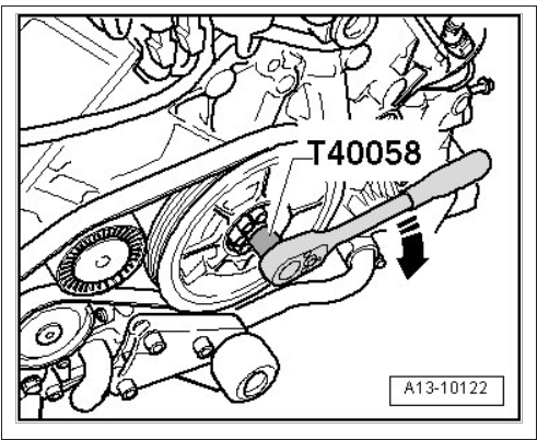
Using (T40058) , rotate crankshaft in direction of engine rotation - arrow - to TDC ignition timing.
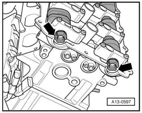
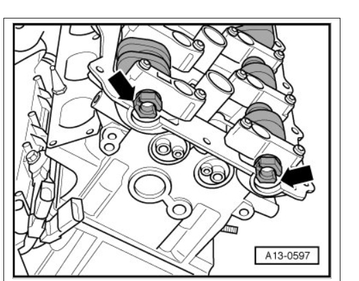
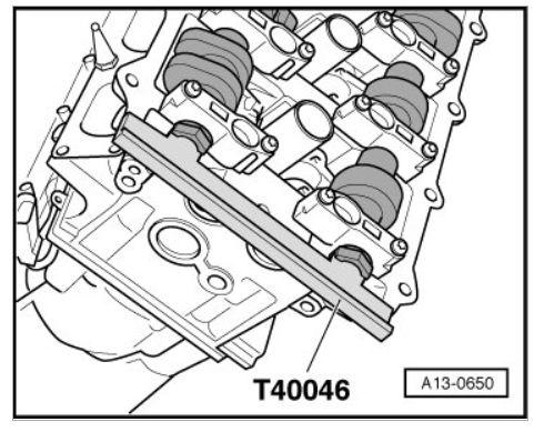
Slits - arrows - at front in camshafts must stand parallel at same height with upper edge of cylinder head.
Rotate camshafts at hex head slightly back or forth if necessary so that (T40046) can be inserted.
If (T40046) cannot be inserted, rotate crankshaft 1 rotation (360°) further.
Remove camshaft locator again.
Remove drain plug.
Install (3242) into hole, if necessary rotate crankshaft very slightly back and forth to completely center the holder. Tightening specifications: 20 Nm.
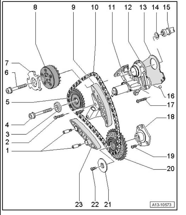
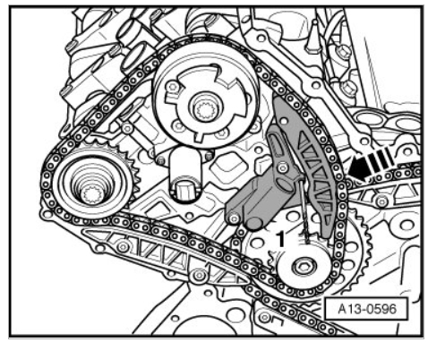
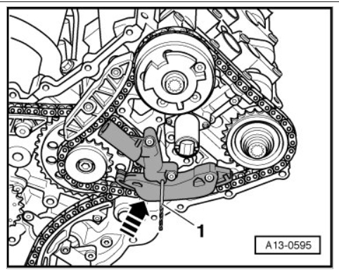
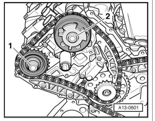
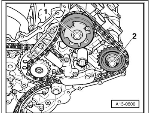
Push chain tensioner glide track for left timing chain in direction of - arrow - and pull off chain tensioner using a 3.3 mm drill bit - 1 -.
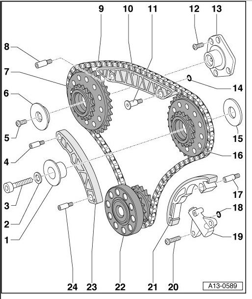
¤ In the following illustration, the timing mechanism is depicted with covers completely removed.
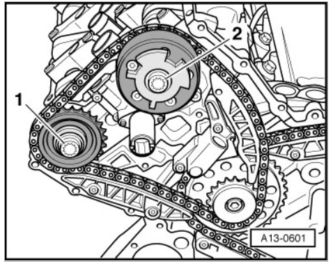
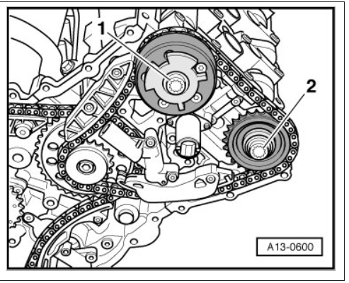
Remove bolts - 1 and 2 - for camshaft chain sprocket or camshaft adjuster using (T10035).
Remove camshaft chain sprocket and camshaft adjuster.
¤ Camshaft timing chain remains on engine.
¤ Also, if only one of the two cylinder heads is removed, bolts for camshaft gears must be loosened at both cylinder heads.
Push glide track of chain tensioner for right timing chain in direction of - arrow - and pull off chain tensioner using a 3.3 mm drill bit - 1 -.
Remove bolts - 1 and 2 - for the camshaft chain sprocket or camshaft adjuster using (T10035).
Remove camshaft chain sprocket and camshaft adjuster.
¤ Camshaft timing chain remains on engine.
¤ Also, if only one of the two cylinder heads is removed, bolts for camshaft gears must be loosened at both cylinder heads.
Installing
¤ Secure crankshaft in TDC position using (3242).
¤ During assembly, replace self-locking nuts and bolts.
¤ Always replace bolts that are tightened to torque as well as O-rings and gaskets.
¤ When turning camshaft, crankshaft must not be at TDC for any cylinder. Valves and/or pistons may be damaged.
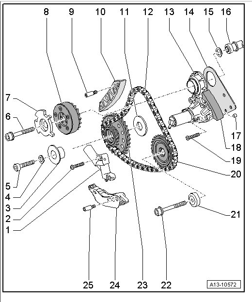
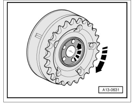
Rotate inner and outer part of both camshaft adjusters against each other up to lock position - arrows -.
¤ Inner and outer part must not be able to be against each other in lock position (slight play can still be felt).
Check whether camshafts of both cylinder heads stand in TDC position.
¤ Slits - arrows - at front in camshafts must stand parallel at same height with upper edge of cylinder head.
Insert (T40046) into camshafts of left cylinder head, to do so rotate camshafts back or forth at hex head if necessary.
Insert (T40046) into camshafts of right cylinder head, to do so rotate camshafts back or forth at hex head if necessary.
Replace all four camshaft bolts.
Assemble left timing chain with chain sprocket and camshaft adjuster.
Loosely install bolts - 1 and 2 -.
¤ Chain sprocket and camshaft adjuster must be able to still be rotated on camshaft and must not tip.
Assemble the right timing chain with chain sprocket and camshaft adjuster.
Loosely install bolts - 1 and 2 -.
¤ Chain sprocket and camshaft adjuster must be able to still be rotated on the camshaft and must not tip.
Remove (3242).
Using (T40058) , rotate crankshaft approximately 30°in opposite direction of engine rotation - arrow -.
Pull drill bit out of the alignment hole, which loosens the left chain tensioner.
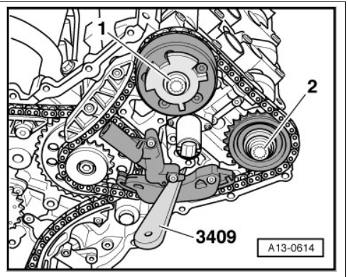
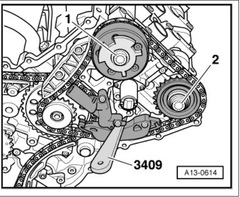
Insert (3409) as depicted in illustration and bring chain tensioner into contact with (3409).
¤ Lightly pressing in an extra 0.5 mm is permitted.
Pull drill bit out of the alignment hole, which loosens the right chain tensioner.
Insert (3409) as depicted in the illustration and bring chain tensioner into contact with (3409).
¤ Lightly pressing in an extra 0.5 mm is permitted.
Using (T40058) , rotate crankshaft in direction of engine rotation - arrow - to TDC ignition timing.
¤ If rotated unintentionally beyond TDC, turn back crankshaft again approximately 30°and set to TDC again.
Install (3242) into hole, if necessary rotate crankshaft very slightly back and forth to completely center the holder. Tightening specifications: 20 Nm.
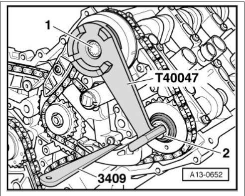
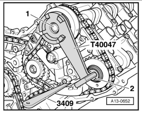
Tighten camshaft bolt - 1 - on exhaust camshaft of the left cylinder head to initial tightening specifications. Tightening specifications: 40 Nm.
Secure hall sensor wheel on the intake camshaft adjuster of the left cylinder head using (T40047).
Place (T40047) on bolt - 1 -.
Tighten camshaft bolt - 2 - on intake camshaft to initial tightening specifications. Tightening specifications: 40 Nm.
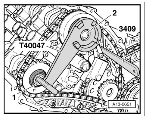
Secure hall sensor wheel on intake camshaft adjuster of the right cylinder head using (T40047).
Place (T40047) on bolt - 2 -.
Tighten camshaft bolt - 1 - on intake camshaft to initial tightening specifications. Tightening specifications: 40 Nm.
Remove setting gauge.
Tighten camshaft bolt - 2 - on the exhaust camshaft of the right cylinder head to initial tightening specifications. Tightening specifications: 40 Nm.
¤ (T40046) must not be used as counter holder for final tightening of the camshaft bolts.
Remove (T40046) on both cylinder heads.
Tighten camshaft bolt - 1 - on exhaust camshaft of the left cylinder head to final tightening specifications. Tightening specifications: 100 Nm + 90°(1/4 turn).
Secure hall sensor wheel on the intake camshaft adjuster of the left cylinder head using (T40047).
Place (T40047) on bolt - 1 -.
Tighten camshaft bolt - 2 - on the intake camshaft to final tightening specifications. Tightening specifications: 100 Nm + 90°(1/4 turn).
Secure hall sensor wheel on intake camshaft adjuster of the right cylinder head using (T40047).
Place (T40047) on bolt - 2 -.
Tighten camshaft bolt - 1 - on the intake camshaft to final tightening specifications. Tightening specifications: 100 Nm + 90°(1/4 turn).
Remove setting gauge.
Tighten camshaft bolt - 2 - on the exhaust camshaft of the right cylinder head to final tightening specifications. Tightening specifications: 100 Nm + 90°(1/4 turn).
Remove (3242).
Using (T40058) turn the crankshaft two complete rotations in direction of engine rotation - arrow - until crankshaft stands at TDC again.
¤ Slits - arrows - at front in camshafts must stand parallel at the same height with upper edge of cylinder head.
Install the (3242) in the hole (20 Nm). Rotate the camshaft back and forth slightly if necessary to completely center the holder.
Insert (T40046) into camshafts of the left cylinder head.
Insert (T40046) into camshafts of right cylinder head.
¤ If (T40046) cannot be inserted, repeat adjustment.
Pull out (3409).
Remove (T40046) on both cylinder heads.
Remove (3242).
Install sealing plug of TDC marking with new sealing ring into upper oil pan.
Further installation is performed in reverse order of removal, noting the following:
Install covers for timing chains => [ Installing ] See: Timing CoverService and Repair.
Bolt transmission to engine and install engine/transmission. Refer to => [ Engine, Installing ] See: Service and RepairRemoval and ReplacementEngine, Installing.
Tightening Specifications.
Let us know what happens and please upload pictures or videos of the problem.
Cheers, Ken
Images (Click to enlarge)
Nov 8, 2017 at 12:31 PM