Camshaft Timing procedure

Tiny
RAMONER1
  • MEMBER
  • 2004 ISUZU RODEO
  • 3.5L
  • V6
  • 4WD
  • AUTOMATIC
  • 115,000 MILES
Hi, have a recently purchased this vehicle with direct injection. I have learned they were only in production the last ten months of the production of the Rodeo. Everything before being standard fuel injection. So the problem I am having trouble with it, it backfires loud and does not run for more than a couple seconds. I was told the timing belt was replaced but never ran again and left in the condition it is now. The other problem is that the heads are different from what I have seen in pictures and videos. There is no idler gear on either head. Both IN and EX cam sprockets mesh directly to each other on each head. It now sits with timing belt off and valve covers off. My guess to the problem would be that the timing procedure is different for these GDI's considering the different heads and was performed with the standard injection style procedure on the first attempt. I do not know for sure but this where I am at. Any help is appreciated.
Monday, August 27th, 2018 AT 6:39 PM

14 Replies

Tiny
JACOBANDNICKOLAS
  • MECHANIC
  • 108,300 POSTS
Hi and thanks for using 2CarPros. Com.

Here are the timing belt replacement directions from Alldata. I hope it is what you needed. All attached pictures correlate with these (extensive) directions.
______________________________

iming Belt
Removal
1. Disconnect battery ground cable.
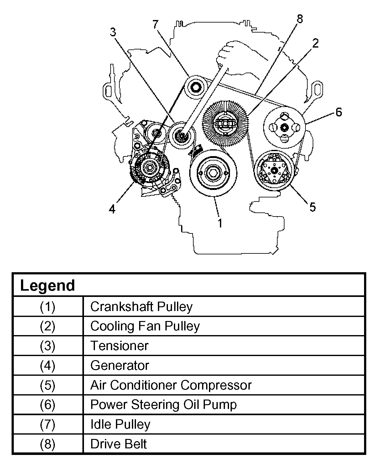
2. Remove air cleaner assembly.
3. Remove radiator upper fan shroud from radiator.
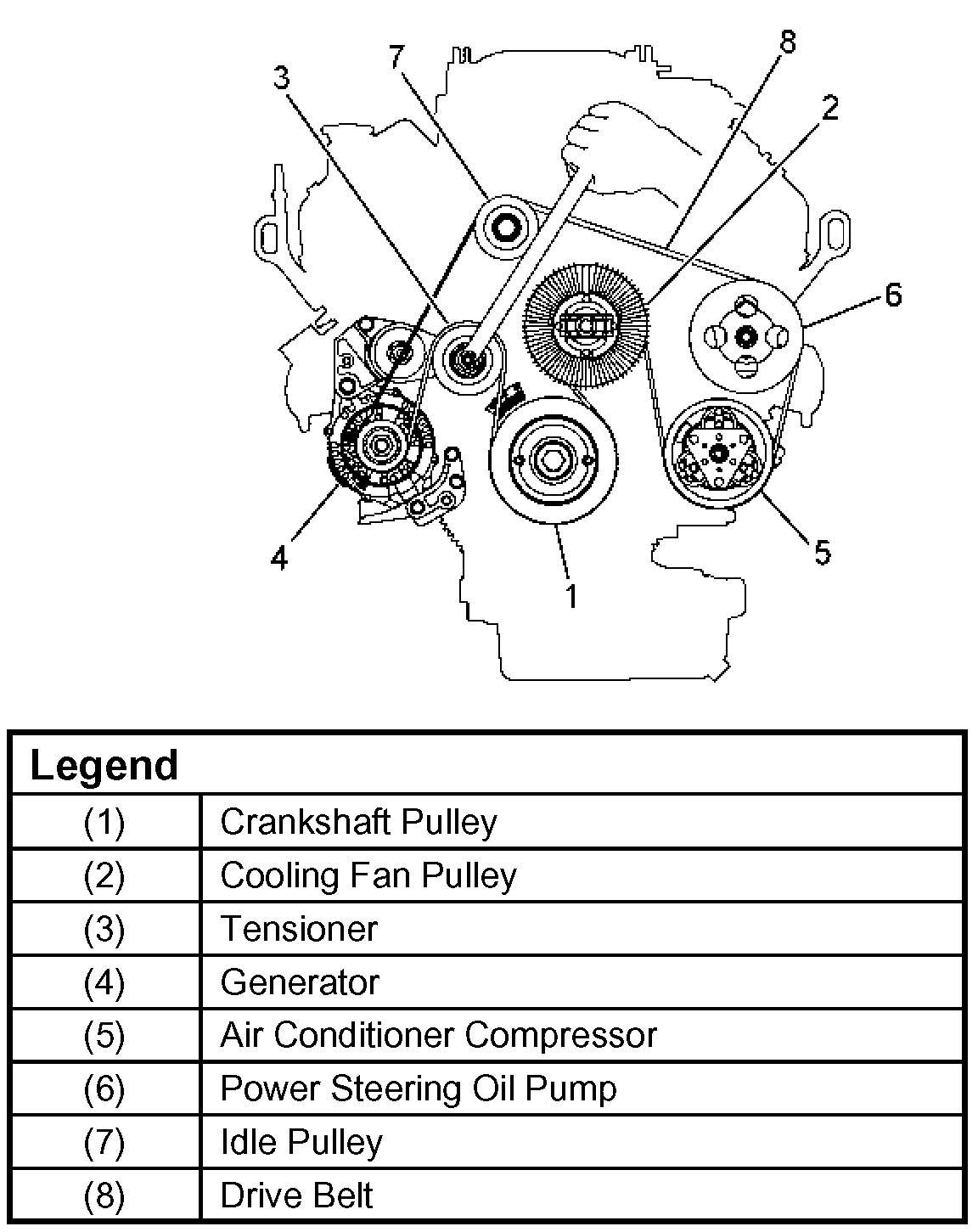
4. Move drive belt tensioner to loose side using wrench then remove drive belt.
5. Remove cooling fan assembly four nuts, then the cooling fan assembly.
6. Remove cooling fan drive pulley assembly.
7. Remove idle pulley assembly.
8. Remove serpentine belt tensioner assembly.
9. Remove crankshaft pulley assembly using J-8614-01 crankshaft holder, hold crankshaft pulley remove center bolt, then the pulley.
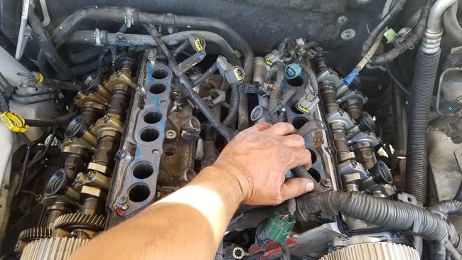
10. Disconnect harness connector of right side timing belt cover front side.
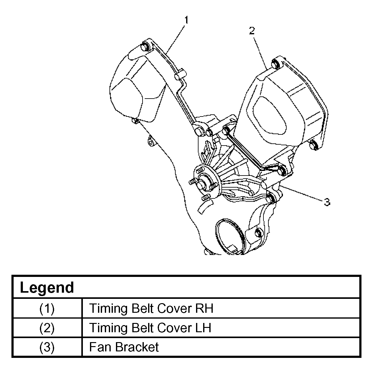
11. Remove right side timing belt cover and left side timing belt cover.
12. Remove fan bracket.
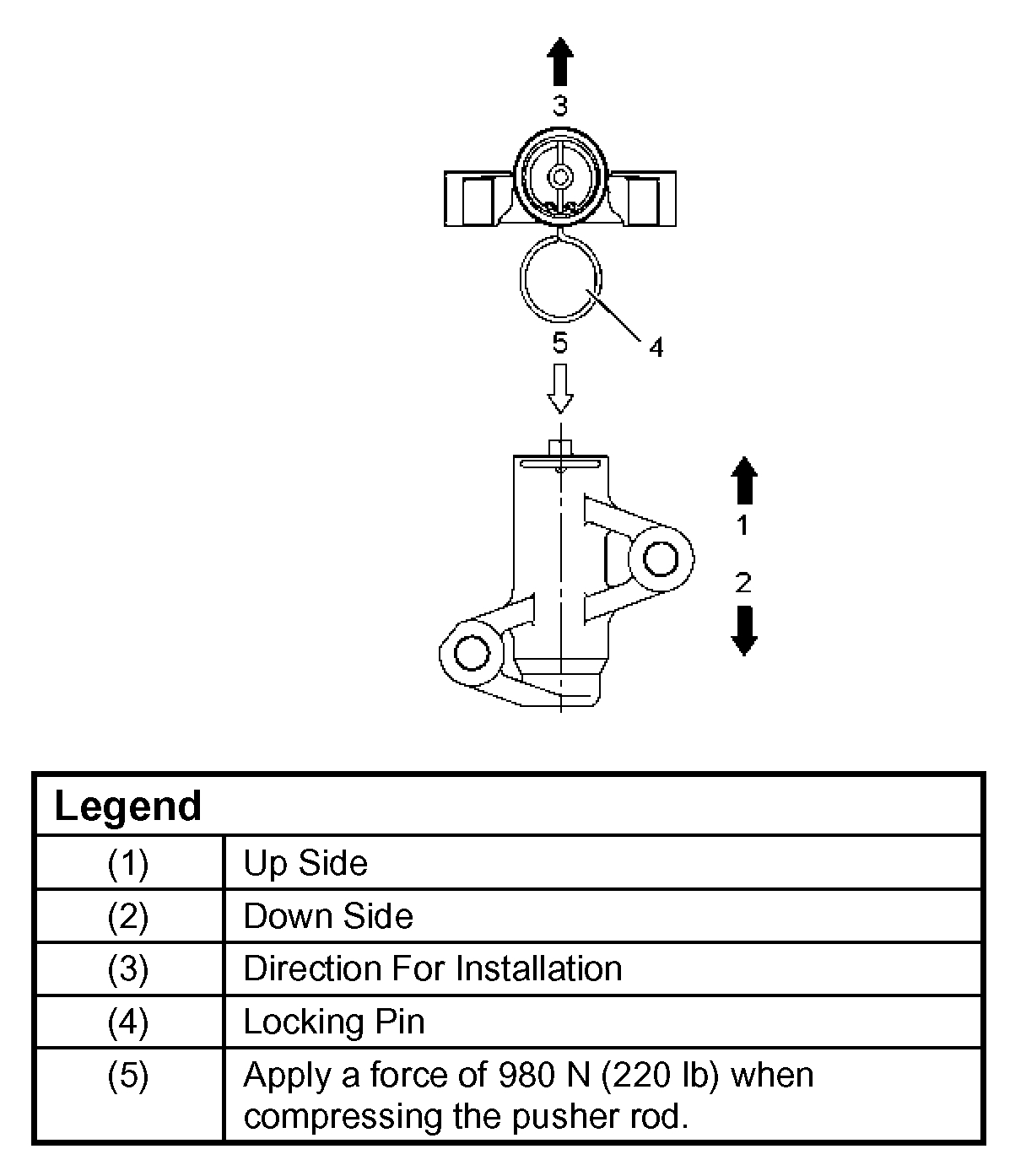
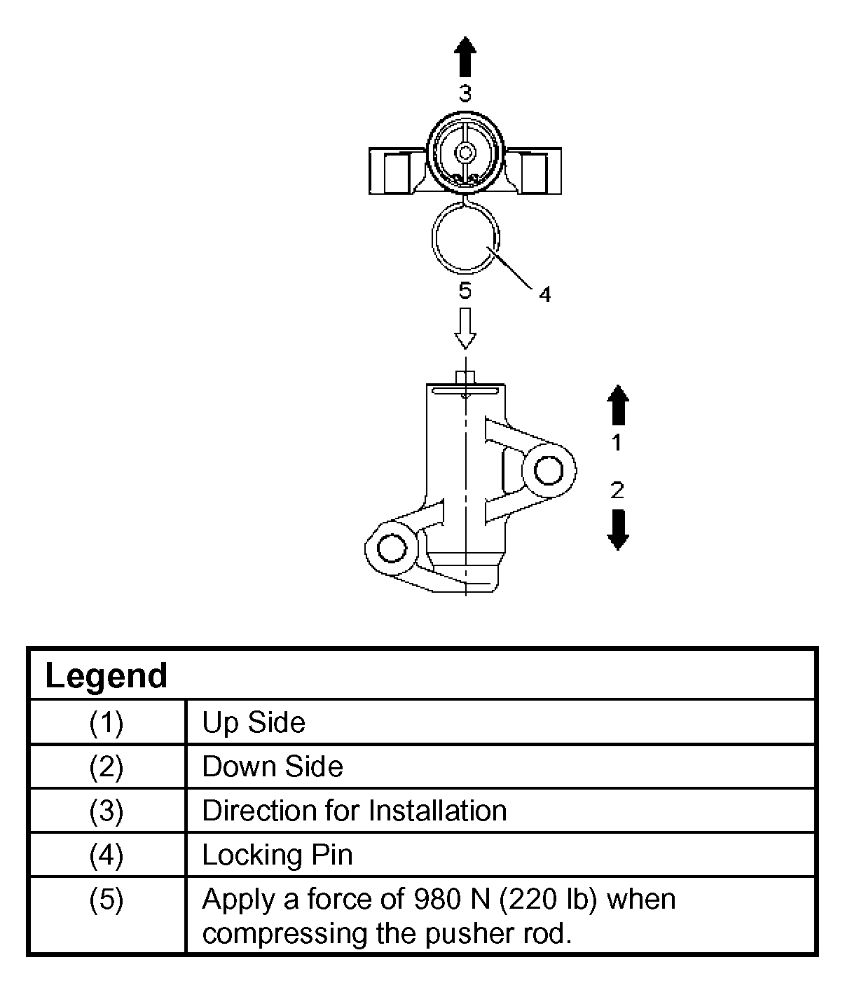
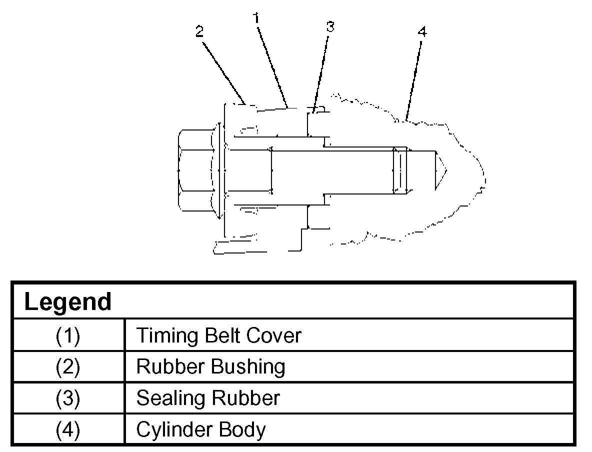
13. Remove pusher.

CAUTION: The pusher prevents air from entering the oil chamber. Its rod must always be facing upward.

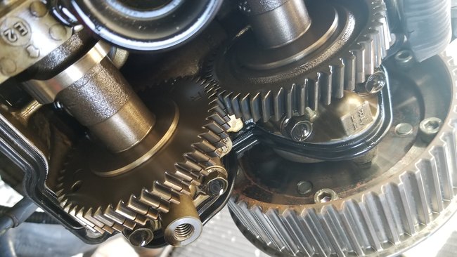
14. Remove timing belt.

CAUTION:
1. Do not bend or twist the belt, otherwise its core could be damaged. The belt should not be bent at a radius less than 30 mm (1.2 inch).
2. Do not allow oil or other chemical substances to come in contact with the belt. They will shorten the life.
3. Do not attempt to pry or stretch the belt with a screw driver or any other tool during installation.
4. Store timing belt in a cool and dark place. Never expose the belt direct sunlight or heat.

Installation
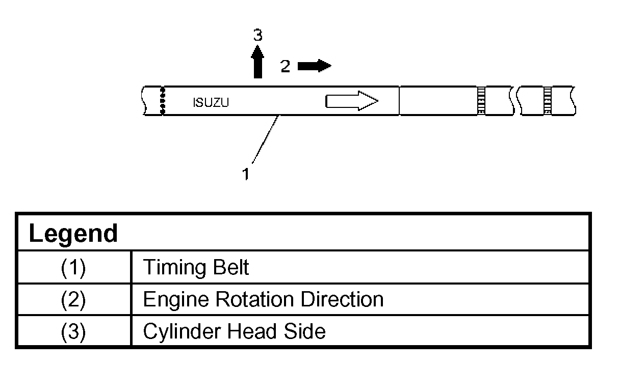
Note: For correct belt installation, the letter on the belt must be able to be read as viewed from the front of the vehicle.

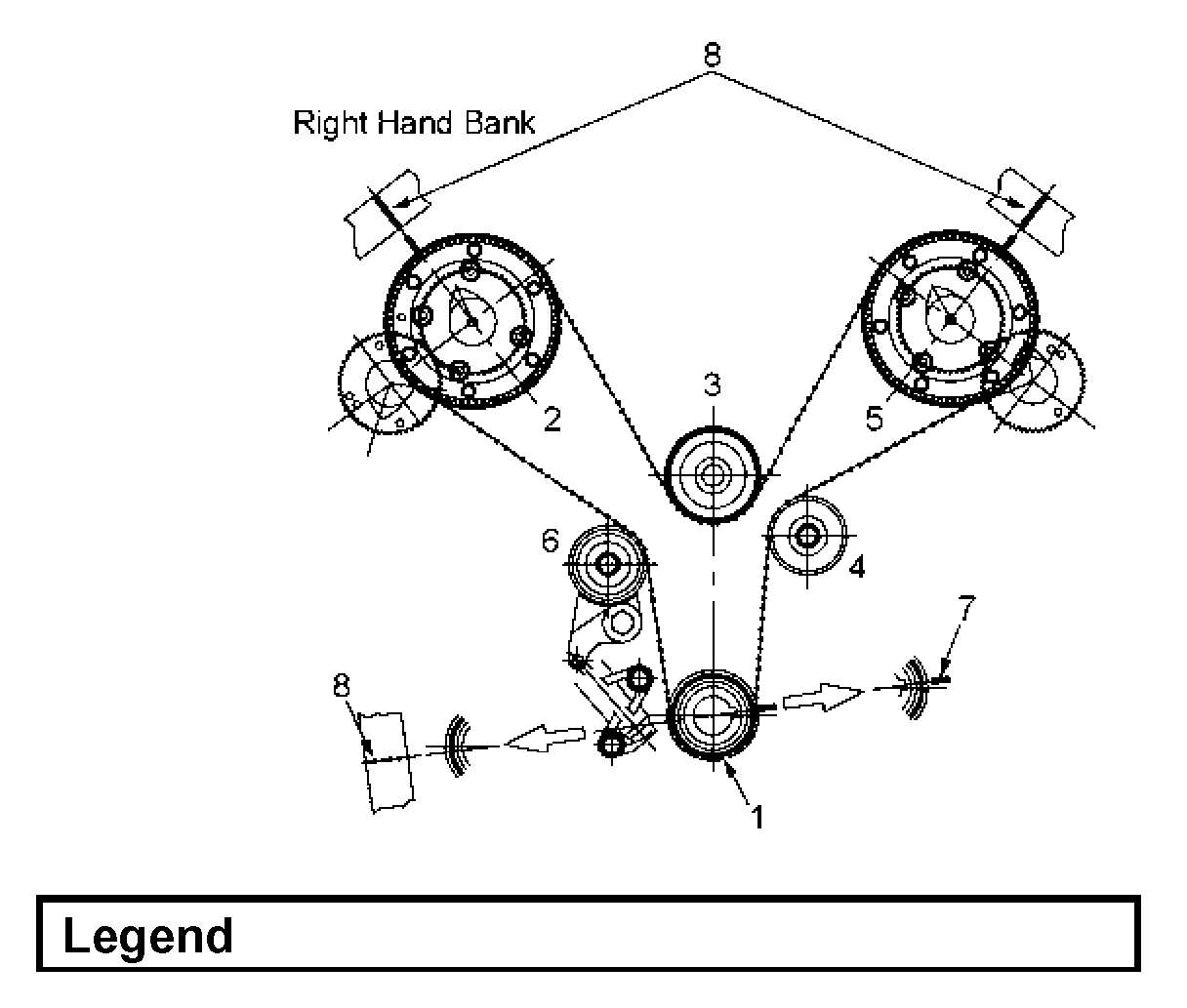
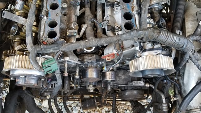
1. Install timing belt.
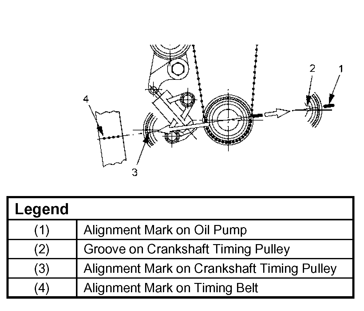
1. Align groove of crankshaft timing pulley (2) with mark on oil pump (1).
Align the mark on the crankshaft timing pulley (3) with alignment mark (white dotted line) on the timing belt (4).
Secure the belt with a double clip or equivalent clip.

Note: When timing marks are aligned, No.2 piston will be on Top Dead Center.

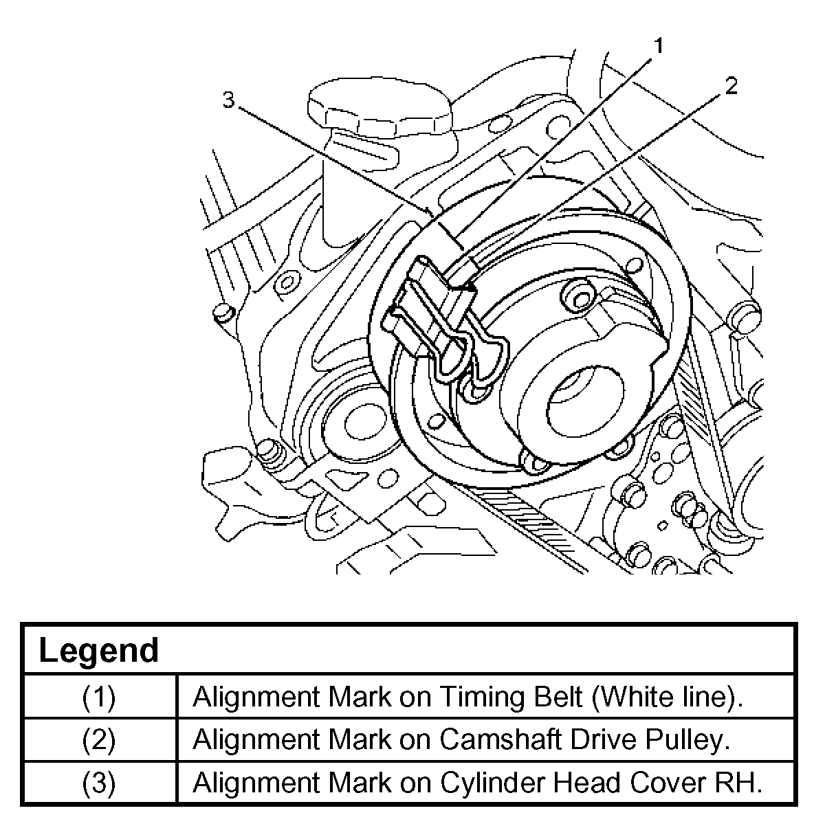
2. Align the alignment mark on the RH bank camshaft drive pulley (2) to the alignment mark of the cylinder head cover RH (3).
The camshaft pulley alignment mark should also align with alignment mark on the cylinder head cover.
3. Align the alignment mark (white line) on the timing belt (1) with alignment mark on the RH bank camshaft drive pulley (2) (on the left side as viewed from the front of the vehicle) and put the timing belt on the camshaft drive pulley.
Secure the belt with a double clip or equivalent clip.
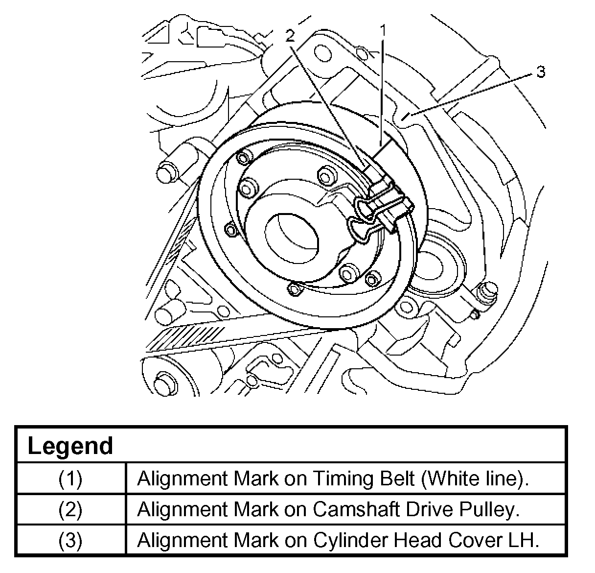
4. Align the alignment mark on the LH bank camshaft drive pulley (2) to the alignment mark of the cylinder head cover LH (3).
The camshaft pulley alignment mark should also align with alignment mark on the cylinder head cover.
5. Align the alignment mark (white line) on the timing belt (1) with the alignment mark on the LH bank camshaft drive pulley (2).
When aligning the timing marks, use a wrench to turn the camshaft drive pulley, then set the timing mark between timing belt and camshaft drive pulley and put the timing belt on the camshaft drive pulley.
Secure the belt with a double clip or equivalent clip.

Note: It is recommended for easy installation that the belt be secured with a double clip or equivalent clips after it is installed to each pulley.

6. Install crankshaft pulley temporarily and tighten center bolt by hand (do not use a wrench).
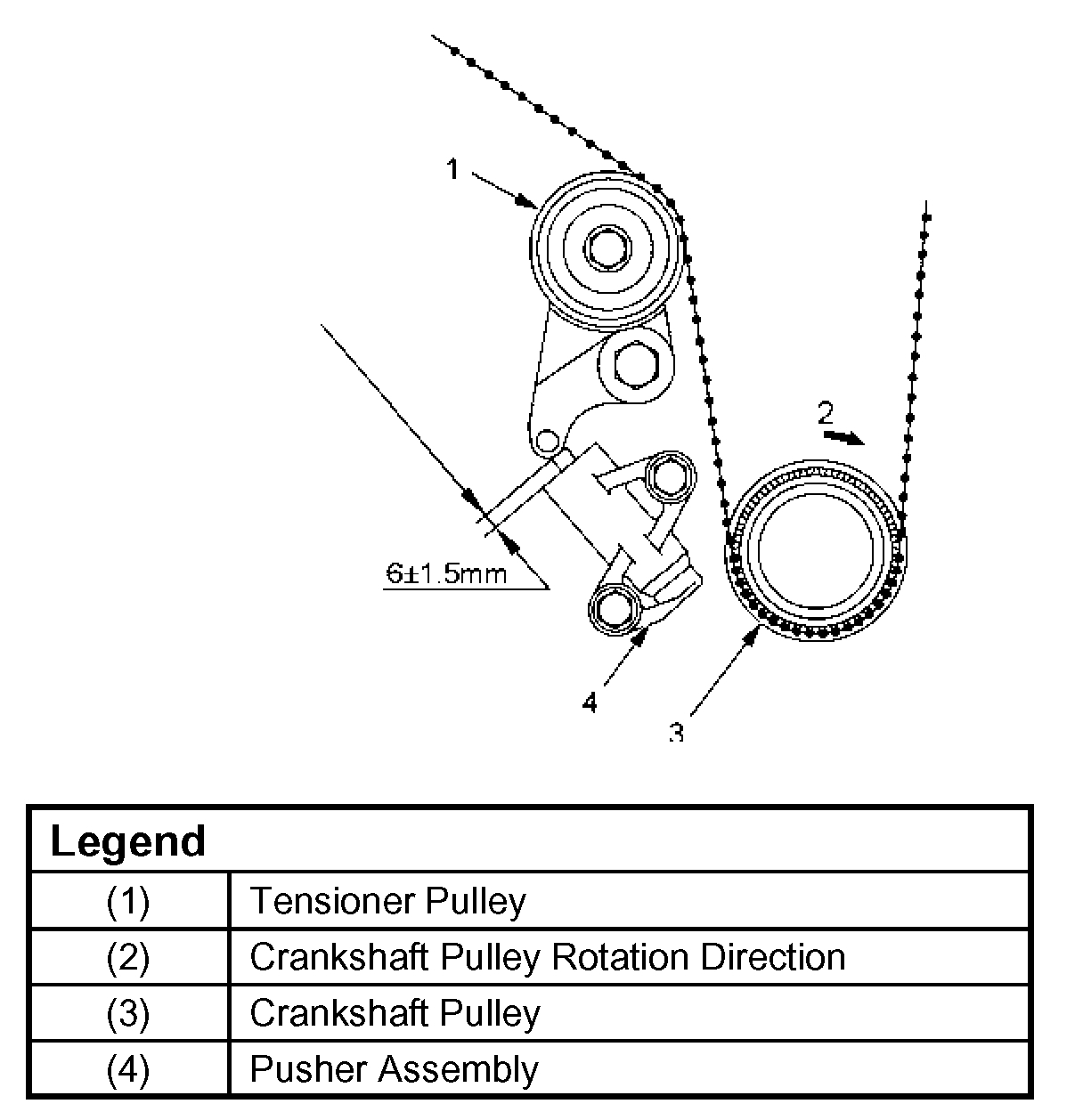
Turn the crankshaft pulley clockwise to give some belt slack between the crankshaft timing pulley and the RH bank camshaft drive pulley.
2. Install pusher and tighten bolt to the specified torque.
Torque: 25 Nm (18.4 ft. Lbs.)
1. Install the pusher while pushing the tension pulley to the belt.
2. Pull out pin from the pusher.

Note: When reusing the pusher, press the pusher with approximately 100 Kg to retract the rod, and insert a pin (1.4 mm (0.055 inch) piano wire).
After release the push rod from the locking pin, the rod projection is approximate 6 mm (0.2362 inch).
3. Remove double clips or equivalent clips from timing belt pulleys.
Turn the crankshaft pulley by six turns and check for timing mark alignment.
3. Install fan bracket and tighten fixing bolts to the specified torque.
Torque: 22 Nm (16 ft. Lbs.)
4. Install timing belt cover.
Remove crankshaft pulley that was installed in step 1 item 5.
Tighten bolts to the specified torque.
Torque: 19 Nm (14 ft. Lbs.)
5. Install crankshaft pulley using J-8614-01, hold the crankshaft pulley and tighten center bolt to the specified torque.
Torque: 167 Nm (123 ft. Lbs.)
Torque:
M8 bolt: 22 Nm (16 ft. Lbs.)
M10 bolt: 46 Nm (34 ft. Lbs.)
6. Install cooling fan assembly and tighten bolts/nuts to the specified torque.
Torque: 22 Nm (16 ft. Lbs.) For fan pulley and fan bracket.
Torque: 10 Nm (7.4 ft. Lbs.) For fan and clutch assembly.
7. Move drive belt tensioner to loose side using wrench, then install drive belt to normal position.
8. Install radiator upper fan shroud.
9. Install air cleaner assembly.

________________________________________

I hope this helps. Let me know if it is incorrect for your application.

Take care,
Joe
Was this
answer
helpful?
Yes
No
+1
Monday, August 27th, 2018 AT 7:22 PM
Tiny
RAMONER1
  • MEMBER
  • 8 POSTS
Thank you. But I need to know how to put it back in time as if replacing a broken belt. Also, like I said these heads are different. They do not have an idler gear in between the in and ex cam gears. They are in direct mesh. I have not found a timing procedure for a 3.5l with that type of head I have. Where would I line those marks up in relation to the marks on the cam sprocket that the timing belt goes on?
Was this
answer
helpful?
Yes
No
+3
Tuesday, August 28th, 2018 AT 2:18 AM
Tiny
RAMONER1
  • MEMBER
  • 8 POSTS
No idler gear.
Was this
answer
helpful?
Yes
No
+5
Tuesday, August 28th, 2018 AT 2:20 AM
Tiny
JACOBANDNICKOLAS
  • MECHANIC
  • 108,300 POSTS
If you look at picture number 3, it shows the design you have. I have reattached the picture here. It has a belt pulley on one of the cams and the are mesh together directly. Double check what I sent. I checked both of my manuals and they are both the same as I sent.
Was this
answer
helpful?
Yes
No
+4
Tuesday, August 28th, 2018 AT 6:01 PM
Tiny
RAMONER1
  • MEMBER
  • 8 POSTS
Thank you sir for the quick response. Greatly appreciated.
Was this
answer
helpful?
Yes
No
+1
Tuesday, August 28th, 2018 AT 6:12 PM
Tiny
JACOBANDNICKOLAS
  • MECHANIC
  • 108,300 POSTS
You are welcome. However, did it help? If not I can continue research.

Let me know. I hope it was what was needed.

Take care,
Joe
Was this
answer
helpful?
Yes
No
+1
Tuesday, August 28th, 2018 AT 8:12 PM
Tiny
RAMONER1
  • MEMBER
  • 8 POSTS
Solved. Could not have done it without that diagram. Thanks again. The problem turned out to be incorrect cam installation. I noticed the drivers side head had been replaced at one point judging by the cleanliness and one of the journal caps being out of place. So I checked cam positions and the ex cam timing marks were off by 90°. Putting it back together today. See how it runs.
Was this
answer
helpful?
Yes
No
+1
Thursday, September 6th, 2018 AT 8:06 AM
Tiny
KEN L
  • MASTER CERTIFIED MECHANIC
  • 43,047 POSTS
Please let us know. :)
Was this
answer
helpful?
Yes
No
Saturday, September 8th, 2018 AT 12:38 PM
Tiny
RAMONER1
  • MEMBER
  • 8 POSTS
Starts up like it should but there is damage. I believe the valves are most likely bent but would like an expert opinion for better confirmation. So, valves and gaskets are on there way and will be tackling this in a few days. But as for the timing issue, yes that has been fixed.
Was this
answer
helpful?
Yes
No
Saturday, September 8th, 2018 AT 7:37 PM
Tiny
KEN L
  • MASTER CERTIFIED MECHANIC
  • 43,047 POSTS
Thanks for the video. The valves look fine it would have a rough idle if the engine was hurt. I would change the oil and filter to see what what happens. I noticed the check engine light blinking in the video?

https://www.2carpros.com/articles/how-to-change-engine-oil-and-filter

and

https://www.2carpros.com/articles/checking-a-service-engine-soon-or-check-engine-light-on-or-flashing

Please run down these guides and report back.

Cheers, Ken
Was this
answer
helpful?
Yes
No
+1
Sunday, September 9th, 2018 AT 12:17 PM
Tiny
RAMONER1
  • MEMBER
  • 8 POSTS
Got it tore down again at the passenger side head to check and replace valves. Head bolts and everything are out. Front end of the head picks up but its stuck somewhere in the rear to where I cannot get it out. There is a high pressure fuel pump that is attached to the head. Looks and feels like it should come off with the head and I do not want to remove unless I have to because one of the mounting bolts is rounded. I need a removal procedure off of AllData.
Was this
answer
helpful?
Yes
No
Tuesday, September 11th, 2018 AT 2:42 PM
Tiny
KEN L
  • MASTER CERTIFIED MECHANIC
  • 43,047 POSTS
Yes, there is a bolt in the rear of the head down low. Here are the cylinder head removal instructions below.

Check out the diagrams (below). Please let us know what happens.

Cheers, Ken
Was this
answer
helpful?
Yes
No
+1
Wednesday, September 12th, 2018 AT 10:16 AM
Tiny
RAMONER1
  • MEMBER
  • 8 POSTS
Thanks Ken. Would have wasted a lot more time without your diagram. So got all the valves changed (which were perfectly fine other than a slot of carbon build up), new head gaskets. All buttoned up. Started right up and sounded exactly the same as in the video. Drove it a mile down the road to put $10.00 in it. It was on E. Found it had a small fuel leak in the fuel rail connections. Took the intake off and back on to fix it. Now, not sure if it had anything to do with it but now it just cranks without starting. No spark (in-line tester) with a p0346 (I have the Torque app now). Has fuel (Torque says 57 psi) and injector pulse (Noid Light). Checked wiring and grounds around the intake. Both cams and crank have a 5 volts ref (Power Probe). Stuck and ready to drive it off a hill. What are your thoughts guys?
Was this
answer
helpful?
Yes
No
Tuesday, September 18th, 2018 AT 12:12 PM
Tiny
KEN L
  • MASTER CERTIFIED MECHANIC
  • 43,047 POSTS
This is a camshaft code now. When you crank the engine over does it sounds normal? Or did the timing belt come loose and now the camshafts are not turning? Will it run on starting fluid?
Was this
answer
helpful?
Yes
No
Wednesday, September 19th, 2018 AT 4:23 PM

Please login or register to post a reply.

Sponsored links