Marlio,
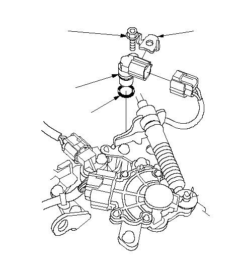
True it is the same vehicle as the Fit, however the US didn't get the CVT version until 2015 and the power-train is much different for the US. However, I did find a factory service manual for that vehicle. The speed sensor in question is located under the air cleaner housing. Shown in the first picture. Remove the air box and duct and the sensor is next to the shift input cable. I would check the connector to see if there is any corrosion or damage. Also check the harness for damage. If they look good replace the sensor.
Here is the troubleshooting guide for that code:
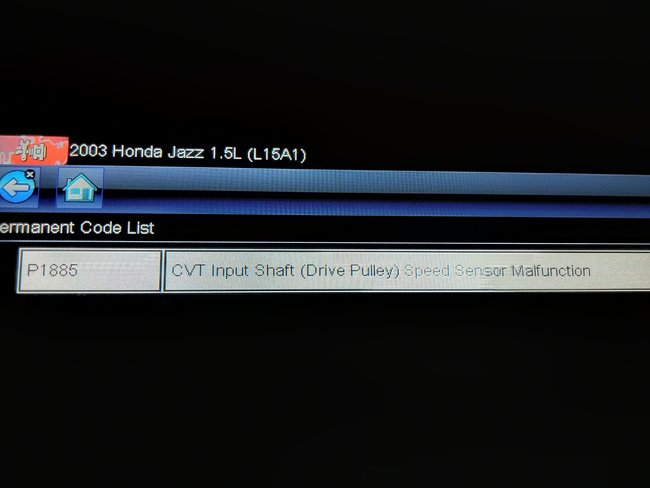
DTC P1885: Problem in CVT Drive Pulley Speed Sensor Circuit
1. Turn the ignition switch OFF.
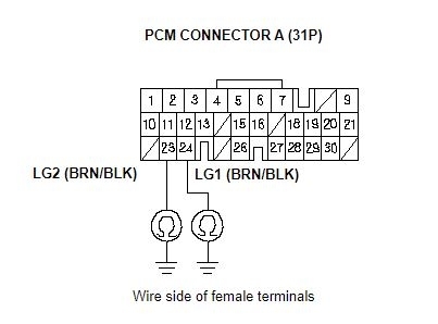
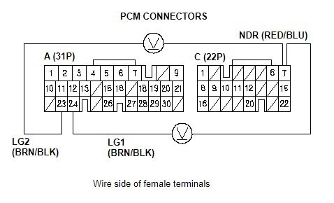
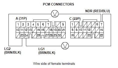
2. Check for continuity between PCM connector terminal A23 and body ground, and between terminal A24 and body ground.
See Pic 2
Continuity on both?
YES - Go to 4.
NO - Repair open in the wire PCM connector terminals A23 and A24, and ground (G101), or repair poor ground (G101).
4. Disconnect CVT drive pulley speed sensor connector.
5. Turn the ignition switch ON (II).
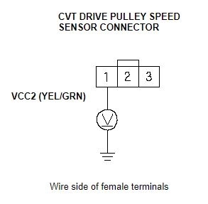
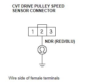
6. Measure the voltage between CVT drive pulley speed sensor connector terminal No. 1 and body ground.
See Pic 3
Is there about 5 V?
YES - Go to 7.
NO - Go to 20.
7. Turn the ignition switch OFF.
8. Disconnect the battery negative terminal.
9. Disconnect PCM connector C (22P).
10. Check for continuity between CVT drive pulley speed sensor connector terminal No. 2 and body ground.
See Pic 4
Is there continuity?
YES - Repair short to ground in the wire between PCM connector C7 and the CVT drive pulley speed sensor connector.
NO - Go to 11.
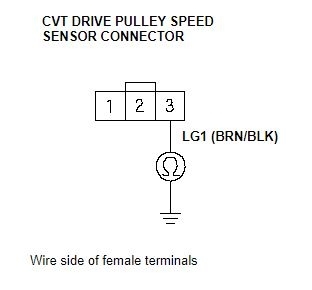
11. Check for continuity between CVT drive pulley speed sensor connector terminal No. 3 and body ground.
See Pic 5
Is there continuity?
YES - Go to 12.
NO - Repair open in the wire between the CVT drive pulley speed sensor connector terminal No. 3 and ground (G101), or repair poor ground (G101).
12. Reconnect PCM connector C (22P), then reconnect the battery negative terminal.
13. Turn the ignition switch ON.
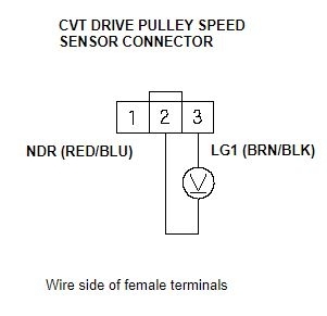
14. Measure the voltage between CVT drive pulley speed sensor connector terminals No. 2 and No. 3.
See Pic 6
Is there about 5 V?
YES - Go to 15.
NO - Go to 25.
15. Connect CVT drive pulley speed sensor connector.
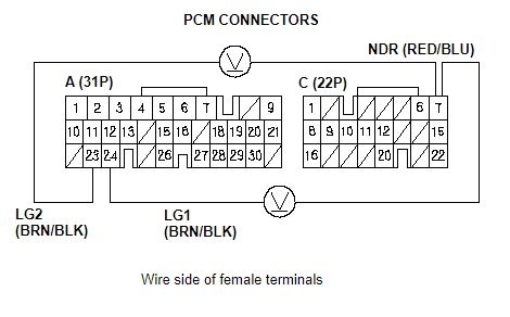
16. Measure the voltage between PCM connector terminals C7 and A23 or A24.
See Pic 7
Is there about 0 V or 5 V?
YES - Go to 17.
NO - Replace the CVT drive pulley speed sensor.
17. Shift to [P] position.
18. Start the engine, and let it idle.
19. With engine idling, measure the voltage between PCM connector terminals C7 and A23 or A24.
See Pic 8
Is there 1.5-3.5 V?
YES - Check for loose terminal fit in the PCM connectors. If necessary, substitute a known-good PCM and recheck.n
NO - Replace the CVT drive pulley speed sensor.
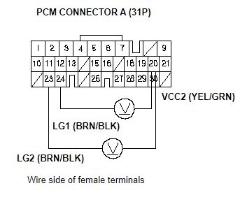
20. Measure the voltage between PCM connector terminals A20 and A23 or A24.
See Pic 9
Is there 4.75-5.25 V?
YES - Repair open in the wire between PCM connector terminal A20 and the CVT drive pulley speed sensor connector.
NO - Go to 21.
21. Turn the ignition switch OFF.
22. Disconnect the battery negative terminal.
23. Disconnect PCM connector A (31P).
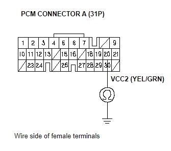
24. Check for continuity between PCM connector terminal A20 and body ground.
See Pic 10
Is there continuity?
YES - Repair short to ground in the wire between PCM connector terminal A20 and the CVT drive pulley speed sensor connector.
NO - Check for loose terminal fit in the PCM connectors. If necessary, substitute a known-good PCM and recheck.
25. Measure the voltage between PCM connector terminals C7 and A23 or A24.
See Pic 11
Is there about 5 V?
YES - Repair open in the wire between PCM connector terminal C7 and the CVT drive pulley speed sensor connector.
NO - Check for loose terminal fit in the PCM connectors. If necessary, substitute a known-good PCM and recheck.
Images (Click to enlarge)
Feb 13, 2020 at 2:18 PM