Hi,
This is going to require some diagnostics. It seems by accident something was damaged when you removed and cleaned the unit. Since the codes are specific to the throttle control module and the throttle position sensor (TPS) that is where we need to start. Additionally, the codes indicate a communication issue between the two. I am going to provide diagnostic flow charts. Work through them in order and see if you can identify the possible source of the problem. Also, just reconfirm there are no damaged wires from the TPS. It is easy to accidentally pinch one or cause one to short when working. The module related code is specific to a short to B+ voltage. I have a feeling that is the issue, a short to power.
_______________________________-
Here are the diagnostics for the P120. We need to start there. The attached pics will indicate the tests involved. Note that the diagnostics are very similar with the P0220.
_______________________________
2003 GMC Truck K 1500 Yukon 4WD V8-5.3L VIN T
P0120
Vehicle ALL Diagnostic Trouble Codes ( DTC ) Testing and Inspection P Code Charts P0120
P0120
CIRCUIT DESCRIPTION
The throttle position (TP) sensor 1 is a potentiometer type sensor with three circuits:
- A 5-volt reference circuit
- A low reference circuit
- A signal circuit
The TP sensor is used to determine the throttle plate angle for various engine management systems. The control module provides the TP sensor a 5-volt reference circuit and a low reference circuit. The TP sensor then provides the control module a signal voltage proportional to throttle plate movement. TP sensor 1 signal voltage is low at closed throttle and increases as the throttle opens. When the control module detects that the TP sensor 1 signal or TP sensor 5-volt reference voltage is outside the predetermined range, this DTC sets.
CONDITIONS FOR RUNNING THE DTC
- DTCs P1518 or P2108 are not set.
- The ignition switch is in the crank or run position.
- The ignition voltage more than 5.23 volts.
CONDITIONS FOR SETTING THE DTC
- The TP sensor 1 signal voltage is less than 0.37 volt or more than 4.51 volts.
- The above condition is present for more than 1 second.
ACTION TAKEN WHEN THE DTC SETS
- The control module illuminates the malfunction indicator lamp (MIL) when the diagnostic runs and fails.
- The control module records the operating conditions at the time the diagnostic fails. The control module stores this information in the Freeze Frame and/or the Failure Records.
- The control module commands the TAC system to operate in the Reduced Engine Power mode.
OR
- Under certain conditions the control module commands the engine OFF.
- The message center displays Reduced Engine Power.
CONDITIONS FOR CLEARING THE MIL/DTC
- The control module turns OFF the malfunction indicator lamp (MIL) after 3 consecutive ignition cycles that the diagnostic runs and does not fail.
- A current DTC, Last Test Failed, clears when the diagnostic runs and passes.
- A history DTC clears after 40 consecutive warm-up cycles, if no failures are reported by this or any other emission related diagnostic.
- Clear the MIL and the DTC with a scan tool.
DIAGNOSTIC AIDS
- Inspect the throttle actuator control (TAC) module connectors for signs of water intrusion. When this occurs, multiple DTCs could be set with no circuit or component conditions found during diagnostic testing.
- When the TAC module detects a condition within the TAC system, more than one TAC system related DTC may set. This is due to the many redundant tests run continuously on this system. Locating and repairing one individual condition may correct more than one DTC. Disconnecting components during testing may set additional DTCs. Keep this in mind when reviewing the stored information, Capture Info.
- If this DTC is determined to be intermittent, refer to Intermittent Conditions. See: Computers and Control Systems > Initial Inspection and Diagnostic Overview > Intermittent Conditions
TEST DESCRIPTION
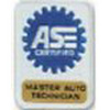
Steps 1-3
pic 1
Steps 4-6
pic 2
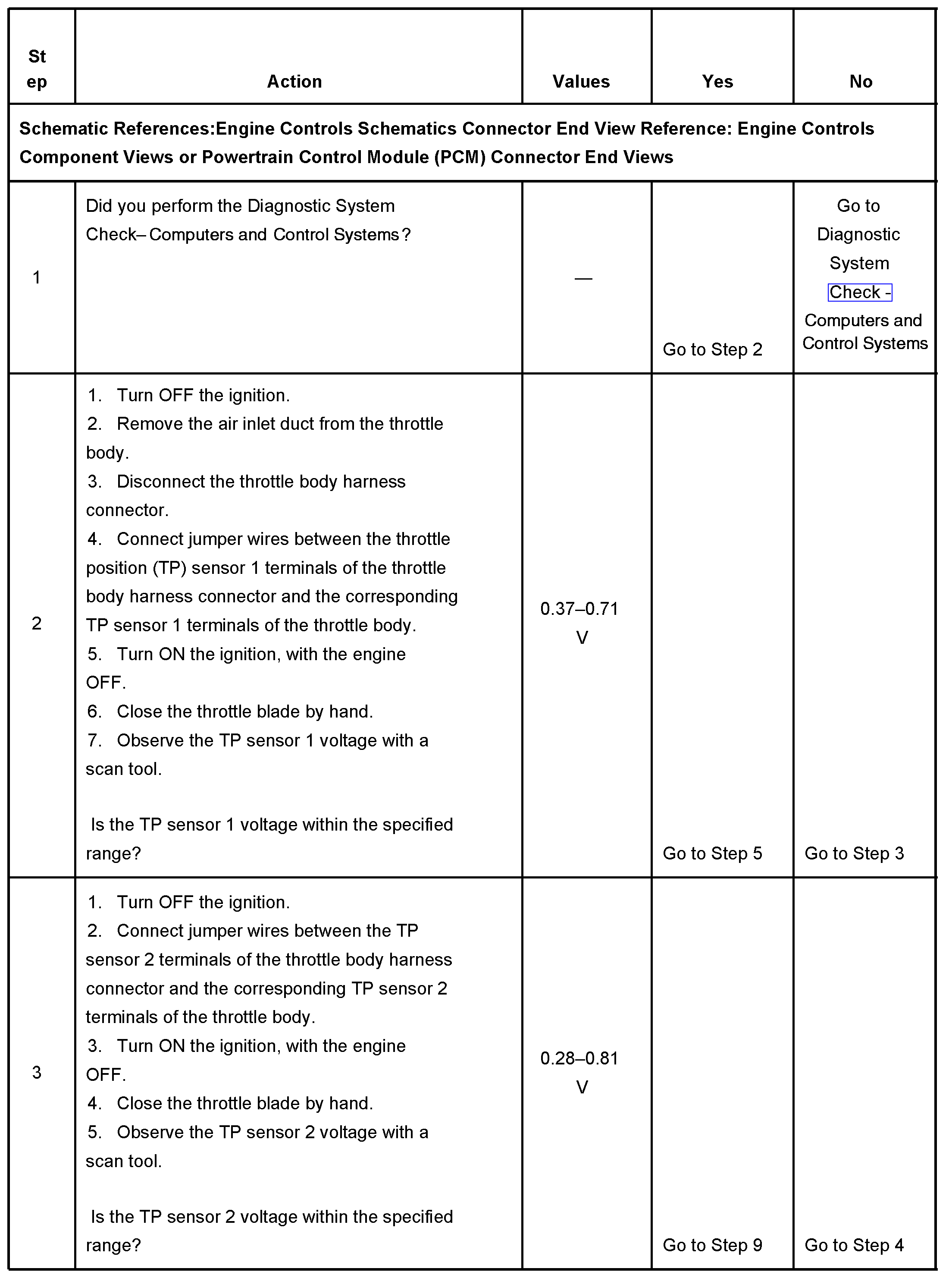
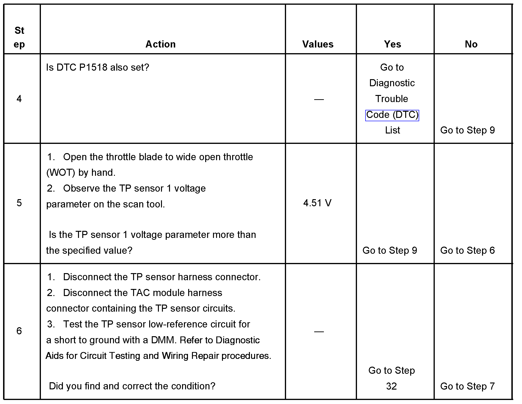
Steps 7-9
pic 3
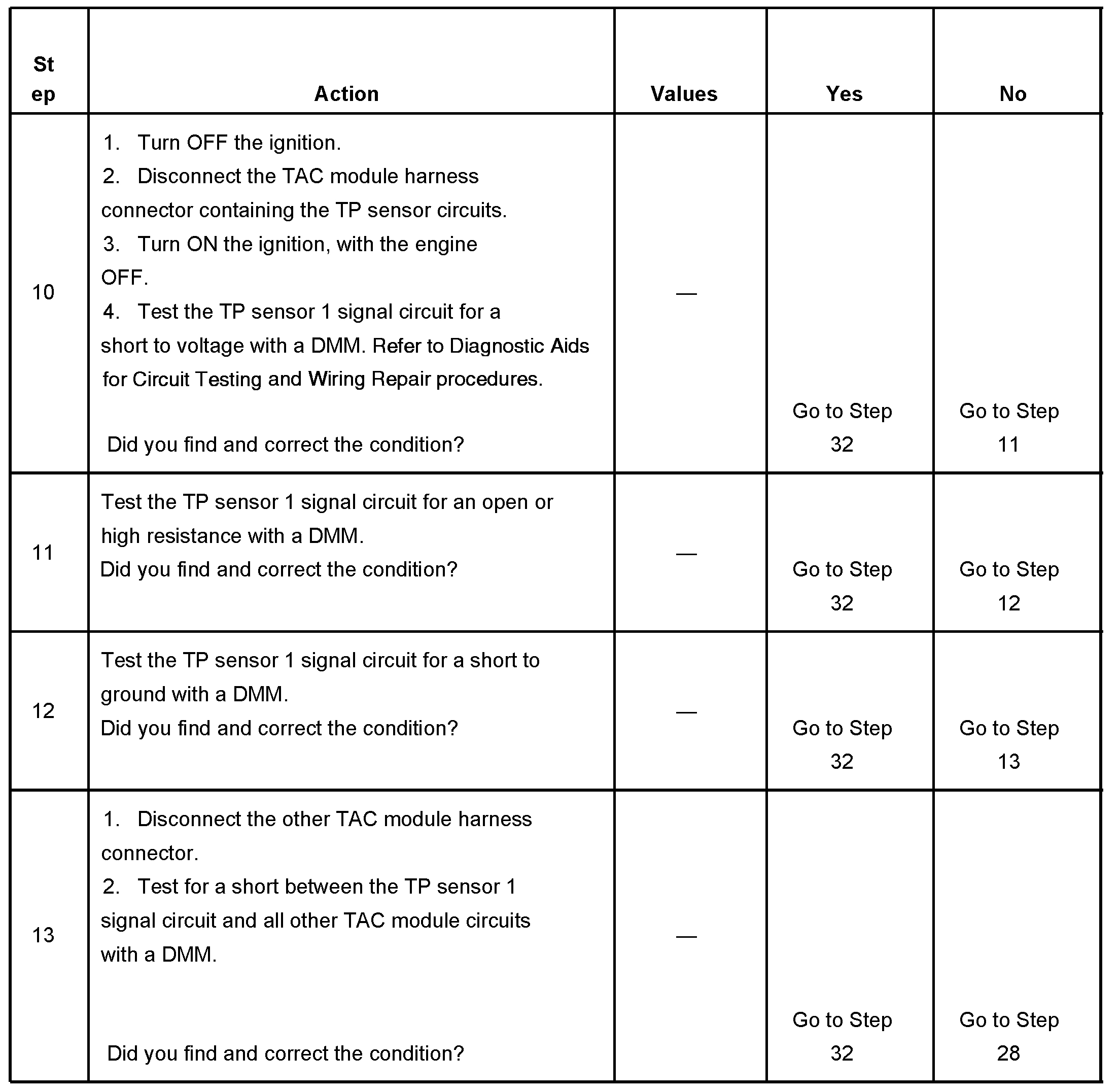
Steps 10-13
pic 4
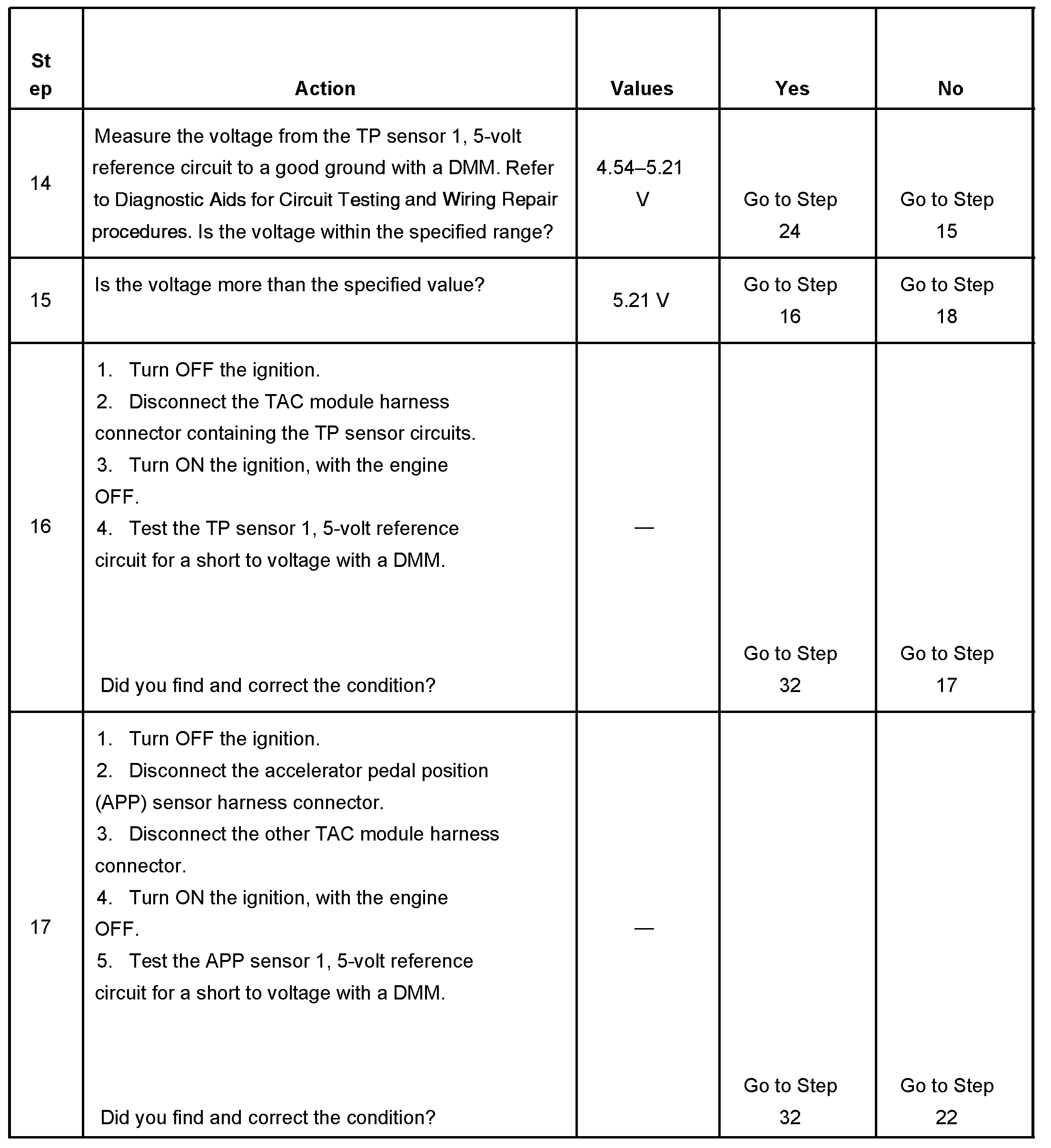
Steps 14-17
pic 5
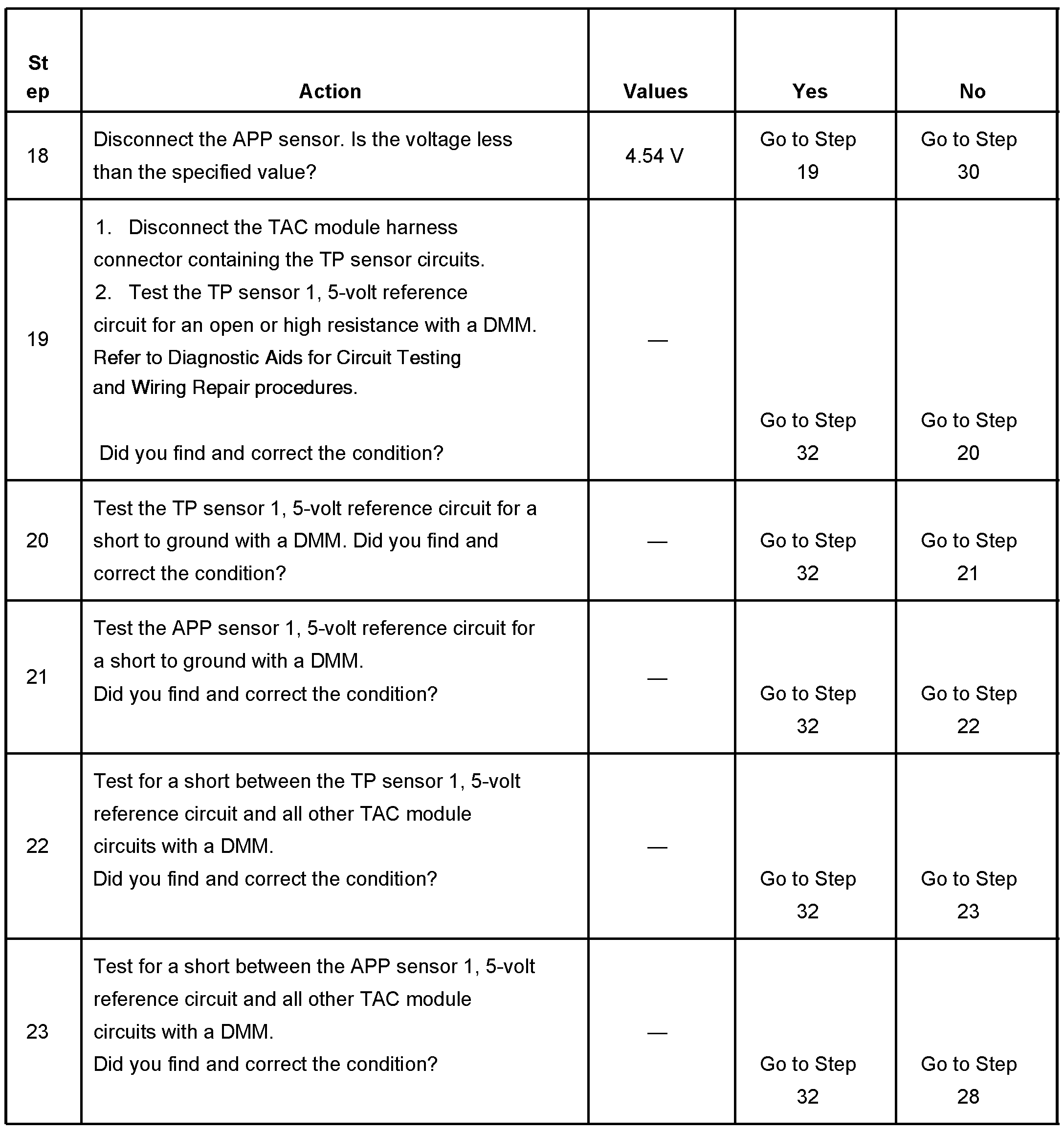
Steps 18-23
pic 6
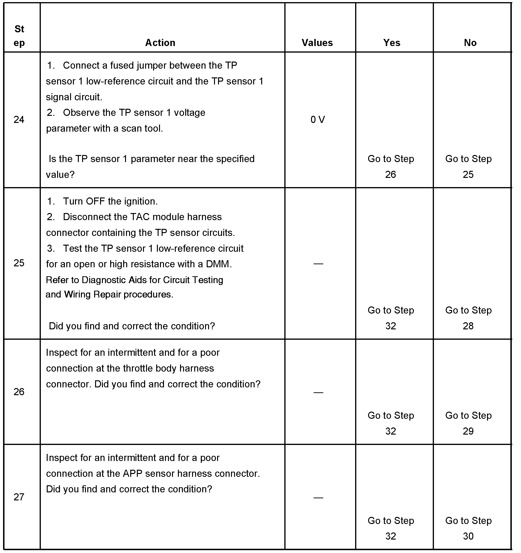
Steps 24-27
pic 7
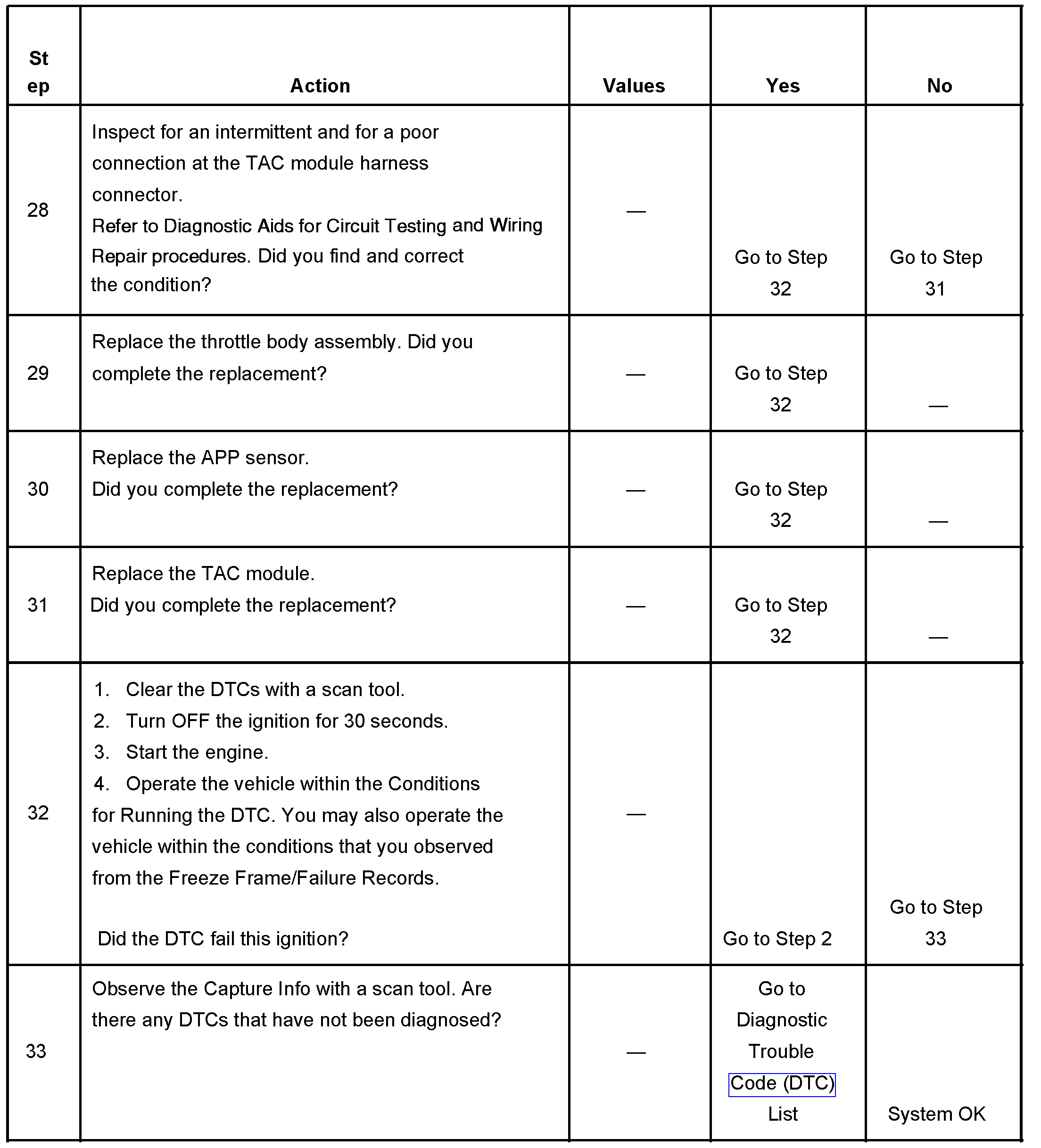
Steps 28-33
pic 8
The number below refers to the step number on the diagnostic table.
33. When the TAC module detects a condition within the TAC system, more than one TAC system related DTC may set. This is due to the many redundant tests run continuously on this system. Locating and repairing one individual condition may correct more than one DTC. Disconnecting components during testing may set additional DTCs. Keep this in mind when reviewing the stored information, Capture Info.
_______________________________________________-
Here are the directions for diagnostics related to the TAC (P01518)
2003 GMC Truck K 1500 Yukon 4WD V8-5.3L VIN T
P1518
Vehicle ALL Diagnostic Trouble Codes ( DTC ) Testing and Inspection P Code Charts P1518
P1518
CIRCUIT DESCRIPTION
The throttle actuator control (TAC) module and the powertrain control module (PCM) communicate via a dedicated serial data circuit. This serial data circuit is separate from any other serial data circuit on the vehicle. Accurate transmitting and receiving of serial data requires not only good circuit integrity but also adequate system voltage. This diagnostic test monitors the accuracy of the serial data transmitted between the TAC module and the PCM. If the PCM detects a loss of data or invalid data, this DTC sets.
CONDITIONS FOR RUNNING THE DTC
- The ignition switch is in the crank or run position.
- The ignition voltage is more than 5.23 volts.
CONDITIONS FOR SETTING THE DTC
- Invalid or missing serial data messages are detected for a predetermined amount of time.
- The above condition is met for more than 1 second.
ACTION TAKEN WHEN THE DTC SETS
- The control module illuminates the malfunction indicator lamp (MIL) when the diagnostic runs and fails.
- The control module records the operating conditions at the time the diagnostic fails. The control module stores this information in the Freeze Frame and/or the Failure Records.
- The control module commands the TAC system to operate in the Reduced Engine Power mode.
OR
- Under certain conditions the control module commands the engine OFF.
- The message center displays Reduced Engine Power.
CONDITIONS FOR CLEARING THE MIL/DTC
- The control module turns OFF the malfunction indicator lamp (MIL) after 3 consecutive ignition cycles that the diagnostic runs and does not fail.
- A current DTC, Last Test Failed, clears when the diagnostic runs and passes.
- A history DTC clears after 40 consecutive warm-up cycles, if no failures are reported by this or any other emission related diagnostic.
- Clear the MIL and the DTC with a scan tool.
DIAGNOSTIC AIDS
- DTC P1518 sets if the battery voltage is low. If the customer's concern is slow cranking or no crank because battery voltage is low, ignore DTC P1518. Clear any DTCs from memory that may have set from the low battery voltage condition.
- DTC P1518 sets when there is a short to B+ on the TAC module ground circuit. Inspect the fuses for the circuits that are in the TAC module harness-i.e. cruise, brake. An inspection of the fuses may lead you to the circuit that is shorted to the TAC module ground circuit.
- DTC P1518 sets if the TAC module ignition feed circuit is shorted to a B+ supply circuit. The TAC module stays powered-up when the ignition switch is turned OFF. When the ignition switch is turned ON, the TAC module is powered-up before the PCM. DTC P1518 sets because no communication is detected by the TAC module from the PCM. Inspect related circuits for being shorted to a B+ supply circuit.
- Inspect the TAC module power and ground circuits and the TAC module/PCM serial data circuits for intermittent connections.
- Inspect the TAC module connectors for signs of water intrusion. If water intrusion occurs, multiple DTCs may set without any circuit or component conditions found during diagnostic testing.
- When the TAC module detects a problem within the TAC system, more than 1 TAC system related DTC may set. This is due to the many redundant tests run continuously on this system. Locating and repairing an individual condition may correct more than 1 DTC. Remember this if you review the stored information in Capture Info.
- For an intermittent condition, refer to Intermittent Conditions. See: Computers and Control Systems > Initial Inspection and Diagnostic Overview > Intermittent Conditions
TEST DESCRIPTION
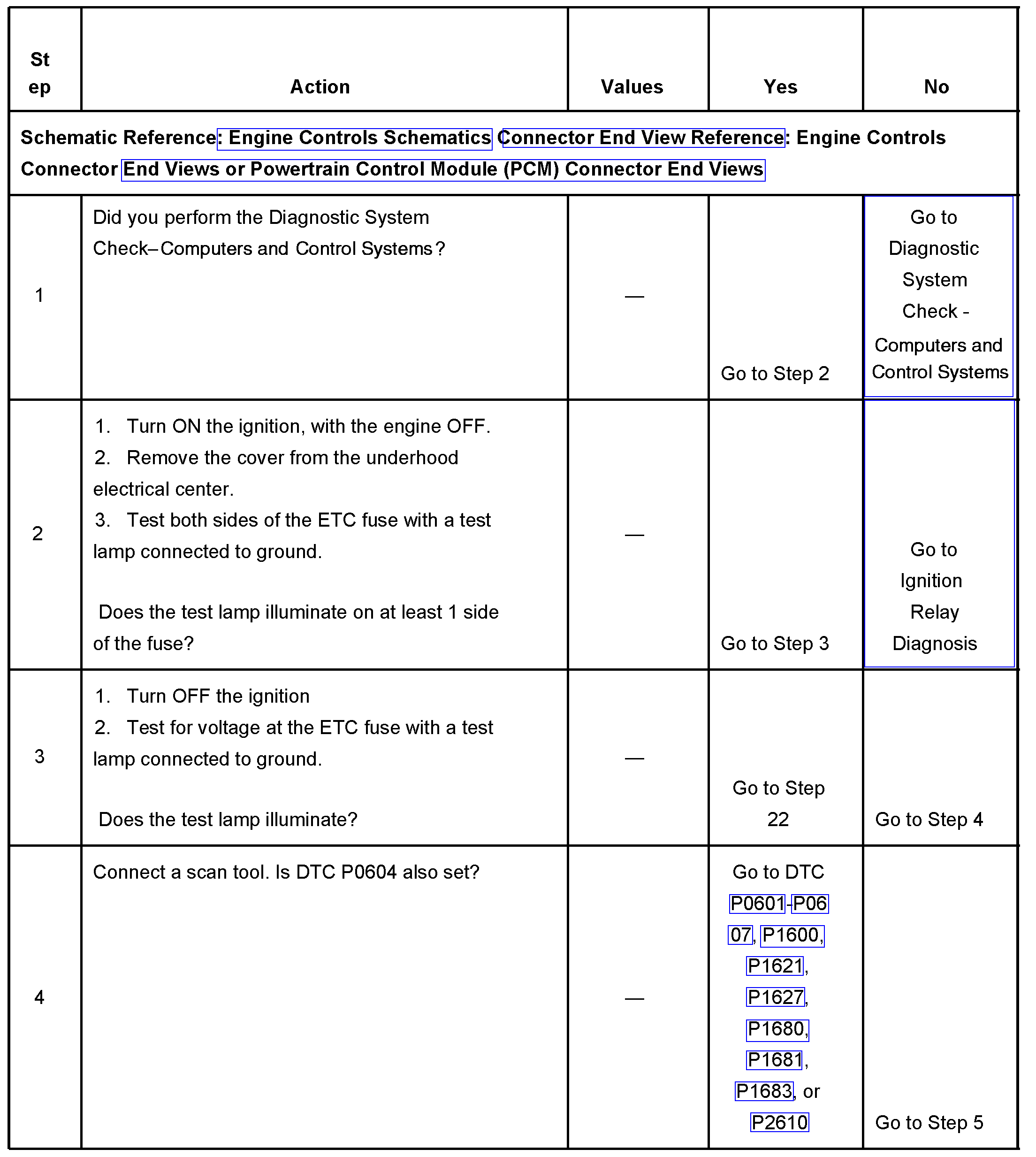
Steps 1-4
pic 9
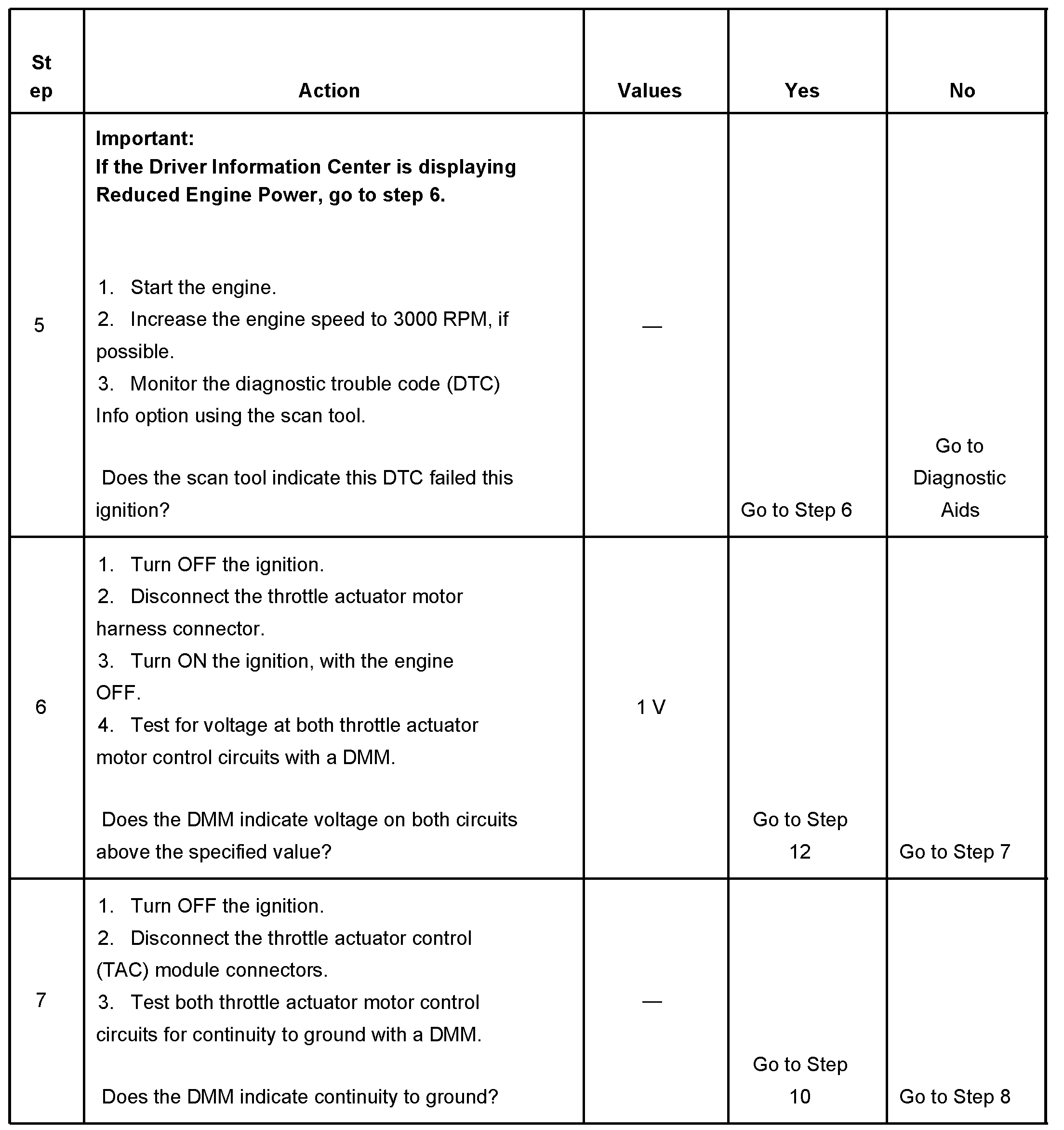
Steps 5-7
pic 10
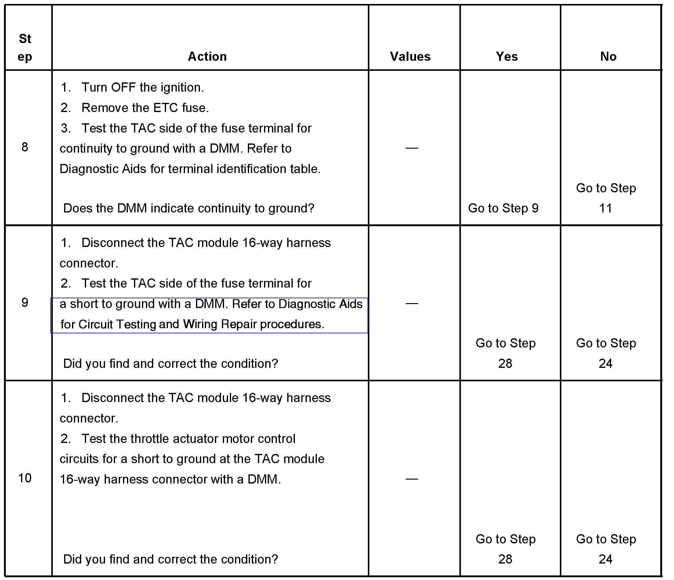
Steps 8-10
pic 11
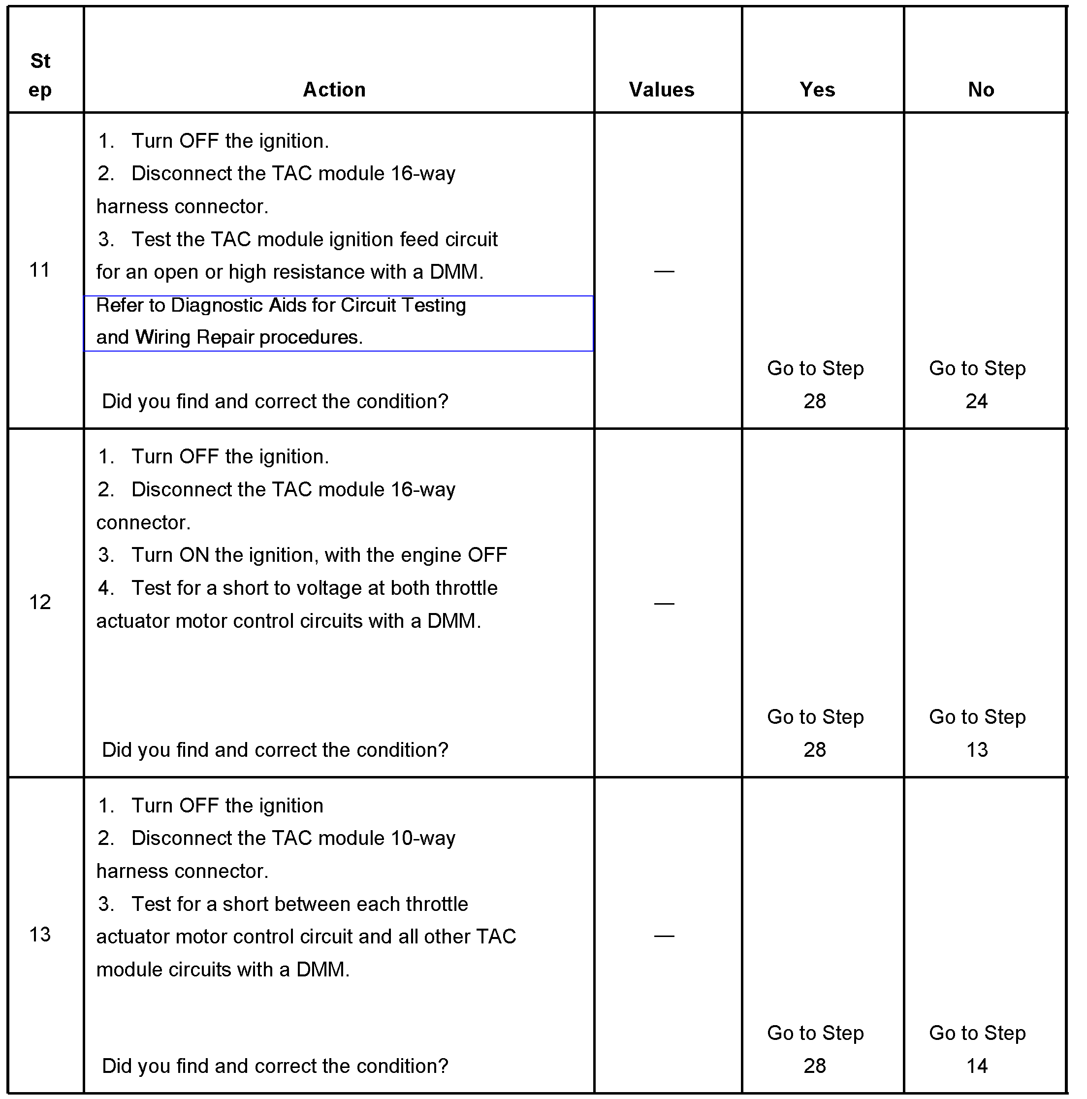
Steps 11-13
pic 12
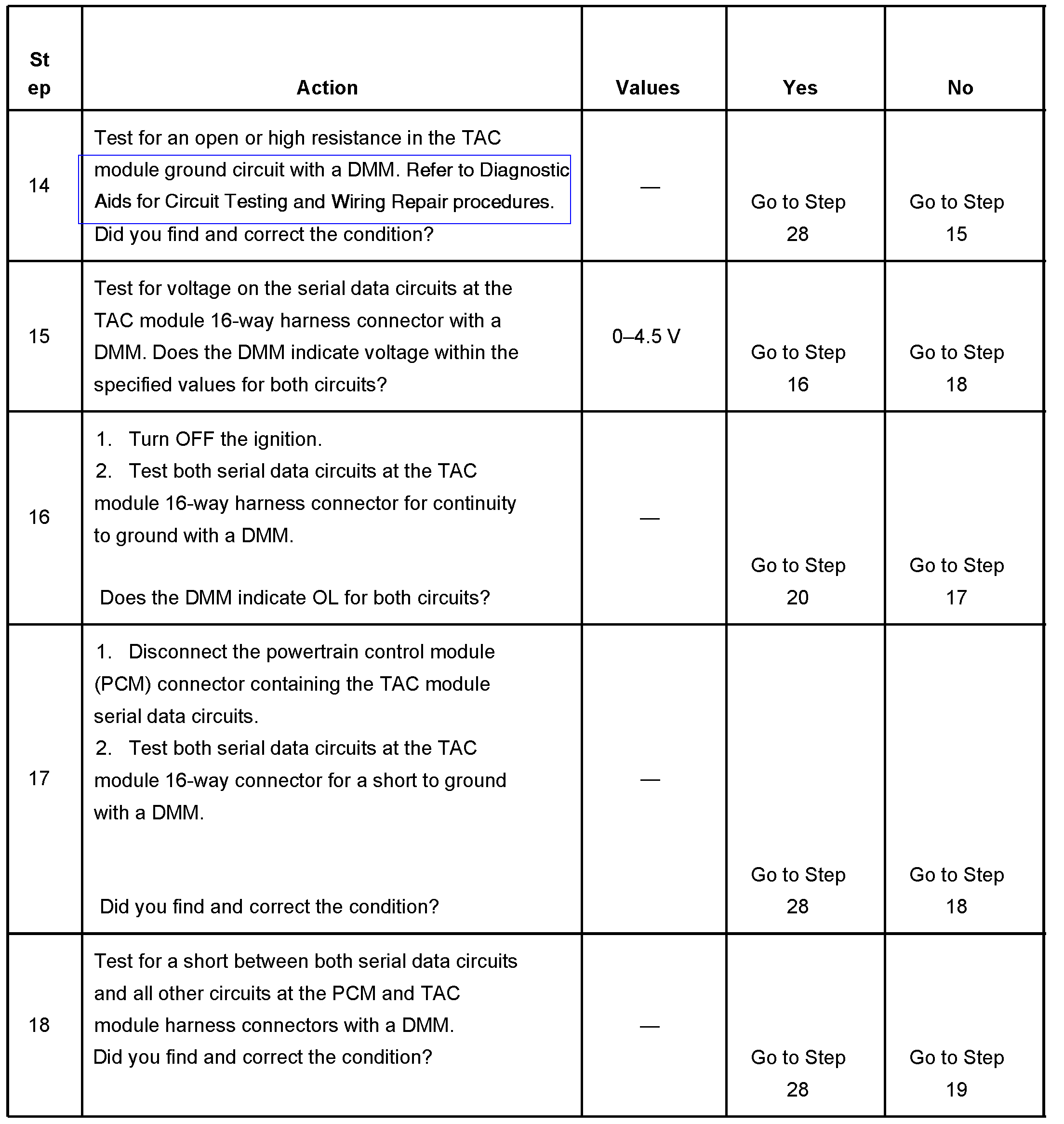
Steps 14-18
pic 13
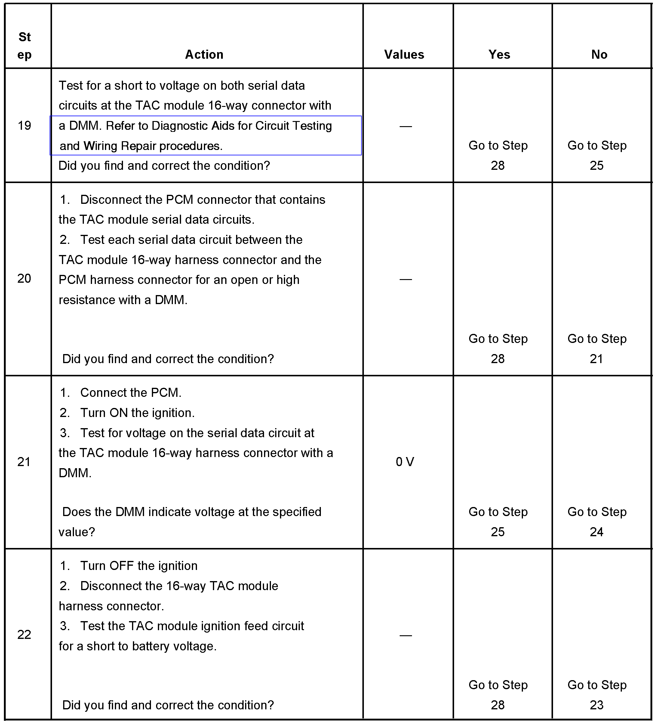
Steps 19-22
pic 14
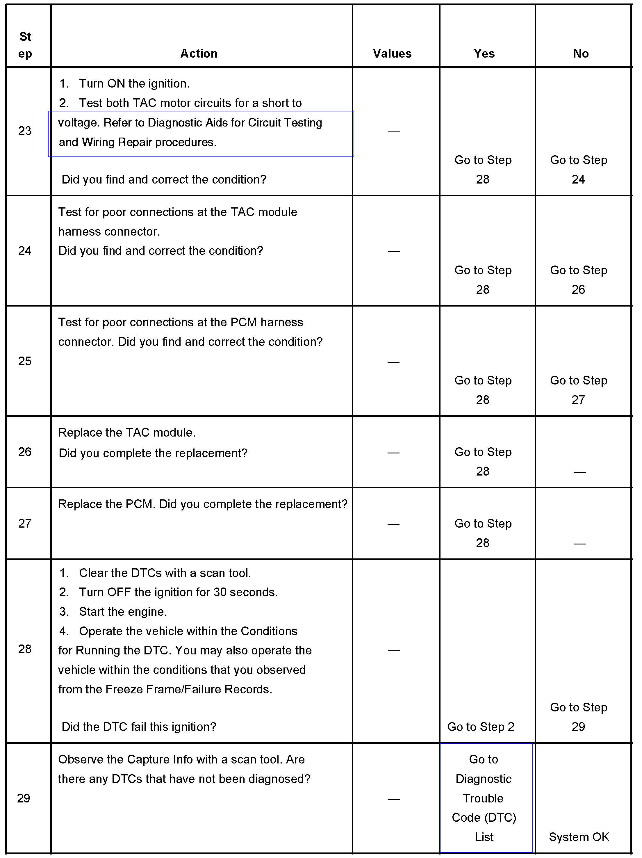
Steps 23-29
pic 15
The numbers below refer to the step numbers on the diagnostic table.
2. This step determines if the ignition relay is supplying a voltage to the ETC fuse.
5. Increasing the engine speed to 3,000 RPM aids in locating a shorted throttle actuator motor control circuit. Depending on the polarity of the throttle actuator motor transistors, this DTC may not set with a fault in the control circuits. The throttle actuator motor is a bi-directional DC motor. Raising the engine speed changes the polarity of the transistors in the throttle actuator motor. This occurs because 1 set of the transistors are low, 0 volts, and the other set are high, B+. Therefore, if 1 set of transistors are at a low voltage and the corresponding circuit is shorted low, DTC P1518 will not set. When the polarity of the transistors change, this DTC sets. If this DTC does not fail this ignition, continue to monitor this DTC status while moving related harnesses and connectors.
29. Locating and repairing an individual condition may correct more than 1 DTC.
__________________________________________
Here are a few links you may find helpful:
https://www.2carpros.com/articles/how-to-use-a-test-light-circuit-tester
https://www.2carpros.com/articles/how-to-use-a-voltmeter
https://www.2carpros.com/articles/how-to-check-wiring
_________________________________________
Let me know if this helps or if you have other questions.
Take care,
Joe
Images (Click to make bigger)
Friday, April 17th, 2020 AT 6:39 PM