Heater blowing hot air on the drivers side?

Tiny
CANADACANDLE
  • MEMBER
  • 2001 PONTIAC GRAND PRIX
  • 6 CYL
  • FWD
  • AUTOMATIC
  • 182,639 MILES
Hello,
I have a 2001 grand prix GT 3.8 L V6 I have been having troubles with the heater blowing hot air on the drivers side. I have the basic dual control system for the climate control. Sometimes it switches from hot to cold air while trying to run with hot air. Sometimes it switches on its own, sometimes I need to adjust the temperature slider to get it to switch over. All the speeds work fine, passenger side works fine, and everything seems to work fine with the air conditioner going. It is the same with all settings for where the air comes out(defrost, all out bottom vents etc.) I have read places that it could be something behind the radio or something on the side near the drivers side door. I just wanted to get a bit of advice on what it could be before I just randomly starting changing parts and ripping my car apart.
Any help would be appreciated.
Brian
Thursday, November 25th, 2010 AT 7:54 PM

7 Replies

Tiny
DR LOOT
  • MECHANIC
  • 2,311 POSTS
This is because the left side blend door actuator needs to be replaced, here is the location and instructions on how to fix the problem. Check out the images (Below). Please let us know what happens.
Was this
answer
helpful?
Yes
No
+1
Friday, November 26th, 2010 AT 6:33 AM
Tiny
CANADACANDLE
  • MEMBER
  • 8 POSTS
WOW!
I don't know if I could even come close to figuring all that out. I have attached a picture of my head unit, I do not think that it gives out codes. I was thinking I could just check out the blend door actuator. I have never done any work with measuring voltage or using a multimeter. Is there a more simplistic way I could go about this?
Was this
answer
helpful?
Yes
No
-1
Friday, November 26th, 2010 AT 1:36 PM
Tiny
DR LOOT
  • MECHANIC
  • 2,311 POSTS
Sorry here is for the Manual system

AIR DELIVERY IMPROPER
2001 Models
Perform A/C-heater diagnostic system check. See A/C-HEATER SYSTEM DIAGNOSTIC SYSTEM CHECK. Go to next step.
Turn ignition switch to ON position. Place blower motor switch to OFF position. If blower motor is off, go to next step. If blower motor is operating, go to BLOWER MOTOR IS ALWAYS ON.
Place blower motor switch in each speed position. If blower motor operates in ANY speed position, go to next step. If blower motor does not operate in any speed position, go to BLOWER MOTOR INOPERATIVE AT ANY SWITCH POSITION.
If blower motor operates in EACH speed position, go to next step. If blower motor does not operate in each speed position, go to BLOWER MOTOR MALFUNCTIONS.
Start engine. Place blower motor switch in maximum speed position. Place mode switch in MAX position. Observe position of recirculation door. Place mode switch in FLOOR position. If recirculation door moves from recirculation position to outside air position, go to next step. If recirculation door does not move as described, inspect vacuum system for kinked, broken or disconnected hoses. Check wiring harness and connectors for clean and tight connections. Repair or replace as necessary.
Operate A/C-heater system to verify repair. Place mode switch in each position. If air delivery system operates normally, problem is intermittent. Check wiring harness and connectors for clean and tight connections. If air delivery system still malfunctions, check vacuum system for kinked, broken or disconnected hoses. Repair or replace as necessary.
Was this
answer
helpful?
Yes
No
-2
Friday, November 26th, 2010 AT 5:25 PM
Tiny
CANADACANDLE
  • MEMBER
  • 8 POSTS
Blower works fine in each position, for all speeds and all positions.
I have a few additional questions/comments.
Where would I be viewing the recirculation door? My system does not have the ability to change from recirculation to outside air position.
I am not sure how this would affect the drivers side air going from hot to cold at various times.
Thanks
Was this
answer
helpful?
Yes
No
-1
Friday, November 26th, 2010 AT 5:57 PM
Tiny
DR LOOT
  • MECHANIC
  • 2,311 POSTS
RECIRCULATED AIR ALWAYS ON
2000 Models
Check vacuum system for disconnected, damaged or leaking hoses. If problem was found, go to next step. If no problem was found, go to step 3.
Repair or replace vacuum hoses and connections as necessary. For further diagnostic procedures, go to TEMPERATURE ACTUATOR INOPERATIVE.
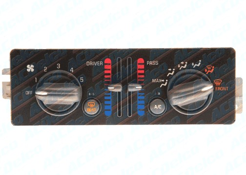
Replace A/C-heater control panel. See A/C-HEATER CONTROL PANEL. After repair, go to next step.
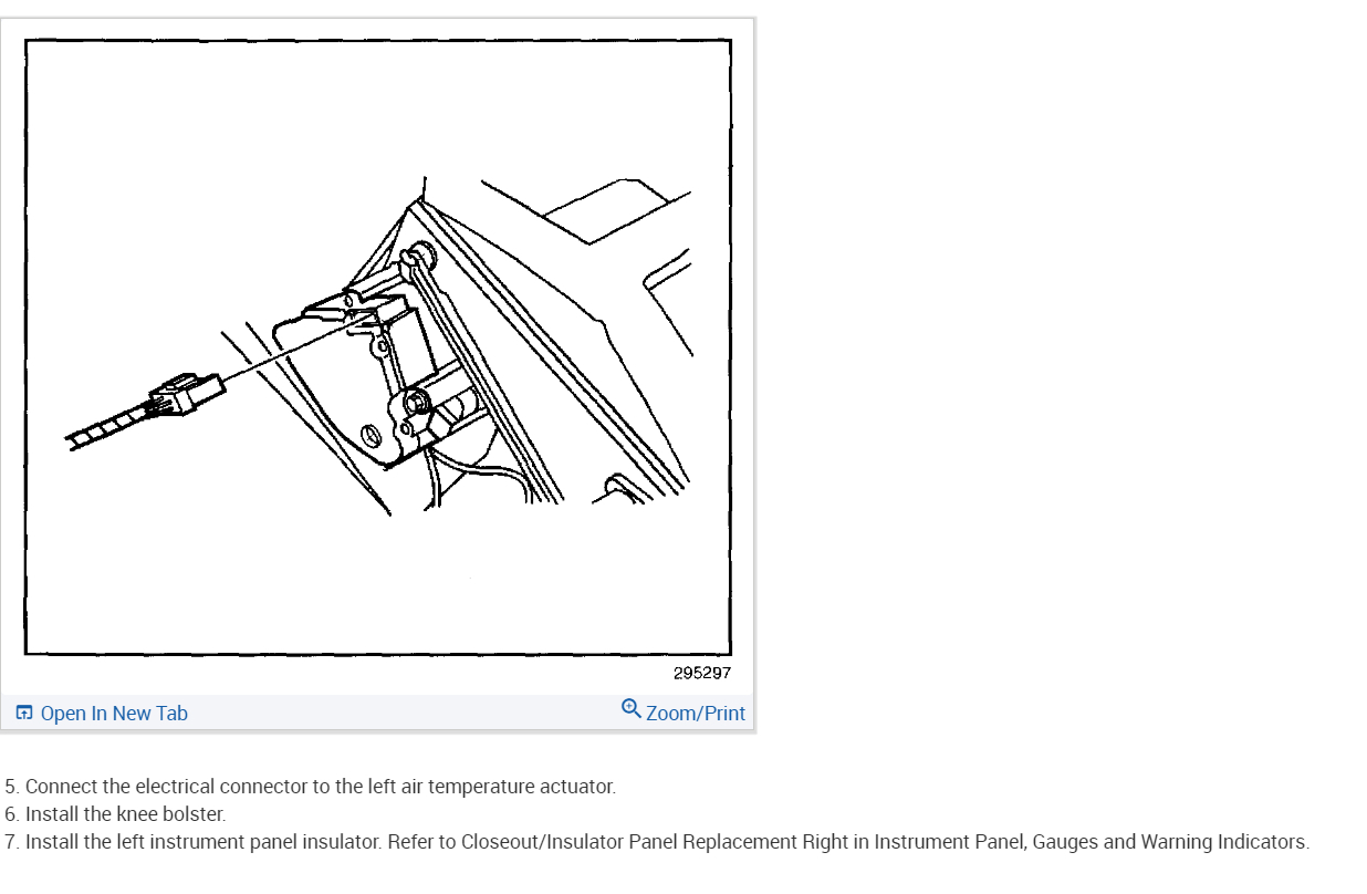
Operate A/C-heater system in all functions to verify repair. If system functions properly, repair is complete. If problem exists, go to appropriate procedure.

TEMPERATURE ACTUATOR INOPERATIVE
2000 Models
Check DIC/HVAC fuse (10-amp) in fuse block. If fuse is faulty, go to next step. If fuse is okay, go to step 3.
Repair short to ground in Brown wire between fuse block and A/C-heater control panel harness connector C2 terminal "C". After repair, go to step 18.
Turn ignition switch to ON position. Using DVOM connected to ground, backprobe A/C-heater control panel harness connector C2 terminal "G" (Light Blue wire). Move temperature control **** from warm to cool and back to warm position. Indicated voltage should vary between 1-12 volts. If voltage varies as described, go to next step. If voltage does not vary as described, go to step 5.
Disconnect left electric actuator harness connector. Using DVOM connected to ground, measure voltage at left electric actuator harness connector terminal No. 10 (Brown wire). If 9-14 volts exists, go to step 6. If 9-14 volts does not exist, go to step 7.
Turn ignition switch to OFF position. Disconnect A/C-heater control panel harness connector C2. Turn ignition switch to ON position. Using DVOM connected to ground, measure voltage at A/C-heater control panel harness connector C2 terminal "C" (Brown wire). If 9-14 volts exists, go to step 16. If 9-14 volts do not exist, go to step 12.
Connect DVOM between left electric actuator harness connector terminals No. 7 (Black wire) and No. 10 (Brown wire). If 9-14 volts exists, go to step 8. If 9-14 volts do not exist, go to step 9.
Repair open or poor connection in Brown wire between left electric actuator harness connector terminal No. 7 and DIC/HVAC fuse (10-amp) located in fuse block. After repair, go to step 18.
Turn ignition switch to ON position. Using DVOM connected to ground, measure voltage at left electric actuator harness connector terminal No. 8 (Light Blue wire). Move temperature control **** from warm to cool and back to warm position. Indicated voltage should vary between 1-12 volts. If voltage varies as described, go to step 10. If voltage does not vary as described, go to step 11.
Locate and repair poor connection or open in Black wire between ground and left electric actuator harness connector terminal No. 7. See WIRING DIAGRAMS. After repair, go to step 18.
Check for poor connection or connector damage at left electric actuator harness connector. Check for faulty linkage or binding of temperature control door. Repair or replace as necessary. If connections and actuator linkage are okay, replace left electric actuator. See LEFT ELECTRIC ACTUATOR under REMOVAL & INSTALLATION. After repair, go to step 18.
Locate and repair poor connection or open in Light Blue wire between A/C-heater control panel harness connector C2 terminal "G" and left electric actuator harness connector terminal No. 8. After repair, go to step 18.
Locate and repair poor connection or open in Brown wire between A/C-heater control panel harness connector C2 terminal "C" and DIC/HVAC fuse (10-amp) located in fuse block. After repair, go to step 18.
Turn ignition switch to OFF position. Disconnect A/C-heater control panel harness connectors. Turn ignition switch to ON position. Using DVOM connected to ground, check Light Blue wire for short to ground between A/C-heater control panel harness connector C2 terminal "G" and left electric actuator harness connector terminal No. 8. If short to ground exists, go to next step. If short to ground does not exist, go to step 15.
Repair short to ground in Light Blue wire between A/C-heater control panel harness connector C2 terminal "G" and left electric actuator harness connector terminal No. 8. After repair, go to step 18.
Replace A/C-heater control panel. See A/C-HEATER CONTROL PANEL under REMOVAL & INSTALLATION. After repair, go to step 18.
Using DVOM, measure voltage between A/C-heater control panel harness connector C2 terminals "C" (Brown wire) and "K" (Black wire). If 9-14 volts does not exist, go to next step. If 9-14 volts exist, go to step 13.
Repair open or poor connection in Black wire between ground and A/C-heater control panel harness connector C2 terminal "K". After repair, go to next step.
Operate A/C-heater system in all functions to verify repair. If temperature actuator functions properly, repair is complete. If temperature actuator is still inoperative, return to step 1.
Was this
answer
helpful?
Yes
No
-1
Friday, November 26th, 2010 AT 6:20 PM
Tiny
DR LOOT
  • MECHANIC
  • 2,311 POSTS
Fig. 2
Was this
answer
helpful?
Yes
No
Friday, November 26th, 2010 AT 6:22 PM
Tiny
CANADACANDLE
  • MEMBER
  • 8 POSTS
The problem is fixed it was the blend door actuator. Thank you.
Was this
answer
helpful?
Yes
No
Friday, November 26th, 2010 AT 7:31 PM

Please login or register to post a reply.

Sponsored links