P0340 = Camshaft Position (CMP) Sensor Maslfunction.
P0446 = EVAP System Ventilation Control Valve Circuit Malfunction.
P0500 = Vehicle Speed Sensor (VSS) Malfunction.
P0102 and P0320 are not listed in the rapair information. Reconfirm they are correct. When codes not listed are present, it could mean a faulty ECM whhci can cause all the codes indicated to be triggerred. If the ECM were to be replaced, ensure there are no shortings in the wiring circuits which had caused the ECM to fail initially.
Don't start replacing components until they have been tested and cnfirmed to be faulty. You mentioned burning smells and with so many codes occurring at the same time, it would most likely be a wiring or control unit problem. Remove the ECM to check for signs of shorting in the circuit board. Perform test to ensure wiring circuits are good. I would suggest starting with the following.
The test are to help you identify if there are any faults with the wiring circuits, pay attention to those resistance test and for shorting to ground.
DTC P0500: VEHICLE SPEED SENSOR (VSS) MALFUNCTION
NOTE:
VSS outputs pulse signal while vehicle is driven.
Trouble Shooting Guide
ECM will set DTC P0500 and illuminate MIL if VSS output voltage has not changed for 4 seconds when:
� Closed throttle position switch is off.
� Engine speed is 3000 RPM or more.
� Engine load is 70 percent or more.
Possible Failure Causes
� VSS failed.
� Open or short VSS circuit, or loose connector.
� ECM failed.
Test Procedures
1, Turn ignition on. Connect scan tool to data link connector and verify DTC P0500 is set. Drive vehicle and check speedometer operation. If speedometer operates okay, go to next step. If speedometer does not operate okay, repair speedometer cable and/or drive gear as necessary. When repairs are completed, clear DTCs and verify operation.
2. Turn ignition off. Check interface between VSS and transaxle gear. If VSS/transaxle interface is okay, go to next step. If VSS/transaxle interface is not okay, repair as necessary. When repairs are completed, clear DTCs and verify fuel tank pressure sensor operation.
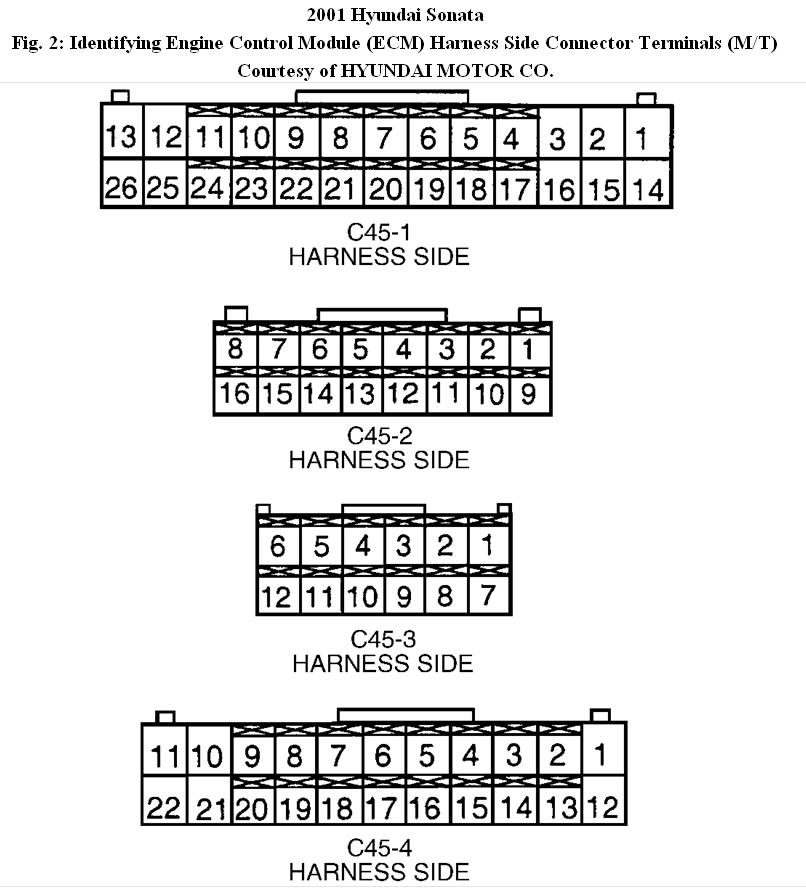
3. Disconnect VSS 3-pin connector. Disconnect ECM connector C44-3 or ECM connector C45-4. Connect jumper wire between ground and VSS connector terminal No. 3 (Brown wire). Measure resistance between ground and ECM connector C44-3 terminal No. 10 (Brown wire) or ECM connector C45-4 terminal No. 16 (Brown wire). If resistance is one
ohm or less, go to next step. If resistance is more than one ohm, repair open in Brown wire between VSS and ECM. When repairs are completed, clear DTCs and verify fuel tank pressure sensor operation.
4. Check for resistance between ground and VSS connector terminal No. 3 (Brown wire). If continuity does not exist, go to next step. If continuity exists, repair short to ground in Brown wire between VSS and ECM. When repairs are completed, clear DTCs and verify fuel tank pressure sensor operation.
5. Verify ECM connector is clean and tight. If connector is okay, replace VSS with known-good sensor. When repairs are completed, clear DTCs and verify operation. If problem persists, replace ECM.
The EVAP system failure could result in difficult refuelling and subsequent restarting, do you have such conditions?
A bad crankshaft sensor fault is known to trigger a cam sensor fault so get it checcked as well.
DTC P0340: CAMSHAFT POSITION (CMP) SENSOR MALFUNCTION
NOTE:
CMP sensor is located at rear of camshaft. CMP sensor detects top dead center of cylinder No. 1 compression stroke. CMP sensor allows ECM to determine fuel injector sequence starting point.
Trouble Shooting Guide
CMP sensor outputs square wave signal when engine is running. ECM will set a DTC P0340 and MIL will be illuminated if CMP sensor output voltage does not change, or normal cylinder identification pattern has not been input, for 4 seconds.
Possible Failure Causes
� CMP sensor failed.
� Open or short in CMP sensor circuit, or loose connector.
� ECM failed.
Test Procedures
1. Turn ignition on. Disconnect CMP sensor 3-pin connector. Measure voltage between ground and CMP sensor connector terminal No. 3 (Pink wire). If battery voltage exists, go to next step. If battery voltage does not exist, repair open in Pink wire between CMP sensor and engine compartment junction block. When repairs are completed, clear DTCs and verify CMP sensor signal is within normal parameters.
2. Turn ignition off. Disconnect ECM connector C44-2 or ECM connector C45-4. Using jumper wire, connect CMP sensor connector terminal No. 2 (Black wire) to ground. Measure resistance between ground and ECM connector C44-2 terminal No. 16 or ECM connector C45-4 terminal No. 18. If resistance is one ohm or less, go to next step. If resistance is more than one ohm, repair open in Black wire between CMP sensor terminal No. 2 and ECM. When repairs are completed, clear DTCs and verify CMP sensor signal is within normal parameters.
3. Check for continuity between ground and CMP sensor connector terminal No. 2 (Black wire). If continuity does not exist, go to next step. If continuity exists, repair short to ground in Black wire between CMP sensor connector terminal No. 2 and ECM. When repairs are completed, clear DTCs and verify CMP sensor signal is within normal parameters.
4. Measure resistance between ground and CMP sensor connector terminal No. 1 (Black wire). If resistance is one ohm or less, go to next step. If resistance is more than one ohm, repair open in wire between CMP sensor connector terminal No. 1 and ground. When repairs are completed, clear DTCs and verify CMP sensor signal is within normal parameters.
5. Inspect CMP sensor for debris or misadjustment. Verify timing is properly adjusted. If problem exists, repair or replace CMP sensor as necessary. If problem does not exist, verify ECM connector is clean and tight. If problem persists, replace ECM. When repairs are completed, clear DTCs and verify CMP sensor signal is within normal parameters.
Image (Click to make bigger)
Monday, January 3rd, 2011 AT 9:14 PM