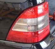
2000 Chevrolet Express flashers and general electrical issues

Tiny
SUPPUSH
  • MEMBER
  • 2000 CHEVROLET EXPRESS
  • 5.0L
  • V8
  • RWD
  • AUTOMATIC
  • 108,000 MILES
I just purchased this vehicle and didn't notice the issue initially. The turn signals are flashing fast during the day with the lights set to off. Wasn't a big deal I thought it was a bulb. But when I turn the lights on, both of my front blinkers flash at the same time, the back ones only flash the indicated direction. I believe the fast flash is related to the flasher module so I have ordered a new one, but I have no idea why left is turning on right and left, and vice versa I see both arrows on the dash light up and both front blinkers are going, also I'm not sure if I have running headlights, sometimes the headlights are on when I'm in gear, sometimes they are not. This is quite puzzling any insight would be appreciated
Wednesday, May 27th, 2015 AT 5:29 PM

6 Replies

Tiny
CARADIODOC
  • MECHANIC
  • 33,738 POSTS
Lights that operate at the wrong time are almost always the result of a broken ground wire. In this case, current flowing through the left front signal bulb can't get to ground, so it looks for an alternate path. That is through the running light filament in the same bulb, then over to the running light on the other side, then to ground at the right bulb. Since the current is going through three filaments instead of just one, current flow is cut to one third of normal for the front circuit. To the electronic flasher that reduced current looks like a bulb is just burned out, and that's why it flashes too fast. The flasher is doing what it is supposed to do.

You can verify a bad ground by watching the operation of the left front signal bulb after you remove the right front bulb from its socket. Typically that will make the left one turn off completely, but GM has used some rather bizarre lighting circuits over the years. The point is you should see some type of change on the left side after removing the right bulb.
Was this
answer
helpful?
Yes
No
Wednesday, May 27th, 2015 AT 7:50 PM
Tiny
SUPPUSH
  • MEMBER
  • 17 POSTS
Ill try that in the morning. Thanks. Can you think of any reason why it only happens with the headlights on?

--martin
Was this
answer
helpful?
Yes
No
Wednesday, May 27th, 2015 AT 7:55 PM
Tiny
CARADIODOC
  • MECHANIC
  • 33,738 POSTS
Yup. Acting differently with the head lights / running lights turned on is another common clue to a bad ground. I have a better answer on a different computer that I can copy and paste to explain it, but you have to have a basic understanding of electrical theory. For now, imagine three people standing on a garden hose and each one is partially-restricting water flow. With the nozzle opened, those restrictions will limit water flow, (current flow), to one third of normal. Now suppose you tee in another hose from another faucet, and connect it to the first hose right behind the person closest to the nozzle. You'll get full pressure and flow from that second hose, but you can see that water flow from the first hose will go way down. You have full pressure from the first faucet and full pressure from the second hose. The first two people standing on the hose have the same water pressure, (voltage) on both sides from two different sources. With the same pressure at both places, no water will flow.

On your vehicle that means no current will flow through two filaments. I'm sorry if that sounds confusing. I can explain it better with diagrams
Was this
answer
helpful?
Yes
No
+2
Wednesday, May 27th, 2015 AT 9:39 PM
Tiny
SUPPUSH
  • MEMBER
  • 17 POSTS
Makes sense, im off work and back to trying my best to figure this one out where would I start looking for a bad ground? Engine, battery, molex on the light control?

Thanks again for the help

--martin
Was this
answer
helpful?
Yes
No
Thursday, May 28th, 2015 AT 3:18 PM
Tiny
CARADIODOC
  • MECHANIC
  • 33,738 POSTS
The ground wires are generally bolted to the body sheet metal near that corner of the vehicle. Typically all the lights in that corner have their ground wires tied together and crimped into a single terminal that is bolted to the body. Normally I would say to follow the wires through the harness, but you're going to find they're all taped up with lots of other wires. Instead, you'll have to push stuff out of the way and look for an uninsulated terminal bolted to the body. Typical places are on the core support alongside the radiator, and on the inner fender, either near the top where the hood closes or lower under the air filter box, battery tray, or something like that.

The problem is though bolts and terminals don't just fall out. More likely you're going to find a wire that has a cut in the insulation and the wire corroded, or something hooked it and tore it. The wires could be corroded in the crimp on that terminal too. Often, if the circuit is turned on, you'll see a telltale spark when you disturb the broken connection.

If you want to test something to verify I'm as smart as I have you fooled into thinking I am, you can do that with a digital volt / ohm meter. Do you have one and know how to use it? I'm pretty sure you're going to have a 3157 bulb for the turn signal / running light. That has a flat plastic base with four wires wrapped around it. I don't know if this will reproduce correctly, but in that socket with the bulb removed, the four terminals will look like:
_____ _____
_____ _____

Two of them. Lets say the two on the left, will be tied together. Those are the ground connections, one for each filament in the bulb. One on the right is the 12 volt feed for the running light and the other right one is the 12 volt feed for the turn signal. Turn on the running / tail lights, then test for voltage on these four terminals. You should have 12 volts on just one of them. The other three are supposed to have 0 volts, but in this case I think you're going to find something in the order of four to six volts feeding from the other side. I could be wrong on that, so don't get wrapped around the axle if you find 0 volts.

The point is, in my sad story lets say you find 12 volts on one of the right terminals. That means the two on the left are supposed to go to ground, and you can test that with the ohm meter. Switch it to the lowest ohms scale, put one meter probe on the battery's negative post, or a paint-free point on the body or a bolt head, and the other probe on those two terminals on the left. You're supposed to find 0.0 ohms but due to the normal resistance in the wires and in the meter leads, two to maybe six ohms is typical. If we're on the right track, you're going to find an "over-range" indication meaning there's an open circuit and the infinite resistance is more than the meter will measure on that scale. Now it's just a matter of following those ground wires to the break.
Was this
answer
helpful?
Yes
No
Thursday, May 28th, 2015 AT 8:47 PM
Tiny
SUPPUSH
  • MEMBER
  • 17 POSTS
Awesome thanks that's going to be tomorrows project I got caught up replacing the water pump tonight

thanks again

--martin
Was this
answer
helpful?
Yes
No
Thursday, May 28th, 2015 AT 9:16 PM

Please login or register to post a reply.

Sponsored links